US5007268A - Method and device for edge-finishing - Google Patents
Method and device for edge-finishing Download PDFInfo
- Publication number
- US5007268A US5007268A US07/477,186 US47718690A US5007268A US 5007268 A US5007268 A US 5007268A US 47718690 A US47718690 A US 47718690A US 5007268 A US5007268 A US 5007268A
- Authority
- US
- United States
- Prior art keywords
- edge
- tip
- workpiece
- notch
- flank
- Prior art date
- Legal status (The legal status is an assumption and is not a legal conclusion. Google has not performed a legal analysis and makes no representation as to the accuracy of the status listed.)
- Expired - Fee Related
Links
- 238000000034 method Methods 0.000 title claims description 6
- 238000010009 beating Methods 0.000 claims description 4
- 230000003116 impacting effect Effects 0.000 claims description 2
- 238000005452 bending Methods 0.000 description 1
- 230000003628 erosive effect Effects 0.000 description 1
- 238000009499 grossing Methods 0.000 description 1
- 238000007790 scraping Methods 0.000 description 1
- 239000000126 substance Substances 0.000 description 1
Images


Classifications
-
- B—PERFORMING OPERATIONS; TRANSPORTING
- B21—MECHANICAL METAL-WORKING WITHOUT ESSENTIALLY REMOVING MATERIAL; PUNCHING METAL
- B21D—WORKING OR PROCESSING OF SHEET METAL OR METAL TUBES, RODS OR PROFILES WITHOUT ESSENTIALLY REMOVING MATERIAL; PUNCHING METAL
- B21D19/00—Flanging or other edge treatment, e.g. of tubes
- B21D19/005—Edge deburring or smoothing
-
- Y—GENERAL TAGGING OF NEW TECHNOLOGICAL DEVELOPMENTS; GENERAL TAGGING OF CROSS-SECTIONAL TECHNOLOGIES SPANNING OVER SEVERAL SECTIONS OF THE IPC; TECHNICAL SUBJECTS COVERED BY FORMER USPC CROSS-REFERENCE ART COLLECTIONS [XRACs] AND DIGESTS
- Y10—TECHNICAL SUBJECTS COVERED BY FORMER USPC
- Y10S—TECHNICAL SUBJECTS COVERED BY FORMER USPC CROSS-REFERENCE ART COLLECTIONS [XRACs] AND DIGESTS
- Y10S72/00—Metal deforming
- Y10S72/71—Vibrating
-
- Y—GENERAL TAGGING OF NEW TECHNOLOGICAL DEVELOPMENTS; GENERAL TAGGING OF CROSS-SECTIONAL TECHNOLOGIES SPANNING OVER SEVERAL SECTIONS OF THE IPC; TECHNICAL SUBJECTS COVERED BY FORMER USPC CROSS-REFERENCE ART COLLECTIONS [XRACs] AND DIGESTS
- Y10—TECHNICAL SUBJECTS COVERED BY FORMER USPC
- Y10T—TECHNICAL SUBJECTS COVERED BY FORMER US CLASSIFICATION
- Y10T29/00—Metal working
- Y10T29/45—Scale remover or preventor
- Y10T29/4572—Mechanically powered operator
- Y10T29/4583—Hammer
-
- Y—GENERAL TAGGING OF NEW TECHNOLOGICAL DEVELOPMENTS; GENERAL TAGGING OF CROSS-SECTIONAL TECHNOLOGIES SPANNING OVER SEVERAL SECTIONS OF THE IPC; TECHNICAL SUBJECTS COVERED BY FORMER USPC CROSS-REFERENCE ART COLLECTIONS [XRACs] AND DIGESTS
- Y10—TECHNICAL SUBJECTS COVERED BY FORMER USPC
- Y10T—TECHNICAL SUBJECTS COVERED BY FORMER US CLASSIFICATION
- Y10T29/00—Metal working
- Y10T29/45—Scale remover or preventor
- Y10T29/4572—Mechanically powered operator
- Y10T29/4589—Blade or chisel
-
- Y—GENERAL TAGGING OF NEW TECHNOLOGICAL DEVELOPMENTS; GENERAL TAGGING OF CROSS-SECTIONAL TECHNOLOGIES SPANNING OVER SEVERAL SECTIONS OF THE IPC; TECHNICAL SUBJECTS COVERED BY FORMER USPC CROSS-REFERENCE ART COLLECTIONS [XRACs] AND DIGESTS
- Y10—TECHNICAL SUBJECTS COVERED BY FORMER USPC
- Y10T—TECHNICAL SUBJECTS COVERED BY FORMER US CLASSIFICATION
- Y10T29/00—Metal working
- Y10T29/45—Scale remover or preventor
- Y10T29/4594—Hand tool
-
- Y—GENERAL TAGGING OF NEW TECHNOLOGICAL DEVELOPMENTS; GENERAL TAGGING OF CROSS-SECTIONAL TECHNOLOGIES SPANNING OVER SEVERAL SECTIONS OF THE IPC; TECHNICAL SUBJECTS COVERED BY FORMER USPC CROSS-REFERENCE ART COLLECTIONS [XRACs] AND DIGESTS
- Y10—TECHNICAL SUBJECTS COVERED BY FORMER USPC
- Y10T—TECHNICAL SUBJECTS COVERED BY FORMER US CLASSIFICATION
- Y10T29/00—Metal working
- Y10T29/47—Burnishing
- Y10T29/471—Burnishing of water laid fibrous article [e.g., paper]
- Y10T29/473—Heated burnishing member
- Y10T29/474—Burnishing tool reciprocates across work surface
Definitions
- the present invention relates to the finishing-off of edges on workpieces by the smoothing of existing edges by the removal of burrs, sharp edges, fettles or other protrusions through peening and/or breaking away of the unwanted material on the edge prior to forming a clean smooth edge.
- Edge finishing and deburring are operations that must be carried out on many objects after they have been machined, cut or otherwise formed. At present these operations are carried out by hand (by filing or scraping), by grinding, by chemical erosion methods or by some other means. None of these methods is considered to be totally satisfactory.
- the present invention further provides a method of finishing a workpiece edge, comprising reciprocating against the edge a tip of an edge-finishing device, the tip having a notch, the base of the notch having a curved surface which determines the edge finish and the notch having flank faces for guiding the tip onto the workpiece edge, the tip beating a burr or protrusion on the workpiece edge thin enough that it is broken or driven off the edge, the flank faces preferably each comprising an outer flank surface for guiding the tip onto the workpiece edge and an inner flank surface, at least one of the inner flank surfaces beating the burr or protrusion.
- FIG. 1a shows a side view of a tip
- FIG. 1b shows a sectional view of the tip of FIG. 1a
- FIG. 1c shows the upper end of the tip of FIG. 1a in plan view
- FIG. 1d shows a perspective view of the tip of FIG. 1a.
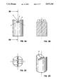
- FIG. 2a shows another tip
- FIG. 2b shows a sectional view of the tip of FIG. 2a
- FIG. 2c shows the upper end of the tip of FIG. 2a in plan view
- FIG. 2d shows perspective view of the tip of FIG. 2a.
- FIG. 3a to 3c each show a different configuration of the base of the notch.
- FIG. 4 shows one of the tips fitted in a holder.
- FIG. 5a illustrates operation of the device
- FIG. 5b shows a finished edge
- a tip with a notch formed into its end In one example of the invention there is provided a tip with a notch formed into its end. The notched end of the tip is impacted against a workpiece edge as shown in FIG. 5a.
- the reciprocating action is provided by a prime mover, usually an electrically or pneumatically powered drive.
- FIG. 4 A typical embodiment of the invention is shown in FIG. 4, whereby a tip N is held in a holder M and a reciprocating drive unit L provides the impacting action.
- FIG. 1a to 1d show a tip having a root curve C at the base of a notch A formed by flank surfaces D.
- FIGS. 2a to 2d show a tip N with a notch H formed by flank surfaces each having an outer flank surface K.
- a root curve J curves into inner flank surfaces I which lead in turn into the outer flank surfaces K.
- the tip combines a number of important variables:
- This provides for a contact area (land) onto the workpiece edge.
- the harder the material to be finished the lesser the contact area or land required, and thus the lesser the land surface radius required.
- the land surface has a radius which would, typically, be 20 mm.
- the outer flank surfaces help to initially guide the tip on the workpiece edge.
- the outer flank surfaces K lead into the inner flank surfaces I, which bend or beat the protrusion or burr over the side of the workpiece until it is broken off.
- the inner flank surfaces have a radius which would, typically, be 1 mm.
- the root curve J has a radius which would, typically, be 0.25 mm.
- FIGS. 1a to 1d show an example of a tip.
- This tip has a root curve C at the base of the notch A formed by the flank surfaces D.
- the flank surfaces are flat and the land B is a straight trough forming the contact area before tapering away outwards clearing the workpiece.
- FIGS. 2a and 2d show a tip with a notch H formed by the outer flank surfaces K.
- the root curve J merges into the inner flank surfaces I which lead in turn into the outer flank surfaces K.
- FIGS. 3a, 3b and 3c show three possible land configurations.
- FIG. 3a depicts a tip E with a flat land X of infinite radius.
- FIG. 3b is a tip E with a land of constant radius Y.
- FIG. 3c shows a tip G with a land of changing radii Z.
- FIG. 4 shows how a tip N is configured with a holder M and a drive unit L.
- the tip is offered against the workpiece edge using the outer flank surfaces of the notch for guidance.
- FIG. 5a illustrates the principle of operation.
- the tip W impacts against the edge of the workpiece P, bending over any protrusion S encountered.
- the direction of motion is indicated by the double arrow Q and the stroke length is represented by R.
- the tip continues to impact until the inner flank surfaces beat the protrusion sufficiently thin that it breaks, tears or is driven off.
- the tip still continues to impact against the edge until the finish T conforms to the finish provided for by the root curve.
- the device is traversed along the edge of the workpiece until the desired finish is obtained. This is done by hand or by machine. Alternatively the device is fixed in position and the workpiece moved across the tip.
Landscapes
- Engineering & Computer Science (AREA)
- Mechanical Engineering (AREA)
- Finish Polishing, Edge Sharpening, And Grinding By Specific Grinding Devices (AREA)
- Electrical Discharge Machining, Electrochemical Machining, And Combined Machining (AREA)
- Cutting Tools, Boring Holders, And Turrets (AREA)
- Bending Of Plates, Rods, And Pipes (AREA)
- Grinding And Polishing Of Tertiary Curved Surfaces And Surfaces With Complex Shapes (AREA)
- Turning (AREA)
Abstract
Description
Claims (4)
Applications Claiming Priority (4)
| Application Number | Priority Date | Filing Date | Title |
|---|---|---|---|
| GB8531222 | 1985-12-19 | ||
| GB858531222A GB8531222D0 (en) | 1985-12-19 | 1985-12-19 | Burr removing device |
| GB868618523A GB8618523D0 (en) | 1985-12-19 | 1986-07-30 | Edge finishing device |
| GB8618523 | 1986-07-30 |
Related Parent Applications (1)
| Application Number | Title | Priority Date | Filing Date |
|---|---|---|---|
| US07356675 Continuation | 1989-05-23 |
Publications (1)
| Publication Number | Publication Date |
|---|---|
| US5007268A true US5007268A (en) | 1991-04-16 |
Family
ID=26290137
Family Applications (1)
| Application Number | Title | Priority Date | Filing Date |
|---|---|---|---|
| US07/477,186 Expired - Fee Related US5007268A (en) | 1985-12-19 | 1990-02-05 | Method and device for edge-finishing |
Country Status (7)
| Country | Link |
|---|---|
| US (1) | US5007268A (en) |
| EP (1) | EP0289501B1 (en) |
| AT (1) | ATE78199T1 (en) |
| AU (1) | AU601711B2 (en) |
| DE (1) | DE3686056T2 (en) |
| GB (1) | GB2206827B (en) |
| WO (1) | WO1987003830A1 (en) |
Cited By (2)
| Publication number | Priority date | Publication date | Assignee | Title |
|---|---|---|---|---|
| CN110842095A (en) * | 2019-11-21 | 2020-02-28 | 徐州欧百瑞智能设备有限公司 | Pressing plate for trimming equipment protection skin |
| US20220161373A1 (en) * | 2020-11-24 | 2022-05-26 | SEVENTY EIGHT Co., Ltd. | Scraper for removing a welded material adhering to a work piece |
Citations (5)
| Publication number | Priority date | Publication date | Assignee | Title |
|---|---|---|---|---|
| US3150888A (en) * | 1962-05-08 | 1964-09-29 | Ingersoll Rand Co | Coupling means |
| US3926031A (en) * | 1975-01-23 | 1975-12-16 | Hildaur L Neilsen | Deburring device with oppositely acting deburring elements |
| US3937055A (en) * | 1974-11-06 | 1976-02-10 | The United States Of America As Represented By The United States National Aeronautics And Space Administration | Method of peening and portable peening gun |
| US4605073A (en) * | 1983-07-01 | 1986-08-12 | Nilsson Goran Alfred | Device in needle hammers |
| US4641510A (en) * | 1984-11-17 | 1987-02-10 | Messerschmitt-Boelkow-Blohm Gesellschaft Mit Beschraenkter Haftung | Electromagnetically operated peening tool |
Family Cites Families (3)
| Publication number | Priority date | Publication date | Assignee | Title |
|---|---|---|---|---|
| FR1160456A (en) * | 1956-10-31 | 1958-07-16 | Percussion forging | |
| US3707087A (en) * | 1971-06-16 | 1972-12-26 | Hildaur L Neilsen | Deburring devices |
| US3866452A (en) * | 1974-04-29 | 1975-02-18 | Hildaur L Neilsen | Deburring device |
-
1986
- 1986-12-18 DE DE8787900217T patent/DE3686056T2/en not_active Expired - Fee Related
- 1986-12-18 WO PCT/GB1986/000777 patent/WO1987003830A1/en not_active Ceased
- 1986-12-18 EP EP87900217A patent/EP0289501B1/en not_active Expired - Lifetime
- 1986-12-18 AU AU67785/87A patent/AU601711B2/en not_active Ceased
- 1986-12-18 AT AT87900217T patent/ATE78199T1/en active
- 1986-12-18 GB GB8814499A patent/GB2206827B/en not_active Expired - Lifetime
-
1990
- 1990-02-05 US US07/477,186 patent/US5007268A/en not_active Expired - Fee Related
Patent Citations (5)
| Publication number | Priority date | Publication date | Assignee | Title |
|---|---|---|---|---|
| US3150888A (en) * | 1962-05-08 | 1964-09-29 | Ingersoll Rand Co | Coupling means |
| US3937055A (en) * | 1974-11-06 | 1976-02-10 | The United States Of America As Represented By The United States National Aeronautics And Space Administration | Method of peening and portable peening gun |
| US3926031A (en) * | 1975-01-23 | 1975-12-16 | Hildaur L Neilsen | Deburring device with oppositely acting deburring elements |
| US4605073A (en) * | 1983-07-01 | 1986-08-12 | Nilsson Goran Alfred | Device in needle hammers |
| US4641510A (en) * | 1984-11-17 | 1987-02-10 | Messerschmitt-Boelkow-Blohm Gesellschaft Mit Beschraenkter Haftung | Electromagnetically operated peening tool |
Cited By (2)
| Publication number | Priority date | Publication date | Assignee | Title |
|---|---|---|---|---|
| CN110842095A (en) * | 2019-11-21 | 2020-02-28 | 徐州欧百瑞智能设备有限公司 | Pressing plate for trimming equipment protection skin |
| US20220161373A1 (en) * | 2020-11-24 | 2022-05-26 | SEVENTY EIGHT Co., Ltd. | Scraper for removing a welded material adhering to a work piece |
Also Published As
| Publication number | Publication date |
|---|---|
| EP0289501A1 (en) | 1988-11-09 |
| DE3686056D1 (en) | 1992-08-20 |
| AU601711B2 (en) | 1990-09-20 |
| GB8814499D0 (en) | 1988-07-27 |
| AU6778587A (en) | 1987-07-15 |
| GB2206827A (en) | 1989-01-18 |
| DE3686056T2 (en) | 1993-02-25 |
| EP0289501B1 (en) | 1992-07-15 |
| GB2206827B (en) | 1990-01-10 |
| WO1987003830A1 (en) | 1987-07-02 |
| ATE78199T1 (en) | 1992-08-15 |
Similar Documents
| Publication | Publication Date | Title |
|---|---|---|
| US4625725A (en) | Surgical rasp and method of manufacture | |
| US6872125B2 (en) | Tool for smoothing a workpiece | |
| CA2003735C (en) | Deburring tool with cutting blades | |
| US6220139B1 (en) | Saw blade | |
| US20060212060A1 (en) | Arthroscopic shaver and method of manufacturing same | |
| WO1996005931A1 (en) | Saw blade tooth form and method therefor | |
| US20110183580A1 (en) | Apparatus and method for intricate cuts | |
| WO2006012447A2 (en) | An improved saw cutting blade | |
| RU2061586C1 (en) | Method of blank machining | |
| JP2005119320A (en) | Saw blade | |
| US5901630A (en) | Band saw blade or hacksaw with double formation of cutting elements | |
| US5669744A (en) | Rotary chisel | |
| JPS6159869B2 (en) | ||
| US6796034B2 (en) | Interchangeable head carving tool | |
| US5626446A (en) | Flat drill bit with opposing vertical cutting edges | |
| US5007268A (en) | Method and device for edge-finishing | |
| JP6247679B2 (en) | Band saw blade manufacturing method and band saw blade | |
| WO1999012683A1 (en) | Tool bit with undercut hook radius | |
| EP1382414B1 (en) | Method of making a cutting tool blade | |
| US4027647A (en) | Planing and cutting tool | |
| RU2296652C1 (en) | Needle-milling cutter for processing of planes with pulse loading | |
| EP1179997B1 (en) | Abrasive tool having safe and active areas | |
| WO1992002345A1 (en) | Chisel for dust-free chasing of brick structures | |
| RU2055703C1 (en) | Intermittent needle milling method | |
| RU2131803C1 (en) | Elongate flat product grinding method |
Legal Events
| Date | Code | Title | Description |
|---|---|---|---|
| AS | Assignment |
Owner name: ORIGINATIONS LIMITED, AVONDALE WORKSHOPS, WOODLAND Free format text: ASSIGNMENT OF ASSIGNORS INTEREST.;ASSIGNOR:KELLY, NIGEL B.;REEL/FRAME:005568/0100 Effective date: 19901217 Owner name: KELLY, NIGEL BRIAN, NO. 1 BELLEVUE, CLIFTON, BRIST Free format text: ASSIGNMENT OF ASSIGNORS INTEREST.;ASSIGNOR:KELLY, NIGEL B.;REEL/FRAME:005568/0100 Effective date: 19901217 |
|
| REMI | Maintenance fee reminder mailed | ||
| LAPS | Lapse for failure to pay maintenance fees | ||
| FP | Lapsed due to failure to pay maintenance fee |
Effective date: 19950419 |
|
| STCH | Information on status: patent discontinuation |
Free format text: PATENT EXPIRED DUE TO NONPAYMENT OF MAINTENANCE FEES UNDER 37 CFR 1.362 |