US4999960A - Curtain wall panel with sealing system, sealing system, and respective section - Google Patents
Curtain wall panel with sealing system, sealing system, and respective section Download PDFInfo
- Publication number
- US4999960A US4999960A US07/358,344 US35834489A US4999960A US 4999960 A US4999960 A US 4999960A US 35834489 A US35834489 A US 35834489A US 4999960 A US4999960 A US 4999960A
- Authority
- US
- United States
- Prior art keywords
- panel
- lip
- section
- sealing system
- barrier
- Prior art date
- Legal status (The legal status is an assumption and is not a legal conclusion. Google has not performed a legal analysis and makes no representation as to the accuracy of the status listed.)
- Expired - Fee Related
Links
Images


Classifications
-
- E—FIXED CONSTRUCTIONS
- E04—BUILDING
- E04B—GENERAL BUILDING CONSTRUCTIONS; WALLS, e.g. PARTITIONS; ROOFS; FLOORS; CEILINGS; INSULATION OR OTHER PROTECTION OF BUILDINGS
- E04B2/00—Walls, e.g. partitions, for buildings; Wall construction with regard to insulation; Connections specially adapted to walls
- E04B2/88—Curtain walls
- E04B2/90—Curtain walls comprising panels directly attached to the structure
Definitions
- the invention relates to a curtain wall panel with sealing system, a sealing system, and respective sealing sections.
- the inner seal is generally ensured by means of two identical tubular sections, of rubber or the like, or thermoplastic product, which take support on one another, laterally, when each panel is positioned. These tubular sections, worked in the form of frames whose angles are vulcanized in a specific manner in view of the tubular geometry of these sections, are disposed beforehand on the circumference of a carpenter's bench, whether of metal or not, before this bench is positioned.
- the outer seal is generally ensured by a section of rubber or the like, or thermoplastic product, with V-shaped throat, running vertically and horizontally on the face of the curtain wall, to cover up all lines of separation between adjacent panels.
- connecting pieces between running sections which comprise a deformation chamber, for example with bellows, in order to absorb the deformations due to the variations in relative position of the panels.
- These connecting pieces are prefabricated. They are connected by gluing for example, on the face itself. It is therefore necessary to position them on the outside of the face, by means of a "balancelle". This operation takes time and requires relatively costly means, in men and in material.
- One of the objects of the present invention is to propose a curtain wall panel with sealing system which avoids any problem of deformation in the zones of juxtaposition of four adjacent panels.
- Another object of the invention is to avoid any intervention on the face after the positioning of the panels.
- the invention relates to a curtain wall panel with sealing system, of the type in which the sealing system, installed before the positioning of the panel, consists of an outer continuous sealing barrier and an inner continuous sealing barrier, characterized in that the sealing barriers are each formed by sealing sections presenting a small width on two adjacent sides of the panel and a large width on the other two adjacent sides of the panel, in such a way that, as the positioning of a panel occurs by a movement perpendicular to the plane of the panel, the seal packages of two adjacent panels bear on each other laterally.
- the inner and outer seal barriers consist of sealing sections of different cross section
- one of the sealing tarriers, inner or outer consists of an asymmetrical U-shaped section with one long and one short lip;
- the other sealing barrier, outer or inner consists of a tubular section
- the other sealing barrier outer or inner, consists of a section with lip.
- the invention also relates to a sealing system for curtain walls, of the type comprising an inner seal and an outer seal, both formed by elastically deformable sections, characterized in that one of the continuous sealing barriers, outer or inner, consists of a U-shaped section comprising a long lip and a short lip so that, as the positioning of a panel is done by a movement perpendicular to the plane of the panel, the long and short lips of the positioned panel rest laterally, respectively, on the short and long lips of the adjacent panel already in place.
- each of the sections is disposed on a frame integral with a panel of the curtain wall, and installed at the factory so that the positioning of the panel on the construction site ensures correlatively the positioning of the two, outer and inner, sealing barriers;
- the U-shaped sealing section comprises a hook-on foot to ensure its attachment and two lips, one long and the other short, so that the face-to-face arrangement of two actually symmetrical sections ensures the tightness by reciprocal support of their long and short lips respectively;
- the short lip is substantially perpendicular to the plane of the turned-up fins of the metal section
- the long lip is slightly inclined toward the short lip
- the section is placed with its long lip toward the inside, and on the other two sides it is placed with the long lip toward the outside;
- the other sealing barrier, inner or outer is formed, on two adjacent sides of the panel, by a short section, and on the other two sides, by a long section;
- the short section faces the short lip of the U-shaped section
- each of the sections in the form of a frame whose corners are vulcanized or glued presents a widening to improve the tiling of the sections at right angles with the zones of juxtaposition of four panels;
- the two relatively rigid and curved widenings are disposed with their curvatures inversed in relation to each other;
- the two corners with flat and flexible widening are held between the two corners with relatively rigid and curved widening.
- the invention also relates to a continuous sealing section of elastically deformable material for curtain wall panels, characterized in that it comprises a hook-on foot to ensure its attachment, and two lips disposed like the arms of a U, one of the two lips being long and the other short, so that the face-to-face arrangement of two mutually symmetrical sections ensures a seal by reciprocal lateral support of their long and short lips respectively.
- FIG. 1 a schematic view in transverse section showing the principle of a sealing system for curtain walls, according to the invention
- FIG. 2 a view in transverse section of a sealing section according to the invention in position of rest;
- FIG. 3 a view in transverse section of a sealing joint made with two sections according to FIG. 2;
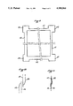
- FIG. 4 a schematic view of a curtain wall panel equipped with the sealing section, according to the invention.
- FIG. 5 an enlarged view of a curtain wall panel collar showing the widening of the sealing section to improve the tiling at right angles with the zones of juxtaposition of four panels;
- FIG. 6 a view in section of another form of realization of a sealing system, according to the invention.
- FIG. 7 a view in section of an example of realization of a packing disposed between two curtain wall panels, according to the invention.
- FIG. 8 a view in section of another example of realization of a packing disposed between two curtain wall panels, according to the invention.
- FIG. 9 a schematic view of the exterior of a rubber frame, only the outer lip of which is shown;
- FIG. 10 an exploded view in section of the overlap zone between four adjacent panels
- FIG. 11 a view in section according to FIG. 10, the panels being effectively in place to constitute the curtain wall.
- FIG. 1 one sees in horizontal section two adjacent panels 21 and 22 of a curtain wall.
- the inner face of these panels bears the references 23 and 24 respectively.
- the inner seal is ensured by two tubular sections, not symmetrical with one another, 25 and 26, or by a tubular section and a lipped section in lateral support.
- the outer seal is ensured by two sections, symmetrical with one another, 27 and 28, whose structure will be described later on.
- the faces 23 and 24 of the panels are the outer faces.
- the outer sealing section is composed of a hook-on foot 1 with lateral shoulders 2, 3 ensuring its hooking in a metal or other section, schematized at 4.
- This section of metal for example, presents two turned-up fins 5 and 6, behind which the shoulders 2 and 3 place themselves.
- the outer sealing section presents, in front of its hook-on foot 1, two lips 7 and 8 disposed, like the arms of a U. Lip 7 is long and lip 8 is short. Each of these lips presents a rear shoulder 9, 10, taking support on the fins 5, 6, respectively, of the metal section 4. In position of rest, the short lip 8 is substantially perpendicular to the plane of the fins 5, 6 of the metal section 4, and the long lip 7 is preferably slightly inclined toward the short lip 8.
- the outer sealing section according to the invention is made of elastically deformable material, for example of rubber or the like, or of thermoplastic product.
- the long lips 7, 7' take support on the outside of the short lips 8', 8, respectively, becoming elastically deformed. Because of this elastic deformation, the long lips 7, 7' are urged toward the short lips 8', 8 on which they remain applied, thus ensuring tightness between the panels of the curtain wall.
- the inner face of the long lip 7 is flat to ensure a better tight support on the short lip 8'.
- the sealing section according to the invention is manufactured in the form of a frame with vulcanized or glued corners, and placed around a panel, preferably at the factory, but to facilitate the positioning, two adjacent edges of the panel are fitted with a section with the long lip toward the outside (position 7') and the other two adjacent edges are fitted with a section with the long lip toward the inside (position 7).
- FIG. 4 symbolizes this arrangement.
- the right panel can be positioned by simple presentation from the outside.
- the two tight supports of the long lips 7, 7' on the short lips 8', 8 being realized automatically.
- FIG. 5 represents schematically such a widening 13, between a section with short lip 11 and a section with long lip 12, of the sealing system according to the invention. This widening is made at the factory, at the time of assembly by vulcanization for example, of the sections intended to constitute the sealing frame to be placed on each panel.
- the inner face of the panels is again represented at 23 and 24.
- the outer seal is ensured by two identical tubular sections 31 and 32 in reciprocal lateral support, and the inner seal is ensured by U-shaped sections, 33 and 34, in the arrangement of FIG. 3.
- the outer seal is ensured by two U-shaped sections 35 and 36, in the arrangement of FIG. 3, and the inner seal is ensured by a section 37 with short lip and a section 38 with long lip, in reciprocal support. All these sections are positioned at the factory, the asymmetrical U-shaped sections being placed either toward the outside or toward the inside of the curtain wall panels.
- FIG. 9 is schematized a frame of rubber, for example, only the outer lip of which is shown.
- the rubber section presents toward the outside a short lip on the sides 41 and 42 and a long lip on the sides 43 and 44.
- Each corner of the frame presents a widening, respectively 45 at the upper right, 46 at the upper left, 47 at the lower right, 48 at the lower left, the panel being seen from the outside.
- 45, 46, 47, 48 When positioning the panels, one finds at a crossing four corners with their widenings superposed in the order represented in FIG. 10: 45, 46, 47, 48.
- the two corners 46 and 47 are flat and flexible, and the two corners 45 and 48 are relatively rigid and curved.
- the curtain wall panels are equipped entirely at the factory with their two sealing frames, inner and outer respectively.
- the positioning of the panels in a certain order ensures correlatively the correct and definitive positioning of the sealing system, both inner and cuter. It is no longer necessary to provide an intervention on the face, for the positioning of the sealing sections.
Abstract
Description
Claims (16)
Applications Claiming Priority (1)
| Application Number | Priority Date | Filing Date | Title |
|---|---|---|---|
| FR8609387A FR2600695B1 (en) | 1986-06-27 | 1986-06-27 | CURTAIN WALL PANEL WITH SEALING SYSTEM, SEALING SYSTEM, AND CORRESPONDING PROFILE |
Publications (1)
| Publication Number | Publication Date |
|---|---|
| US4999960A true US4999960A (en) | 1991-03-19 |
Family
ID=9336824
Family Applications (1)
| Application Number | Title | Priority Date | Filing Date |
|---|---|---|---|
| US07/358,344 Expired - Fee Related US4999960A (en) | 1986-06-27 | 1987-07-01 | Curtain wall panel with sealing system, sealing system, and respective section |
Country Status (7)
| Country | Link |
|---|---|
| US (1) | US4999960A (en) |
| EP (1) | EP0297192B1 (en) |
| AT (1) | ATE67262T1 (en) |
| DE (1) | DE3772986D1 (en) |
| ES (1) | ES2026189T3 (en) |
| FR (1) | FR2600695B1 (en) |
| WO (1) | WO1989000222A1 (en) |
Cited By (36)
| Publication number | Priority date | Publication date | Assignee | Title |
|---|---|---|---|---|
| US5154029A (en) * | 1990-11-20 | 1992-10-13 | Canadian Rain Screen Technologies, Ltd. | Self-draining building panel system |
| US5339578A (en) * | 1991-10-09 | 1994-08-23 | Aerofoam Chemicals, Division Of Border Chemical Company | Support form for a grade beam or slab |
| US5709056A (en) * | 1995-07-21 | 1998-01-20 | Ykk Corporation | Cladding units for building and seal structure for joint thereof |
| US5845440A (en) * | 1995-07-21 | 1998-12-08 | Ykk Corporation | Cladding units for building and seal structure for joint thereof |
| US6442907B1 (en) * | 1998-02-23 | 2002-09-03 | 9068-4283 Quebec Inc. | Window case |
| US20050155322A1 (en) * | 1998-04-09 | 2005-07-21 | Robert Kroie | Building elements |
| US20070028538A1 (en) * | 2005-08-02 | 2007-02-08 | Clad Engineering | Glazing system |
| US20080276553A1 (en) * | 2007-04-11 | 2008-11-13 | Erla Dogg Ingjaldsdottir | Affordable, sustainable buildings comprised of recyclable materials and methods thereof |
| US20100263314A1 (en) * | 2005-11-14 | 2010-10-21 | Macdonald Robert B | Dry Joint Wall Panel Attachment System |
| US20110214361A1 (en) * | 2007-04-11 | 2011-09-08 | Erla Dogg Ingjaldsdottir | Affordable, sustainable buildings comprised of recyclable materials and methods thereof |
| US20120186170A1 (en) * | 2010-07-02 | 2012-07-26 | Macdonald Phil A | Wall Panel Systems for Rigid Wall Panels |
| US8745941B2 (en) | 2011-02-08 | 2014-06-10 | Robert B. MacDonald | Method for installing wall panels to the exterior wall of a building |
| US20140196394A1 (en) * | 2013-01-11 | 2014-07-17 | Chatsworth Products, Inc. | Modular thermal isolation barrier for data processing equipment structure |
| US20150020468A1 (en) * | 2013-07-16 | 2015-01-22 | Benjamin D. Wickstrom | Cleanroom wall panel system, and method |
| US20150276060A1 (en) * | 2014-03-25 | 2015-10-01 | M.G. McGrath, Inc. | Self-healing mate line for modular paneling |
| USD744667S1 (en) | 2011-12-19 | 2015-12-01 | Exterior Wall Systems Ltd. | Panel attachment extrusion with key |
| USD822471S1 (en) | 2017-02-07 | 2018-07-10 | Exterior Wall Systems Limited | Key for panel perimeter clips |
| USD823485S1 (en) | 2017-01-31 | 2018-07-17 | Exterior Wall Systems Limited | Panel stiffener for wall panel system |
| USD823666S1 (en) | 2017-01-31 | 2018-07-24 | Exterior Wall Systems Limited | Two-legged cube connector for wall panel system |
| USD823669S1 (en) | 2017-01-31 | 2018-07-24 | Exterior Wall Systems Limited | Five-way cube connector for wall panel system |
| USD823668S1 (en) | 2017-01-31 | 2018-07-24 | Exterior Wall Systems Limited (Ontario Panelization) | Pyramid cap connector for wall panel system |
| USD823670S1 (en) | 2017-01-31 | 2018-07-24 | Exterior Wall Systems Limited | Two-legged cube connector for wall panel system |
| USD823667S1 (en) | 2017-01-31 | 2018-07-24 | Exterior Wall Systems Limited | Three-legged cube connector for wall panel system |
| US10036156B1 (en) | 2017-01-31 | 2018-07-31 | Exterior Wall Systems Limited | Method of forming a three-dimensional structure having rigid wall panels |
| USD826030S1 (en) | 2017-01-31 | 2018-08-21 | Exterior Wall Systems Limited | Diamond pyramid diagonal leg for wall panel system |
| USD826692S1 (en) | 2017-01-31 | 2018-08-28 | Exterior Wall Systems Limited | Four-way cube connector for wall panel system |
| USD827416S1 (en) | 2017-01-31 | 2018-09-04 | Exterior Wall Systems Limited | Three-legged cube connector for wall panel system |
| USD827415S1 (en) | 2017-01-31 | 2018-09-04 | Exterior Wall Systems Limited | Box pyramid perimeter strip for wall panel system |
| USD827414S1 (en) | 2017-01-31 | 2018-09-04 | Exterior Wall Systems Limited | Pyramid corner connector for wall panel system |
| USD828142S1 (en) | 2017-01-31 | 2018-09-11 | Exterior Wall Systems Limited | Perimeter strip for wall panel system |
| USD831465S1 (en) | 2017-01-31 | 2018-10-23 | Exterior Wall Systems Limited (Ontario Panelization) | Box panel stiffener for wall panel system |
| USD831464S1 (en) | 2017-01-31 | 2018-10-23 | Exterior Wall Systems Limited | Box connector for wall panel system |
| USD839075S1 (en) | 2017-01-31 | 2019-01-29 | Exterior Wall Systems Limited | Tee cube connector for wall panel system |
| US11459751B2 (en) * | 2017-07-12 | 2022-10-04 | Dirtt Environmental Solutions Ltd | Wall seal |
| US20230250630A1 (en) * | 2020-10-09 | 2023-08-10 | China Construction Science And Industry Corporation Ltd. | Slab joint leakage-proof structure, prefabricated roof panel, and prefabricated roof panel system |
| US11885118B1 (en) | 2020-09-02 | 2024-01-30 | CDM Capital Asset Group, Inc. | Gasket for prefabricated wall panel systems |
Families Citing this family (7)
| Publication number | Priority date | Publication date | Assignee | Title |
|---|---|---|---|---|
| FR2636368B1 (en) * | 1988-09-15 | 1990-12-14 | Rubberia Sa | METHOD AND SEAL FOR A REVERSE CURVING SENSE LIPSTICK |
| GB8926808D0 (en) * | 1989-11-28 | 1990-01-17 | Coseley Building Systems Ltd | A cladding panel and system |
| DE4022528A1 (en) * | 1990-07-16 | 1992-01-23 | Mbs Gemont Ag | CURTAINED FACADE IN ELEMENT DESIGN |
| FR2729410B1 (en) * | 1995-01-17 | 1997-03-14 | Ed Penbat | SEALING DEVICE BETWEEN CURTAIN WALL ELEMENTS |
| FR2754286B1 (en) * | 1996-10-08 | 1998-12-31 | Monopanel Sa | FACADE ELEMENT WITH DECORATIVE SIDING |
| DE102009052359A1 (en) * | 2009-11-07 | 2011-05-12 | Eduard Hueck Gmbh & Co. Kg | element facade |
| CN102953432B (en) * | 2011-08-18 | 2016-09-21 | 上海美特幕墙有限公司 | A kind of vertical adhesive tape for waterproof interface of cell curtain wall |
Citations (18)
| Publication number | Priority date | Publication date | Assignee | Title |
|---|---|---|---|---|
| US1366470A (en) * | 1920-01-23 | 1921-01-25 | Henry H Lampert | Wall-tie |
| US2576296A (en) * | 1947-09-25 | 1951-11-27 | Lee B Green | Joint construction for panels |
| US3082848A (en) * | 1958-12-03 | 1963-03-26 | Robert R Keller | Multiple-panel load-bearing building walls and load-bearing panel units therefor |
| US3124222A (en) * | 1964-03-10 | Wall panel | ||
| US3341975A (en) * | 1965-04-07 | 1967-09-19 | Clark Equipment Co | Door seal construction |
| GB1121691A (en) * | 1965-02-17 | 1968-07-31 | B H Technical Developments Ltd | Improvements in pivoted windows |
| US3526071A (en) * | 1969-02-17 | 1970-09-01 | Kogyo Gomu Co Ltd | Panel for curtain walls and method of jointing corners of the same |
| US3555755A (en) * | 1968-11-20 | 1971-01-19 | Kalwall Corp | Overlap joint for translucent wall panels |
| FR2140336A1 (en) * | 1971-06-11 | 1973-01-19 | Voisin Roger | |
| US3722157A (en) * | 1971-03-15 | 1973-03-27 | Fruehauf Corp | Panel assembly system |
| US3817011A (en) * | 1973-01-18 | 1974-06-18 | Stackaruk F | Prefabricated interlocking wall panel |
| GB1467380A (en) * | 1974-03-21 | 1977-03-16 | Jahn Treske Gmbh Co Eurofit Kg | Joint seals |
| US4107892A (en) * | 1977-07-27 | 1978-08-22 | Butler Manufacturing Company | Wall panel unit |
| FR2533001A1 (en) * | 1982-09-10 | 1984-03-16 | Daetwyler France | Method for ensuring leaktightness at the centre of a cross formed by four woodwork frameworks, and corresponding sealing joint. |
| GB2130277A (en) * | 1982-11-18 | 1984-05-31 | Cmc Bodies Limited | Seals |
| GB2139668A (en) * | 1983-05-13 | 1984-11-14 | Yoshida Kogyo Kk | Joint assembly of horizontally opposed curtain wall units |
| US4744185A (en) * | 1985-01-22 | 1988-05-17 | Philippe Lamberet | Edge profile for insulating panel |
| US4824289A (en) * | 1986-08-08 | 1989-04-25 | Phoenix Aktiengesellschaft | Sealing profile for tunnel segments |
-
1986
- 1986-06-27 FR FR8609387A patent/FR2600695B1/en not_active Expired - Fee Related
-
1987
- 1987-06-30 ES ES198787401514T patent/ES2026189T3/en not_active Expired - Lifetime
- 1987-06-30 EP EP87401514A patent/EP0297192B1/en not_active Expired - Lifetime
- 1987-06-30 AT AT87401514T patent/ATE67262T1/en not_active IP Right Cessation
- 1987-06-30 DE DE8787401514T patent/DE3772986D1/en not_active Expired - Fee Related
- 1987-07-01 WO PCT/FR1987/000258 patent/WO1989000222A1/en unknown
- 1987-07-01 US US07/358,344 patent/US4999960A/en not_active Expired - Fee Related
Patent Citations (18)
| Publication number | Priority date | Publication date | Assignee | Title |
|---|---|---|---|---|
| US3124222A (en) * | 1964-03-10 | Wall panel | ||
| US1366470A (en) * | 1920-01-23 | 1921-01-25 | Henry H Lampert | Wall-tie |
| US2576296A (en) * | 1947-09-25 | 1951-11-27 | Lee B Green | Joint construction for panels |
| US3082848A (en) * | 1958-12-03 | 1963-03-26 | Robert R Keller | Multiple-panel load-bearing building walls and load-bearing panel units therefor |
| GB1121691A (en) * | 1965-02-17 | 1968-07-31 | B H Technical Developments Ltd | Improvements in pivoted windows |
| US3341975A (en) * | 1965-04-07 | 1967-09-19 | Clark Equipment Co | Door seal construction |
| US3555755A (en) * | 1968-11-20 | 1971-01-19 | Kalwall Corp | Overlap joint for translucent wall panels |
| US3526071A (en) * | 1969-02-17 | 1970-09-01 | Kogyo Gomu Co Ltd | Panel for curtain walls and method of jointing corners of the same |
| US3722157A (en) * | 1971-03-15 | 1973-03-27 | Fruehauf Corp | Panel assembly system |
| FR2140336A1 (en) * | 1971-06-11 | 1973-01-19 | Voisin Roger | |
| US3817011A (en) * | 1973-01-18 | 1974-06-18 | Stackaruk F | Prefabricated interlocking wall panel |
| GB1467380A (en) * | 1974-03-21 | 1977-03-16 | Jahn Treske Gmbh Co Eurofit Kg | Joint seals |
| US4107892A (en) * | 1977-07-27 | 1978-08-22 | Butler Manufacturing Company | Wall panel unit |
| FR2533001A1 (en) * | 1982-09-10 | 1984-03-16 | Daetwyler France | Method for ensuring leaktightness at the centre of a cross formed by four woodwork frameworks, and corresponding sealing joint. |
| GB2130277A (en) * | 1982-11-18 | 1984-05-31 | Cmc Bodies Limited | Seals |
| GB2139668A (en) * | 1983-05-13 | 1984-11-14 | Yoshida Kogyo Kk | Joint assembly of horizontally opposed curtain wall units |
| US4744185A (en) * | 1985-01-22 | 1988-05-17 | Philippe Lamberet | Edge profile for insulating panel |
| US4824289A (en) * | 1986-08-08 | 1989-04-25 | Phoenix Aktiengesellschaft | Sealing profile for tunnel segments |
Cited By (49)
| Publication number | Priority date | Publication date | Assignee | Title |
|---|---|---|---|---|
| US5154029A (en) * | 1990-11-20 | 1992-10-13 | Canadian Rain Screen Technologies, Ltd. | Self-draining building panel system |
| US5339578A (en) * | 1991-10-09 | 1994-08-23 | Aerofoam Chemicals, Division Of Border Chemical Company | Support form for a grade beam or slab |
| US5709056A (en) * | 1995-07-21 | 1998-01-20 | Ykk Corporation | Cladding units for building and seal structure for joint thereof |
| US5845440A (en) * | 1995-07-21 | 1998-12-08 | Ykk Corporation | Cladding units for building and seal structure for joint thereof |
| US5934033A (en) * | 1995-07-21 | 1999-08-10 | Ykk Corporation | Cladding units for building and seal structure for joint thereof |
| US6442907B1 (en) * | 1998-02-23 | 2002-09-03 | 9068-4283 Quebec Inc. | Window case |
| US20050155322A1 (en) * | 1998-04-09 | 2005-07-21 | Robert Kroie | Building elements |
| US20070028538A1 (en) * | 2005-08-02 | 2007-02-08 | Clad Engineering | Glazing system |
| US8166716B2 (en) | 2005-11-14 | 2012-05-01 | Macdonald Robert B | Dry joint wall panel attachment system |
| US20100263314A1 (en) * | 2005-11-14 | 2010-10-21 | Macdonald Robert B | Dry Joint Wall Panel Attachment System |
| US8429871B2 (en) | 2007-04-11 | 2013-04-30 | Erla Dögg Ingjaldsdottir | Affordable, sustainable buildings comprised of recyclable materials and methods thereof |
| US7941975B2 (en) * | 2007-04-11 | 2011-05-17 | Erla Dogg Ingjaldsdottir | Affordable, sustainable buildings comprised of recyclable materials and methods thereof |
| US20080276553A1 (en) * | 2007-04-11 | 2008-11-13 | Erla Dogg Ingjaldsdottir | Affordable, sustainable buildings comprised of recyclable materials and methods thereof |
| US20110214361A1 (en) * | 2007-04-11 | 2011-09-08 | Erla Dogg Ingjaldsdottir | Affordable, sustainable buildings comprised of recyclable materials and methods thereof |
| US9068358B2 (en) * | 2010-07-02 | 2015-06-30 | Exterior Wall Systems Limited | Wall panel systems for rigid wall panels |
| US20120186170A1 (en) * | 2010-07-02 | 2012-07-26 | Macdonald Phil A | Wall Panel Systems for Rigid Wall Panels |
| US8745941B2 (en) | 2011-02-08 | 2014-06-10 | Robert B. MacDonald | Method for installing wall panels to the exterior wall of a building |
| USD744667S1 (en) | 2011-12-19 | 2015-12-01 | Exterior Wall Systems Ltd. | Panel attachment extrusion with key |
| US9795060B2 (en) | 2013-01-11 | 2017-10-17 | Chatsworth Products, Inc. | Modular thermal isolation barrier for data processing equipment structure |
| US9572286B2 (en) | 2013-01-11 | 2017-02-14 | Chatsworth Products, Inc. | Modular thermal isolation barrier for data processing equipment structure |
| US20140196394A1 (en) * | 2013-01-11 | 2014-07-17 | Chatsworth Products, Inc. | Modular thermal isolation barrier for data processing equipment structure |
| US11647610B2 (en) * | 2013-01-11 | 2023-05-09 | Chatsworth Products, Inc. | Modular thermal isolation barrier for data processing equipment structure |
| US20220061188A1 (en) * | 2013-01-11 | 2022-02-24 | Chatsworth Products, Inc. | Modular thermal isolation barrier for data processing equipment structure |
| US10595442B2 (en) | 2013-01-11 | 2020-03-17 | Chatsworth Products, Inc. | Data processing equipment structure |
| US10375861B2 (en) | 2013-01-11 | 2019-08-06 | Chatsworth Products, Inc. | Modular thermal isolation barrier for data processing equipment structure |
| US9169641B2 (en) * | 2013-07-16 | 2015-10-27 | Erhardt Construction Company | Cleanroom wall panel system, and method |
| US20150020468A1 (en) * | 2013-07-16 | 2015-01-22 | Benjamin D. Wickstrom | Cleanroom wall panel system, and method |
| US20150276060A1 (en) * | 2014-03-25 | 2015-10-01 | M.G. McGrath, Inc. | Self-healing mate line for modular paneling |
| US10385973B2 (en) * | 2014-03-25 | 2019-08-20 | M.G. McGrath, Inc. | Self-healing mate line for modular paneling |
| USD827414S1 (en) | 2017-01-31 | 2018-09-04 | Exterior Wall Systems Limited | Pyramid corner connector for wall panel system |
| USD831465S1 (en) | 2017-01-31 | 2018-10-23 | Exterior Wall Systems Limited (Ontario Panelization) | Box panel stiffener for wall panel system |
| US10036156B1 (en) | 2017-01-31 | 2018-07-31 | Exterior Wall Systems Limited | Method of forming a three-dimensional structure having rigid wall panels |
| USD826030S1 (en) | 2017-01-31 | 2018-08-21 | Exterior Wall Systems Limited | Diamond pyramid diagonal leg for wall panel system |
| USD826692S1 (en) | 2017-01-31 | 2018-08-28 | Exterior Wall Systems Limited | Four-way cube connector for wall panel system |
| USD827416S1 (en) | 2017-01-31 | 2018-09-04 | Exterior Wall Systems Limited | Three-legged cube connector for wall panel system |
| USD827415S1 (en) | 2017-01-31 | 2018-09-04 | Exterior Wall Systems Limited | Box pyramid perimeter strip for wall panel system |
| USD823670S1 (en) | 2017-01-31 | 2018-07-24 | Exterior Wall Systems Limited | Two-legged cube connector for wall panel system |
| USD828142S1 (en) | 2017-01-31 | 2018-09-11 | Exterior Wall Systems Limited | Perimeter strip for wall panel system |
| USD823667S1 (en) | 2017-01-31 | 2018-07-24 | Exterior Wall Systems Limited | Three-legged cube connector for wall panel system |
| USD831464S1 (en) | 2017-01-31 | 2018-10-23 | Exterior Wall Systems Limited | Box connector for wall panel system |
| USD839075S1 (en) | 2017-01-31 | 2019-01-29 | Exterior Wall Systems Limited | Tee cube connector for wall panel system |
| USD823668S1 (en) | 2017-01-31 | 2018-07-24 | Exterior Wall Systems Limited (Ontario Panelization) | Pyramid cap connector for wall panel system |
| USD823669S1 (en) | 2017-01-31 | 2018-07-24 | Exterior Wall Systems Limited | Five-way cube connector for wall panel system |
| USD823666S1 (en) | 2017-01-31 | 2018-07-24 | Exterior Wall Systems Limited | Two-legged cube connector for wall panel system |
| USD823485S1 (en) | 2017-01-31 | 2018-07-17 | Exterior Wall Systems Limited | Panel stiffener for wall panel system |
| USD822471S1 (en) | 2017-02-07 | 2018-07-10 | Exterior Wall Systems Limited | Key for panel perimeter clips |
| US11459751B2 (en) * | 2017-07-12 | 2022-10-04 | Dirtt Environmental Solutions Ltd | Wall seal |
| US11885118B1 (en) | 2020-09-02 | 2024-01-30 | CDM Capital Asset Group, Inc. | Gasket for prefabricated wall panel systems |
| US20230250630A1 (en) * | 2020-10-09 | 2023-08-10 | China Construction Science And Industry Corporation Ltd. | Slab joint leakage-proof structure, prefabricated roof panel, and prefabricated roof panel system |
Also Published As
| Publication number | Publication date |
|---|---|
| FR2600695B1 (en) | 1991-03-15 |
| EP0297192A1 (en) | 1989-01-04 |
| EP0297192B1 (en) | 1991-09-11 |
| ATE67262T1 (en) | 1991-09-15 |
| DE3772986D1 (en) | 1991-10-17 |
| ES2026189T3 (en) | 1992-04-16 |
| FR2600695A1 (en) | 1987-12-31 |
| WO1989000222A1 (en) | 1989-01-12 |
Similar Documents
| Publication | Publication Date | Title |
|---|---|---|
| US4999960A (en) | Curtain wall panel with sealing system, sealing system, and respective section | |
| KR100739896B1 (en) | Improved sealing assembly for refrigerator cabinets and the like with a profile made of plastic material | |
| JPH0122832Y2 (en) | ||
| IE38501L (en) | Structural assembly | |
| JPH0415337B2 (en) | ||
| US4276729A (en) | Flashing construction for a curtain wall | |
| JP3871249B2 (en) | Joint structure of vertical and horizontal frames in curtain wall | |
| US4590725A (en) | System for sealing cross joint of four adjacent curtain wall units | |
| RU2279611C2 (en) | Improved sealing gasket for refrigerator accessories | |
| EP0432105B1 (en) | Aluminium section member building continuous front | |
| US2581574A (en) | Weather strip | |
| CN211312966U (en) | Modular frame system | |
| FR2650854B1 (en) | WOODEN FRAME COMPRISING A GROOVE FOR GLAZING | |
| JPS6228254B2 (en) | ||
| JP2663091B2 (en) | Double glazed curtain wall | |
| GB2304281A (en) | Plastics bath seal extrusion with extra lateral deflection | |
| US5800660A (en) | Method of producing entire frames made up of plastic profiles | |
| CN213418323U (en) | Panel piece system | |
| JP2523739Y2 (en) | Open joint structure of curtain wall | |
| JP2822115B2 (en) | Seal structure of directional connection | |
| JP3487226B2 (en) | Panel outer wall | |
| GB2241002A (en) | Building fascia panel | |
| US2739011A (en) | Vehicle windshield mounting | |
| JPH0734970Y2 (en) | Curtain wall open joint structure | |
| JP3197861B2 (en) | Gasket for window |
Legal Events
| Date | Code | Title | Description |
|---|---|---|---|
| AS | Assignment |
Owner name: FRANCE, DATWYLER, FRANCE Free format text: ASSIGNMENT OF 1/2 OF ASSIGNORS INTEREST;ASSIGNORS:HERWEGH, NORBERT;RAULET, DANIEL;AUBERT, CHARLES;REEL/FRAME:005174/0478;SIGNING DATES FROM 19890424 TO 19890426 Owner name: SOCIETE EN NOM COLLECTIF SACILOR & CIE, FRANCE Free format text: ASSIGNMENT OF 1/2 OF ASSIGNORS INTEREST;ASSIGNORS:HERWEGH, NORBERT;RAULET, DANIEL;AUBERT, CHARLES;REEL/FRAME:005174/0478;SIGNING DATES FROM 19890424 TO 19890426 |
|
| FEPP | Fee payment procedure |
Free format text: PAYOR NUMBER ASSIGNED (ORIGINAL EVENT CODE: ASPN); ENTITY STATUS OF PATENT OWNER: LARGE ENTITY |
|
| FPAY | Fee payment |
Year of fee payment: 4 |
|
| REMI | Maintenance fee reminder mailed | ||
| LAPS | Lapse for failure to pay maintenance fees | ||
| FP | Lapsed due to failure to pay maintenance fee |
Effective date: 19990319 |
|
| STCH | Information on status: patent discontinuation |
Free format text: PATENT EXPIRED DUE TO NONPAYMENT OF MAINTENANCE FEES UNDER 37 CFR 1.362 |