US4990082A - Vibrator with suction apparatus - Google Patents
Vibrator with suction apparatus Download PDFInfo
- Publication number
- US4990082A US4990082A US07/369,870 US36987089A US4990082A US 4990082 A US4990082 A US 4990082A US 36987089 A US36987089 A US 36987089A US 4990082 A US4990082 A US 4990082A
- Authority
- US
- United States
- Prior art keywords
- vibrator
- forming mold
- suction
- vacuum chamber
- suction disc
- Prior art date
- Legal status (The legal status is an assumption and is not a legal conclusion. Google has not performed a legal analysis and makes no representation as to the accuracy of the status listed.)
- Expired - Fee Related
Links
- 238000012856 packing Methods 0.000 claims 1
- 238000005086 pumping Methods 0.000 claims 1
- 238000000034 method Methods 0.000 description 6
- 230000008569 process Effects 0.000 description 6
- 238000010276 construction Methods 0.000 description 4
- 238000009434 installation Methods 0.000 description 2
- 230000007246 mechanism Effects 0.000 description 2
- 230000002093 peripheral effect Effects 0.000 description 2
- 229910000831 Steel Inorganic materials 0.000 description 1
- 230000009471 action Effects 0.000 description 1
- 238000004891 communication Methods 0.000 description 1
- 238000010586 diagram Methods 0.000 description 1
- 238000012986 modification Methods 0.000 description 1
- 230000004048 modification Effects 0.000 description 1
- 230000003014 reinforcing effect Effects 0.000 description 1
- 239000010959 steel Substances 0.000 description 1
Images


Classifications
-
- E—FIXED CONSTRUCTIONS
- E04—BUILDING
- E04G—SCAFFOLDING; FORMS; SHUTTERING; BUILDING IMPLEMENTS OR AIDS, OR THEIR USE; HANDLING BUILDING MATERIALS ON THE SITE; REPAIRING, BREAKING-UP OR OTHER WORK ON EXISTING BUILDINGS
- E04G21/00—Preparing, conveying, or working-up building materials or building elements in situ; Other devices or measures for constructional work
- E04G21/02—Conveying or working-up concrete or similar masses able to be heaped or cast
- E04G21/06—Solidifying concrete, e.g. by application of vacuum before hardening
- E04G21/063—Solidifying concrete, e.g. by application of vacuum before hardening making use of vibrating or jolting tools
- E04G21/065—Solidifying concrete, e.g. by application of vacuum before hardening making use of vibrating or jolting tools acting upon the shuttering
Definitions
- the present invention relates to an improved vibrator with suction apparatus, and more particularly to a vibrator used in architecture or civil engineering use.
- the vibrator 10 includes a vibrating apparatus 11 and a positioning apparatus 12 which further consists of a fixed jaw 121 and a moving jaw 122 for clamping onto the ribs 13 of the mold in a manner as shown in FIGS. 1 and 2.
- the vibrator 10 is advantageous in its attachment to the mold because said vibrator uses the positioning apparatus 12 to clamp onto the ribs 13 of the mold, the attachment of said vibrator 10 is impossible if there are no reinforcing ribs on the forming molds.
- the most important advantages of the improved vibrator of the present invention are ease of installation onto the forming mold of the concrete and convenience of portability to enable the same to be easily transported from place to place. Therefore, only one set of the vibrators of this invention will be sufficient to treat a forming mold with relatively large surface area.
- An object, as well as an important feature, of the vibrator of the present invention is to provide a suction apparatus on the improved vibrator to enable the easy attachment of the same onto a forming mold.
- the improved vibrator of this invention comprises a vibrating means and a suction means integrally formed with said vibrating means, which is substantially in the shape of a disc with a flexible peripheral lip portion and a low pressure chamber portion for resulting in air tight attachment onto the forming mold.
- FIG. 1 is a schematic front view of the conventional auromatic rotation vibrator.
- FIG. 2 is a perspective view showing a conventional automatic rotation vibrator installed onto the ribs of a forming mold.
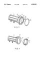
- FIG. 3 is an exploded perspective of a first embodiment of the improved vibrator of the invention.
- FIG. 4 is an exploded perspective view of a second embodiment of the improved vibrator of the invention.
- the vibrator 20 comprises a vibrating means 21, which can be a conventional reciprocal or rotational vibrating mechanism, and a suction means 22 integrally formed with the vibrating means 21. Since the vibrating means 21 has a conventional structure and merely performs a vibration function, it will not be detailed for the purpose of simplicity. Those who are skilled in the art of such vibrating mechanisms, will be able to duplicate such a vibrating means 21.
- the suction means 22 substantially comprises a body 24 in the shape of a disc having a lip portion 23 at the periphery thereof.
- the lip portion 23 includes two concentric annular flanges 231, 232 with a flexible gasket 233 clamped therebetween.
- the gasket 233 will deform a little bit while being connected with the surface of the forming mold so as to form an air tight attachment thereto.
- An air passage 25 is formed on the disc body 24 in communication with an adaptor 26 which is formed on the back side of the disc body 24.
- a control switch 27 is provided at the vicinity of the adaptor 26.
- the vibrator 20 is positioned on an area on the outer surface of a forming mold where vibration is to be applied.
- An air pump is then operated with the pipe thereof connected to the adaptor 26 of the vibrator 20.
- the interior of the disc body 24 will become a low pressure area due to the action of the air pump.
- the suction means 21, with the gasket 233 thereof in contact with the forming mold tightly attaches to the mold by means of suction.
- the air pump remains operating during the vibration process.
- there is perfect surface-to-surface contact between the gasket 233 and the forming mold one can turn off the control switch 27 after the air tight attachment is achieved.
- the vibrator 20 of this invention can be very easily removed from the forming mold by stopping the operation of the air pump or turning on the control switch 27.
- the vibrator 20 may then be transported to another location on the forming mold to continue the vibration process.
- FIG. 4 shows another embodiment of the improved vibrator of this invention.
- the vibrator has a structure which is substantially the same as that of the vibrator shown in FIG. 3, in terms of the vibrating means 21 and the suction means 22 thereof.
- the flexible gasket 31 comprises a base 311 with a horn-like rim portion 312 extending therefrom for achieving an ideal air tight contact with the forming mold.
- the operation of this embodiment of the vibrator is exactly the same as that of the vibrator shown in FIG. 3.
Landscapes
- Engineering & Computer Science (AREA)
- Architecture (AREA)
- Mechanical Engineering (AREA)
- Civil Engineering (AREA)
- Structural Engineering (AREA)
- Reciprocating Pumps (AREA)
Abstract
An improved vibrator for architectural or civil engineering use is disclosed. The vibrator includes a vibrating means which is either a conventional reciprocating or rotating vibrator, and a suction means which is integrally formed with the vibrating means and has at least one suction member to be attached to the forming molds. The suction means of the improved vibrator enables an air tight connection between the vibrator and the forming molds. The suction means is substantially in the shape of a disc with an air passage formed therein to be operated via an air pump to produce a low pressure area in the disc body. The suction member comprises at least one flexible gasket at the periphery of the disc body which is attached to the forming mold to form an ideal attachment.
Description
The present invention relates to an improved vibrator with suction apparatus, and more particularly to a vibrator used in architecture or civil engineering use.
In the ordinary process for architecture or civil engineering, especially those concerned with the construction of a building, vibrators are attached onto a concrete mold to drive out any possible air bubbles remaining within the freshly poured concrete. This vibration process is one of the standard processes for achieving construction of good quality. The greater the amount of vibration applied on the freshly poured concrete, the stronger the construction and the finer the outer surface thereof will be when said concrete dries.
The difficulties encountered in the use of a conventional vibrator are the time and labor-consumption required for installation, the need for the use of many sets of vibrators to manipulate the poured concrete confined in a single set of molds, and the inconvenience in detaching the vibrator from the mold, etc. In addition, it is unavoidably necessary to equip a seat member on the mold so that the vibrator may be installed thereon to avoid possible damage to the mold itself. This is true when using a steel mold for constructing a building.
Automatic rotation vibrators, abbreviated as ARV's, were developed several years ago and protected by U.S. Pat. Nos. 4,579,697 and 4,580,456. The front schematic diagram of an automatic rotation vibrator is shown in FIG. 1, and a perspective view of the same when attached on the ribs of a mold is shown in FIG. 2. The vibrator 10 includes a vibrating apparatus 11 and a positioning apparatus 12 which further consists of a fixed jaw 121 and a moving jaw 122 for clamping onto the ribs 13 of the mold in a manner as shown in FIGS. 1 and 2. Although the vibrator 10 is advantageous in its attachment to the mold because said vibrator uses the positioning apparatus 12 to clamp onto the ribs 13 of the mold, the attachment of said vibrator 10 is impossible if there are no reinforcing ribs on the forming molds.
It is therefore the principle object of the present invention to provide an improved vibrator which is particularly suitable for use in architectural or civil engineering constructions and overcomes the disadvantages of the conventional vibrators.
The most important advantages of the improved vibrator of the present invention are ease of installation onto the forming mold of the concrete and convenience of portability to enable the same to be easily transported from place to place. Therefore, only one set of the vibrators of this invention will be sufficient to treat a forming mold with relatively large surface area.
An object, as well as an important feature, of the vibrator of the present invention is to provide a suction apparatus on the improved vibrator to enable the easy attachment of the same onto a forming mold.
Accordingly, the improved vibrator of this invention comprises a vibrating means and a suction means integrally formed with said vibrating means, which is substantially in the shape of a disc with a flexible peripheral lip portion and a low pressure chamber portion for resulting in air tight attachment onto the forming mold.
These and other advantages, objects and features of the improved vibrator of the invention will become apparent from the following detailed description of the preferred embodiments with reference to the accompanying drawings.
FIG. 1 is a schematic front view of the conventional auromatic rotation vibrator.
FIG. 2 is a perspective view showing a conventional automatic rotation vibrator installed onto the ribs of a forming mold.
FIG. 3 is an exploded perspective of a first embodiment of the improved vibrator of the invention.
FIG. 4 is an exploded perspective view of a second embodiment of the improved vibrator of the invention.
Referring to FIG. 3, which shows a perspective view of an improved vibrator of this invention, the vibrator 20 comprises a vibrating means 21, which can be a conventional reciprocal or rotational vibrating mechanism, and a suction means 22 integrally formed with the vibrating means 21. Since the vibrating means 21 has a conventional structure and merely performs a vibration function, it will not be detailed for the purpose of simplicity. Those who are skilled in the art of such vibrating mechanisms, will be able to duplicate such a vibrating means 21.
The suction means 22 substantially comprises a body 24 in the shape of a disc having a lip portion 23 at the periphery thereof. The lip portion 23 includes two concentric annular flanges 231, 232 with a flexible gasket 233 clamped therebetween. The gasket 233 will deform a little bit while being connected with the surface of the forming mold so as to form an air tight attachment thereto. An air passage 25 is formed on the disc body 24 in communication with an adaptor 26 which is formed on the back side of the disc body 24. A control switch 27 is provided at the vicinity of the adaptor 26.
In operation, the vibrator 20 is positioned on an area on the outer surface of a forming mold where vibration is to be applied. An air pump is then operated with the pipe thereof connected to the adaptor 26 of the vibrator 20. The interior of the disc body 24 will become a low pressure area due to the action of the air pump. The suction means 21, with the gasket 233 thereof in contact with the forming mold, tightly attaches to the mold by means of suction. In order to prevent any possible movement of the vibrator 20 on the forming mold, the air pump remains operating during the vibration process. Of course, if there is perfect surface-to-surface contact between the gasket 233 and the forming mold, one can turn off the control switch 27 after the air tight attachment is achieved.
After the vibration process is completed, the vibrator 20 of this invention can be very easily removed from the forming mold by stopping the operation of the air pump or turning on the control switch 27. The vibrator 20 may then be transported to another location on the forming mold to continue the vibration process.
FIG. 4 shows another embodiment of the improved vibrator of this invention. In this embodiment, the vibrator has a structure which is substantially the same as that of the vibrator shown in FIG. 3, in terms of the vibrating means 21 and the suction means 22 thereof. However, there is only one peripheral annular flange 30 at the lip portion 23 of the suction means. The flexible gasket 31 comprises a base 311 with a horn-like rim portion 312 extending therefrom for achieving an ideal air tight contact with the forming mold. The operation of this embodiment of the vibrator is exactly the same as that of the vibrator shown in FIG. 3.
Although this invention has been described by way of preferred embodiments, modifications and changes are still possible for those skilled in the art without departing from the spirit of the invention.
Claims (3)
1. A vibrator for packing freshly poured concrete confined in a forming mold comprising:
a vibrator body; and
a suction disc means serving to connect said vibrator body to the forming mold, said suction disc means having a rigid disc which has one end secured to said vibrator body and another end with an annular flange defining a vacuum chamber, and a flexible and resilient gasket to provide a gas-tight seal between the forming mold and said rigid disc, said gasket having a cylindrical portion disposed in a tight fit around said annular flange and having a horn-like annular flared portion extending from and inclining away from said cylindrical portion, said annular flared portion flexing from said cylindrical portion to an extent sufficient to place said annular flange of said rigid disc in contact with the forming mold when a vacuum is created in said vacuum chamber.
2. The vibrator as claimed in claim 1, wherein defined in said suction disc means is an air passage which communicates with said vacuum chamber and a point external to said vibrator, and wherein said vibrator further comprises an adapter formed on a surface of said vibrator and connected to said suction disc means, said adaptor being in alignment with said air passage.
3. A vibrator as claimed in claim 2, wherein said suction disc means further comprises a control switch provided in the vicinity of said adaptor for starting and stopping an air pumping operation of said suction means which creates a vacuum in said vacuum chamber.
Priority Applications (1)
| Application Number | Priority Date | Filing Date | Title |
|---|---|---|---|
| US07/369,870 US4990082A (en) | 1989-06-22 | 1989-06-22 | Vibrator with suction apparatus |
Applications Claiming Priority (1)
| Application Number | Priority Date | Filing Date | Title |
|---|---|---|---|
| US07/369,870 US4990082A (en) | 1989-06-22 | 1989-06-22 | Vibrator with suction apparatus |
Publications (1)
| Publication Number | Publication Date |
|---|---|
| US4990082A true US4990082A (en) | 1991-02-05 |
Family
ID=23457258
Family Applications (1)
| Application Number | Title | Priority Date | Filing Date |
|---|---|---|---|
| US07/369,870 Expired - Fee Related US4990082A (en) | 1989-06-22 | 1989-06-22 | Vibrator with suction apparatus |
Country Status (1)
| Country | Link |
|---|---|
| US (1) | US4990082A (en) |
Cited By (5)
| Publication number | Priority date | Publication date | Assignee | Title |
|---|---|---|---|---|
| US5198246A (en) * | 1990-09-27 | 1993-03-30 | Monoform, Inc. | Concrete molding device |
| US5484202A (en) * | 1995-02-01 | 1996-01-16 | Wisconsin Alumni Research Foundation | Aerosol containment system |
| US5932256A (en) * | 1996-09-27 | 1999-08-03 | Mandish; Theodore O. | Vacuum molding apparatus |
| US20120104214A1 (en) * | 2010-10-28 | 2012-05-03 | St Jacques Stefan | Stabilizing device |
| US9499085B2 (en) | 2013-06-25 | 2016-11-22 | Martin Engineering Company | Vibratory apparatus |
Citations (12)
| Publication number | Priority date | Publication date | Assignee | Title |
|---|---|---|---|---|
| US762499A (en) * | 1904-02-16 | 1904-06-14 | John Howard Sprague | Vacuum-lifter. |
| US799922A (en) * | 1905-01-17 | 1905-09-19 | Egbert Moxham | Head-setter. |
| US2783018A (en) * | 1955-02-11 | 1957-02-26 | Vac U Lift Company | Valve means for suction lifting devices |
| US2853333A (en) * | 1955-09-07 | 1958-09-23 | Littell Machine Co F J | Vacuum cup |
| US3152828A (en) * | 1962-02-02 | 1964-10-13 | Alvey Conveyor Mfg Co | Vacuum cup units for lifting pads |
| US3853345A (en) * | 1973-11-30 | 1974-12-10 | Us Navy | Suction gripping device |
| FR2262751A1 (en) * | 1974-02-28 | 1975-09-26 | Alkan R & Cie | Device securing workpieces to marble - has open cylinder with stepped piston creating partial vacuum |
| US3910620A (en) * | 1974-04-15 | 1975-10-07 | American Chain & Cable Co | High temperature vacuum pad lift |
| SU640952A1 (en) * | 1976-04-27 | 1979-01-05 | Предриятие П/Я Г-4778 | Suction-type load-engaging device |
| US4579697A (en) * | 1983-08-22 | 1986-04-01 | Kikumitsu Takano | Method for packing concrete cement utilizing a vibrator |
| US4580456A (en) * | 1983-04-14 | 1986-04-08 | Kikumithus Takano | Balance weight transfer device for a vibrator |
| DE3724659A1 (en) * | 1987-07-25 | 1989-02-02 | Pannkoke Karl | Sucker for vacuum lifting devices |
-
1989
- 1989-06-22 US US07/369,870 patent/US4990082A/en not_active Expired - Fee Related
Patent Citations (12)
| Publication number | Priority date | Publication date | Assignee | Title |
|---|---|---|---|---|
| US762499A (en) * | 1904-02-16 | 1904-06-14 | John Howard Sprague | Vacuum-lifter. |
| US799922A (en) * | 1905-01-17 | 1905-09-19 | Egbert Moxham | Head-setter. |
| US2783018A (en) * | 1955-02-11 | 1957-02-26 | Vac U Lift Company | Valve means for suction lifting devices |
| US2853333A (en) * | 1955-09-07 | 1958-09-23 | Littell Machine Co F J | Vacuum cup |
| US3152828A (en) * | 1962-02-02 | 1964-10-13 | Alvey Conveyor Mfg Co | Vacuum cup units for lifting pads |
| US3853345A (en) * | 1973-11-30 | 1974-12-10 | Us Navy | Suction gripping device |
| FR2262751A1 (en) * | 1974-02-28 | 1975-09-26 | Alkan R & Cie | Device securing workpieces to marble - has open cylinder with stepped piston creating partial vacuum |
| US3910620A (en) * | 1974-04-15 | 1975-10-07 | American Chain & Cable Co | High temperature vacuum pad lift |
| SU640952A1 (en) * | 1976-04-27 | 1979-01-05 | Предриятие П/Я Г-4778 | Suction-type load-engaging device |
| US4580456A (en) * | 1983-04-14 | 1986-04-08 | Kikumithus Takano | Balance weight transfer device for a vibrator |
| US4579697A (en) * | 1983-08-22 | 1986-04-01 | Kikumitsu Takano | Method for packing concrete cement utilizing a vibrator |
| DE3724659A1 (en) * | 1987-07-25 | 1989-02-02 | Pannkoke Karl | Sucker for vacuum lifting devices |
Cited By (7)
| Publication number | Priority date | Publication date | Assignee | Title |
|---|---|---|---|---|
| US5198246A (en) * | 1990-09-27 | 1993-03-30 | Monoform, Inc. | Concrete molding device |
| US5484202A (en) * | 1995-02-01 | 1996-01-16 | Wisconsin Alumni Research Foundation | Aerosol containment system |
| US5932256A (en) * | 1996-09-27 | 1999-08-03 | Mandish; Theodore O. | Vacuum molding apparatus |
| US6461551B1 (en) | 1996-09-27 | 2002-10-08 | Theodore O. Mandish | Vacuum molding process |
| US20120104214A1 (en) * | 2010-10-28 | 2012-05-03 | St Jacques Stefan | Stabilizing device |
| US8998158B2 (en) * | 2010-10-28 | 2015-04-07 | Staybowlizer Inc. | Stabilizing device for a receptacle or spherical object |
| US9499085B2 (en) | 2013-06-25 | 2016-11-22 | Martin Engineering Company | Vibratory apparatus |
Similar Documents
| Publication | Publication Date | Title |
|---|---|---|
| KR960015260B1 (en) | Grinder with dust exhaust means | |
| US6190245B1 (en) | Quarter pad sander | |
| US5932256A (en) | Vacuum molding apparatus | |
| US4990082A (en) | Vibrator with suction apparatus | |
| JPS6023696A (en) | Flexible sleeve for storage instrument activator | |
| JP2785060B2 (en) | Wall suction moving device | |
| JPH09184484A (en) | Pump diaphragm | |
| EP0141139B1 (en) | Suction housing for vacuum sanding devices | |
| US2749097A (en) | Vibrator | |
| US5433523A (en) | Vibrators | |
| JPH0137183Y2 (en) | ||
| CN211636299U (en) | Grinding wheel abrasive material mixer | |
| JPH03193169A (en) | Bolt cleaning device | |
| CN2072563U (en) | Construction vibrator with suction device | |
| JP3127565B2 (en) | Floor sweeper | |
| CN216736062U (en) | Rotary feeder with air seal device | |
| KR200327972Y1 (en) | Dust Collecting Cover Equipped with Hand Grinder | |
| CN223293394U (en) | Concrete pouring equipment for construction projects that is easy to adjust | |
| CN214462626U (en) | Aluminum alloy template assembling and disassembling tool | |
| CN210858021U (en) | Reinforced concrete inner support dismantling device | |
| CN223359411U (en) | A Roots vacuum pump with a detachable sleeve structure | |
| CN113737962B (en) | A partitioned grouting device for connection of assembled components and its application method | |
| JPH0634930Y2 (en) | Polishing equipment | |
| JP2002180667A (en) | Hand-held form vibrator | |
| JPH0434901Y2 (en) |
Legal Events
| Date | Code | Title | Description |
|---|---|---|---|
| FEPP | Fee payment procedure |
Free format text: PAYOR NUMBER ASSIGNED (ORIGINAL EVENT CODE: ASPN); ENTITY STATUS OF PATENT OWNER: SMALL ENTITY |
|
| FPAY | Fee payment |
Year of fee payment: 4 |
|
| FPAY | Fee payment |
Year of fee payment: 8 |
|
| REMI | Maintenance fee reminder mailed | ||
| LAPS | Lapse for failure to pay maintenance fees | ||
| FP | Lapsed due to failure to pay maintenance fee |
Effective date: 20030205 |
|
| STCH | Information on status: patent discontinuation |
Free format text: PATENT EXPIRED DUE TO NONPAYMENT OF MAINTENANCE FEES UNDER 37 CFR 1.362 |