US4988244A - Six-axis machine tool - Google Patents
Six-axis machine tool Download PDFInfo
- Publication number
- US4988244A US4988244A US07/572,167 US57216790A US4988244A US 4988244 A US4988244 A US 4988244A US 57216790 A US57216790 A US 57216790A US 4988244 A US4988244 A US 4988244A
- Authority
- US
- United States
- Prior art keywords
- legs
- leg
- platform
- length
- workpiece
- Prior art date
- Legal status (The legal status is an assumption and is not a legal conclusion. Google has not performed a legal analysis and makes no representation as to the accuracy of the status listed.)
- Expired - Fee Related
Links
Images


Classifications
-
- G—PHYSICS
- G05—CONTROLLING; REGULATING
- G05B—CONTROL OR REGULATING SYSTEMS IN GENERAL; FUNCTIONAL ELEMENTS OF SUCH SYSTEMS; MONITORING OR TESTING ARRANGEMENTS FOR SUCH SYSTEMS OR ELEMENTS
- G05B19/00—Program-control systems
- G05B19/02—Program-control systems electric
- G05B19/18—Numerical control [NC], i.e. automatically operating machines, in particular machine tools, e.g. in a manufacturing environment, so as to execute positioning, movement or co-ordinated operations by means of program data in numerical form
- G05B19/408—Numerical control [NC], i.e. automatically operating machines, in particular machine tools, e.g. in a manufacturing environment, so as to execute positioning, movement or co-ordinated operations by means of program data in numerical form characterised by data handling or data format, e.g. reading, buffering or conversion of data
- G05B19/4086—Coordinate conversions; Other special calculations
-
- B—PERFORMING OPERATIONS; TRANSPORTING
- B23—MACHINE TOOLS; METAL-WORKING NOT OTHERWISE PROVIDED FOR
- B23Q—DETAILS, COMPONENTS, OR ACCESSORIES FOR MACHINE TOOLS, e.g. ARRANGEMENTS FOR COPYING OR CONTROLLING; MACHINE TOOLS IN GENERAL CHARACTERISED BY THE CONSTRUCTION OF PARTICULAR DETAILS OR COMPONENTS; COMBINATIONS OR ASSOCIATIONS OF METAL-WORKING MACHINES, NOT DIRECTED TO A PARTICULAR RESULT
- B23Q1/00—Members which are comprised in the general build-up of a form of machine, particularly relatively large fixed members
- B23Q1/25—Movable or adjustable work or tool supports
- B23Q1/44—Movable or adjustable work or tool supports using particular mechanisms
- B23Q1/50—Movable or adjustable work or tool supports using particular mechanisms with rotating pairs only, the rotating pairs being the first two elements of the mechanism
- B23Q1/54—Movable or adjustable work or tool supports using particular mechanisms with rotating pairs only, the rotating pairs being the first two elements of the mechanism two rotating pairs only
- B23Q1/545—Movable or adjustable work or tool supports using particular mechanisms with rotating pairs only, the rotating pairs being the first two elements of the mechanism two rotating pairs only comprising spherical surfaces
- B23Q1/5462—Movable or adjustable work or tool supports using particular mechanisms with rotating pairs only, the rotating pairs being the first two elements of the mechanism two rotating pairs only comprising spherical surfaces with one supplementary sliding pair
-
- B—PERFORMING OPERATIONS; TRANSPORTING
- B23—MACHINE TOOLS; METAL-WORKING NOT OTHERWISE PROVIDED FOR
- B23Q—DETAILS, COMPONENTS, OR ACCESSORIES FOR MACHINE TOOLS, e.g. ARRANGEMENTS FOR COPYING OR CONTROLLING; MACHINE TOOLS IN GENERAL CHARACTERISED BY THE CONSTRUCTION OF PARTICULAR DETAILS OR COMPONENTS; COMBINATIONS OR ASSOCIATIONS OF METAL-WORKING MACHINES, NOT DIRECTED TO A PARTICULAR RESULT
- B23Q5/00—Driving or feeding mechanisms; Control arrangements therefor
- B23Q5/22—Feeding members carrying tools or work
- B23Q5/34—Feeding other members supporting tools or work, e.g. saddles, tool-slides, through mechanical transmission
- B23Q5/38—Feeding other members supporting tools or work, e.g. saddles, tool-slides, through mechanical transmission feeding continuously
- B23Q5/40—Feeding other members supporting tools or work, e.g. saddles, tool-slides, through mechanical transmission feeding continuously by feed shaft, e.g. lead screw
-
- B—PERFORMING OPERATIONS; TRANSPORTING
- B25—HAND TOOLS; PORTABLE POWER-DRIVEN TOOLS; MANIPULATORS
- B25J—MANIPULATORS; CHAMBERS PROVIDED WITH MANIPULATION DEVICES
- B25J17/00—Joints
- B25J17/02—Wrist joints
- B25J17/0208—Compliance devices
- B25J17/0216—Compliance devices comprising a stewart mechanism
-
- B—PERFORMING OPERATIONS; TRANSPORTING
- B25—HAND TOOLS; PORTABLE POWER-DRIVEN TOOLS; MANIPULATORS
- B25J—MANIPULATORS; CHAMBERS PROVIDED WITH MANIPULATION DEVICES
- B25J9/00—Program-controlled manipulators
- B25J9/16—Program controls
- B25J9/1615—Program controls characterised by special kind of manipulator, e.g. planar, scara, gantry, cantilever, space, closed chain, passive/active joints and tendon driven manipulators
- B25J9/1623—Parallel manipulator, Stewart platform, links are attached to a common base and to a common platform, plate which is moved parallel to the base
-
- G—PHYSICS
- G05—CONTROLLING; REGULATING
- G05B—CONTROL OR REGULATING SYSTEMS IN GENERAL; FUNCTIONAL ELEMENTS OF SUCH SYSTEMS; MONITORING OR TESTING ARRANGEMENTS FOR SUCH SYSTEMS OR ELEMENTS
- G05B19/00—Program-control systems
- G05B19/02—Program-control systems electric
- G05B19/18—Numerical control [NC], i.e. automatically operating machines, in particular machine tools, e.g. in a manufacturing environment, so as to execute positioning, movement or co-ordinated operations by means of program data in numerical form
- G05B19/19—Numerical control [NC], i.e. automatically operating machines, in particular machine tools, e.g. in a manufacturing environment, so as to execute positioning, movement or co-ordinated operations by means of program data in numerical form characterised by positioning or contouring control systems, e.g. to control position from one programmed point to another or to control movement along a programmed continuous path
- G05B19/21—Numerical control [NC], i.e. automatically operating machines, in particular machine tools, e.g. in a manufacturing environment, so as to execute positioning, movement or co-ordinated operations by means of program data in numerical form characterised by positioning or contouring control systems, e.g. to control position from one programmed point to another or to control movement along a programmed continuous path using an incremental digital measuring device
- G05B19/23—Numerical control [NC], i.e. automatically operating machines, in particular machine tools, e.g. in a manufacturing environment, so as to execute positioning, movement or co-ordinated operations by means of program data in numerical form characterised by positioning or contouring control systems, e.g. to control position from one programmed point to another or to control movement along a programmed continuous path using an incremental digital measuring device for point-to-point control
- G05B19/231—Numerical control [NC], i.e. automatically operating machines, in particular machine tools, e.g. in a manufacturing environment, so as to execute positioning, movement or co-ordinated operations by means of program data in numerical form characterised by positioning or contouring control systems, e.g. to control position from one programmed point to another or to control movement along a programmed continuous path using an incremental digital measuring device for point-to-point control the positional error is used to control continuously the servomotor according to its magnitude
-
- G—PHYSICS
- G05—CONTROLLING; REGULATING
- G05B—CONTROL OR REGULATING SYSTEMS IN GENERAL; FUNCTIONAL ELEMENTS OF SUCH SYSTEMS; MONITORING OR TESTING ARRANGEMENTS FOR SUCH SYSTEMS OR ELEMENTS
- G05B19/00—Program-control systems
- G05B19/02—Program-control systems electric
- G05B19/18—Numerical control [NC], i.e. automatically operating machines, in particular machine tools, e.g. in a manufacturing environment, so as to execute positioning, movement or co-ordinated operations by means of program data in numerical form
- G05B19/401—Numerical control [NC], i.e. automatically operating machines, in particular machine tools, e.g. in a manufacturing environment, so as to execute positioning, movement or co-ordinated operations by means of program data in numerical form characterised by control arrangements for measuring, e.g. calibration and initialisation, measuring workpiece for machining purposes
- G05B19/4015—Numerical control [NC], i.e. automatically operating machines, in particular machine tools, e.g. in a manufacturing environment, so as to execute positioning, movement or co-ordinated operations by means of program data in numerical form characterised by control arrangements for measuring, e.g. calibration and initialisation, measuring workpiece for machining purposes going to a reference at the beginning of machine cycle, e.g. for calibration
-
- G—PHYSICS
- G05—CONTROLLING; REGULATING
- G05B—CONTROL OR REGULATING SYSTEMS IN GENERAL; FUNCTIONAL ELEMENTS OF SUCH SYSTEMS; MONITORING OR TESTING ARRANGEMENTS FOR SUCH SYSTEMS OR ELEMENTS
- G05B2219/00—Program-control systems
- G05B2219/30—Nc systems
- G05B2219/41—Servomotor, servo controller till figures
- G05B2219/41309—Hydraulic or pneumatic drive
-
- G—PHYSICS
- G05—CONTROLLING; REGULATING
- G05B—CONTROL OR REGULATING SYSTEMS IN GENERAL; FUNCTIONAL ELEMENTS OF SUCH SYSTEMS; MONITORING OR TESTING ARRANGEMENTS FOR SUCH SYSTEMS OR ELEMENTS
- G05B2219/00—Program-control systems
- G05B2219/30—Nc systems
- G05B2219/41—Servomotor, servo controller till figures
- G05B2219/41481—Divide command, block in subcommands, subblocks
-
- G—PHYSICS
- G05—CONTROLLING; REGULATING
- G05B—CONTROL OR REGULATING SYSTEMS IN GENERAL; FUNCTIONAL ELEMENTS OF SUCH SYSTEMS; MONITORING OR TESTING ARRANGEMENTS FOR SUCH SYSTEMS OR ELEMENTS
- G05B2219/00—Program-control systems
- G05B2219/30—Nc systems
- G05B2219/49—Nc machine tool, till multiple
- G05B2219/49257—Six or more linear drives to position x y z table
-
- Y—GENERAL TAGGING OF NEW TECHNOLOGICAL DEVELOPMENTS; GENERAL TAGGING OF CROSS-SECTIONAL TECHNOLOGIES SPANNING OVER SEVERAL SECTIONS OF THE IPC; TECHNICAL SUBJECTS COVERED BY FORMER USPC CROSS-REFERENCE ART COLLECTIONS [XRACs] AND DIGESTS
- Y10—TECHNICAL SUBJECTS COVERED BY FORMER USPC
- Y10T—TECHNICAL SUBJECTS COVERED BY FORMER US CLASSIFICATION
- Y10T408/00—Cutting by use of rotating axially moving tool
- Y10T408/91—Machine frame
-
- Y—GENERAL TAGGING OF NEW TECHNOLOGICAL DEVELOPMENTS; GENERAL TAGGING OF CROSS-SECTIONAL TECHNOLOGIES SPANNING OVER SEVERAL SECTIONS OF THE IPC; TECHNICAL SUBJECTS COVERED BY FORMER USPC CROSS-REFERENCE ART COLLECTIONS [XRACs] AND DIGESTS
- Y10—TECHNICAL SUBJECTS COVERED BY FORMER USPC
- Y10T—TECHNICAL SUBJECTS COVERED BY FORMER US CLASSIFICATION
- Y10T409/00—Gear cutting, milling, or planing
- Y10T409/30—Milling
- Y10T409/303752—Process
- Y10T409/303808—Process including infeeding
-
- Y—GENERAL TAGGING OF NEW TECHNOLOGICAL DEVELOPMENTS; GENERAL TAGGING OF CROSS-SECTIONAL TECHNOLOGIES SPANNING OVER SEVERAL SECTIONS OF THE IPC; TECHNICAL SUBJECTS COVERED BY FORMER USPC CROSS-REFERENCE ART COLLECTIONS [XRACs] AND DIGESTS
- Y10—TECHNICAL SUBJECTS COVERED BY FORMER USPC
- Y10T—TECHNICAL SUBJECTS COVERED BY FORMER US CLASSIFICATION
- Y10T409/00—Gear cutting, milling, or planing
- Y10T409/30—Milling
- Y10T409/304536—Milling including means to infeed work to cutter
-
- Y—GENERAL TAGGING OF NEW TECHNOLOGICAL DEVELOPMENTS; GENERAL TAGGING OF CROSS-SECTIONAL TECHNOLOGIES SPANNING OVER SEVERAL SECTIONS OF THE IPC; TECHNICAL SUBJECTS COVERED BY FORMER USPC CROSS-REFERENCE ART COLLECTIONS [XRACs] AND DIGESTS
- Y10—TECHNICAL SUBJECTS COVERED BY FORMER USPC
- Y10T—TECHNICAL SUBJECTS COVERED BY FORMER US CLASSIFICATION
- Y10T409/00—Gear cutting, milling, or planing
- Y10T409/30—Milling
- Y10T409/306664—Milling including means to infeed rotary cutter toward work
- Y10T409/307672—Angularly adjustable cutter head
-
- Y—GENERAL TAGGING OF NEW TECHNOLOGICAL DEVELOPMENTS; GENERAL TAGGING OF CROSS-SECTIONAL TECHNOLOGIES SPANNING OVER SEVERAL SECTIONS OF THE IPC; TECHNICAL SUBJECTS COVERED BY FORMER USPC CROSS-REFERENCE ART COLLECTIONS [XRACs] AND DIGESTS
- Y10—TECHNICAL SUBJECTS COVERED BY FORMER USPC
- Y10T—TECHNICAL SUBJECTS COVERED BY FORMER US CLASSIFICATION
- Y10T409/00—Gear cutting, milling, or planing
- Y10T409/30—Milling
- Y10T409/30784—Milling including means to adustably position cutter
- Y10T409/308512—Compound angular adjustment
-
- Y—GENERAL TAGGING OF NEW TECHNOLOGICAL DEVELOPMENTS; GENERAL TAGGING OF CROSS-SECTIONAL TECHNOLOGIES SPANNING OVER SEVERAL SECTIONS OF THE IPC; TECHNICAL SUBJECTS COVERED BY FORMER USPC CROSS-REFERENCE ART COLLECTIONS [XRACs] AND DIGESTS
- Y10—TECHNICAL SUBJECTS COVERED BY FORMER USPC
- Y10T—TECHNICAL SUBJECTS COVERED BY FORMER US CLASSIFICATION
- Y10T409/00—Gear cutting, milling, or planing
- Y10T409/30—Milling
- Y10T409/309576—Machine frame
Definitions
- This invention relates to a machine for locating an operator with respect to an object, and more particularly to a versatile machine tool in which the tool can be moved in three lineal directions and three rotational directions in relation to the surface of a workpiece.
- machining center typically can accomplish milling, drilling, boring and tapping operations in up to five axes of movement, the three linear orthogonal axes and two rotational directions. Since its introduction over thirty years ago, the machining center's basic components have not changed. They typically include a bed, an upright column and a spindle head carried by the column. A rotary table for holding a workpiece is typically mounted on the bed and provides one of the rotary directions of motion.
- the column and table move relative to each other for one of the linear directions of motion
- the spindle head and table move relative to each other in a vertical direction for a second linear axis of motion
- the spindle head and workpiece move horizontally with respect to each other for the third linear direction of motion.
- the fifth axis is provided by rotating the spindle head or the work table in a vertical plane relative to each other.
- a sixth axis of rotary motion is available in the present machining centers by controlling the angular position of the spindle.
- the present machining centers may have either a horizontal spindle or a vertical spindle and they typically are controlled by computer numerical control.
- the machining centers usually have mechanisms for automatically changing tools from and to a magazine of tools associated with the machining center, and will often have automatic workpiece handling as well.
- our invention focuses on the ultimate task of bringing a tool to bear against a workpiece.
- our invention has the effect of suspending the spindle in air relative to the workpiece on a plurality of leg-like members that are connected between a support for the workpiece and a support for the spindle.
- the leg members can be manipulated by a plurality of actuators to position the spindle.
- the tool being held by the spindle can thereby be brought to bear against any exposed surface of the workpiece because the spindle can be moved through space in three orthogonal linear directions and in three rotational directions about each of the linear axes.
- our invention relates to a machine for locating an operator relative to an object which comprises supports for the operator and object that are spaced from each other, six leg members with each leg member being joined at spaced points along the leg member to the two supports, the areas circumscribed by the junctions of the leg members in the two supports being substantially the same, together with means for individually manipulating at least certain of the leg members to vary the position of the points of such leg members relative to each other, and to thereby alter the position of the operator with respect to the object.
- our invention relates to a machine tool for locating a tool relative to a workpiece in which the tool is located relative to a first support, the workpiece is located relative to a second support, the two supports are connected by six legs with means for manipulating the legs to vary the lengths of the legs.
- the machine also includes means for sensing the changes in position of the points of the leg members, and control means including responsive to the sensing means, for coordinating the manipulating means.
- the junctions of the six legs to the two supports generally define edges of a regular octahedron or the junctions of the leg members to the supports define the corners of a six-sided polyhedron in each support.
- the leg members are six linearly extensible legs and the manipulating means includes an actuator for each leg for individually extending and contracting the length of the leg.
- the six leg members are arranged in pairs and the leg members of each pair are at an angle relative to each other.
- the sensing means may be formed as part of a plurality of instrument arms. The instrument arms are joined between the supports in a known relationship to the leg member so that a change in position of the points on the leg members is translated into a changes in length of the instrument arm.
- the leg members are three linearly extensible legs and the manipulating means includes two actuators for each leg, one actuator for extending and contracting the leg and the other for varying the angular position of the leg with respect to the supports.
- Our invention also comprises a method of locating an operator, such as a tool, relative to an object, such as a workpiece by locating the operator relative to a first support and locating the object relative to a second support, connecting the supports together by six extensible legs, and manipulating the length of the legs to provide up to three linear degrees of motion and three rotational degrees of motion, or any combination thereof, to the tool relative to the workpiece.
- the tool or other operator may be a rotating cutting tool, a wire saw, a nozzle for an oxyacetylene or plasma torch, a laser beam, an electric discharge wire, a probe or other measuring device, a drafting pen, sewing or knitting needles, grips, and so forth without limitation.
- the tool or other operator may be held stationary while the workpiece or other object is moved, or vice versa.
- FIG. 1 is a view in elevation of a machine tool in accordance with the invention
- FIG. 2 is a top plan view of the machine tool of FIG. 1;
- FIG. 3 is a view in perspective of a second embodiment of a machine tool in accordance with the present invention.
- FIG. 4 is a view in elevation of the machine tool of FIG. 3;
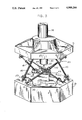
- FIG. 5 is a top view of the machine tool of FIGS. 3 and 4 as viewed through the section of the plane 5--5 of FIG. 4;
- FIG. 6 is a view in elevation of a third embodiment of a machine tool in accordance with the invention.
- FIG. 7 is a partial view in elevation of a leg and instrument arm arrangement usable with any of the embodiments.
- FIG. 8 is a schematic view of a control for a machine tool in accordance with the invention.
- FIG. 9 is a schematic diagram of a second embodiment of a control.
- FIG. 10 is a schematic diagram of a third embodiment of a control.
- the machine tool of the first embodiment has a base 10 in the nature of a support or platform and a spindle support or platform 11 spaced from the base 10.
- a spindle head 12 is mounted on the spindle platform 11 and is adapted to receive a rotating cutting tool 13.
- a spindle drive assembly indicated generally by the numeral 14 is mounted on the spindle platform 11 and the drive includes a motor 15 connected by a power train to the spindle head 12 in a usual manner.
- the base platform 10 carries a workpiece support 16 which in turn receives a workpiece represented by the part 17.
- the spaced platforms 10 and 11 are joined together by six powered and extensible legs 20-25.
- Each of the legs is pivotally mounted at its lower extremity to the base platform 10 by a ball and socket joint 26.
- each of the upper ends of the legs 20-25 is pivotally attached to the spindle platform 11 by a second ball and socket joint 27.
- the legs 20-25 may be formed of telescoping upper and lower parts 20a and 20b, for example.
- the telescoping parts may be the piston rod 20a and cylinder 20b of a hydraulic cylinder.
- the length of such legs can be adjusted by increasing or decreasing the volume of hydraulic fluid in each cylinder.
- the position of the spindle support 11 relative to the base support 10 and therefore the position of the cutting tool 13 relative to the workpiece 17 can be adjusted by simultaneously manipulating the length of each of the six legs 20-25.
- the cutting tool 13 can be applied against all five exposed surfaces of a cubic type workpiece.
- the only constraints to the envelope of motion relative to the five exposed surfaces are the spread of the joints 26 on the base support 10 and the spread of the second joints 27 on the spindle support 11, the minimum and maximum length of the legs 20-25, the total range of linear motion of each of the legs, and the need to avoid placing certain legs in a common plane for purposes of stability.
- this construction allows the machining of contours in three dimensions as well as straight line point-to-point machining.
- the simultaneous manipulation of the length of each of the legs 20-25 can achieve motion in all six axes. That is, motion in a linear direction along each of the three orthogonal axes and rotary motion about each of those three axes.
- the six legs may be considered to be arranged in three pairs. That is, the legs 20 and 21 constitute a pair, the legs 22 and 23 constitute a second pair, and the legs 24 and 25 constitute a third pair. It should be noted that the legs of each pair are arranged so that they are at an angle with respect to each other.
- the joints 26 of the pair of legs 20 and 21 are close to each other.
- the joints 27 of adjacent legs 20 and 25, for example, are also close to each other.
- the effect is that the lower joints 26 generally define a triangle and the upper joints 27 also generally define a triangle. These two triangles and the six legs generally define edges of an octahedron. As shown in FIGS.
- the area of the base platform 10 circumscribed by the lower ball joints 26 and the are of the spindle support 11 circumscribed by the upper ball joints 27 are substantially the same. This is advantageous for several reasons. First, such as arrangement maximizes the structural stiffness of the machine. Secondly, the footprint of the machine is minimized for a particular cubic size of workpiece to be handled. Also, a greater envelope of surface area for the workpiece can be accommodated before certain legs and supports are positioned in a common plane thereby creating a potentially ambiguous position.
- the second embodiment includes a base support or platform 30, a spindle support 31 which mounts a spindle 32 adapted to receive a cutting tool 33.
- the spindle head is rotated by a spindle drive 34.
- the base support 30 and spindle support 31 are connected by six extensible legs 40-45.
- the legs are arranged in three pairs such as the pair 40 and 41 and legs of each pair cross each other so that they are again mounted at an angle with respect to each other.
- the legs 40-45 are also formed of telescoping upper and lower elements 40a and 40b, for example.
- the legs 40-45 are joined to the base support 30 at a first point near their lower end by a joint indicated generally by the numeral 50.
- the joint 50 includes a clevis 51 mounted for rotation about the axis of a shaft 52 that projects from the base support 30.
- a typical trunnion 53 engages the lower element 40b-45b of each leg and is rotatably mounted in a clevis 51. It will thus be seen that a joint 50 provides two degrees of freedom of movement.
- the upper telescoping portions 40a-45a of the legs are similarly joined to the spindle support 31 at second points along the length of the legs by joints 54.
- the joints 54 likewise consist of a clevis 55 rotatably mounted on a shaft 56 extending downwardly from the underside of the spindle support 31 and a trunnion 57 which supports the upper leg portions 40a et seq. in the clevis 55.
- the joints 50 and 54 and their attachments to the supports 30 and 31 define the corners of a six-sided polygon in each of the two supports.
- the area of the base support 30 that is circumscribed by the connections of six lower joints 50 with the base support 30 is substantially the same as the area of the spindle support 31 that is circumscribed by the connections of the six upper joints 54 with the spindle support 31.
- the shafts 52 and 56 of the joints 50 and 54 can be mounted in their respective supports to project in any direction.
- the ball joints of the first embodiment could also be used in this second embodiment, and the trunnion joints of this second embodiment could be used in the first.
- the base support 30 mounts a workpiece support 58 which holds a workpiece exemplified by the part 59.
- the legs 40-45 may also be formed as hydraulic cylinders with the piston rod defining the upper end 40a et seq. and the cylinder portion forming the lower ends 40b et. seq. Because the piston rod can rotate within the cylinder, the two degrees of motion afforded at each of the joints 50 and 54 are sufficient. If the upper and lower portions of the actuators forming the legs cannot be allowed to twist, an actuator other than a hydraulic cylinder is used to accomplish the extension, and a third degree of rotational motion will be required in one or the other of the upper and lower joints 50 and 54.
- any means for achieving linear motion can be used such as forming the upper portion of each leg as a lead screw and mounting a rotating nut in the lower portion of the leg or vice versa.
- Alternatives are linear motors, recirculating ball screw drives, chain drives, and so forth.
- neither the tool nor the workpiece is located within the envelope defined by the leg structure.
- the workpiece 60 is mounted on a workpiece support 61 which in turn is mounted on a base 62 that is attached to an upright 63.
- the six legs 64-69 are connected at one end to the upright 63 by trunnion joints 70 in a manner similar to that of the second embodiment.
- the opposite ends of the legs 64-69 are connected by trunnion joints 71 to the spindle support 72.
- the spindle support carries a spindle 73 adapted to mount a tool 74 and the spindle 73 is driven by a spindle drive 75.
- the tool 74 projects away from the envelope defined by the legs 64-69.
- the third embodiment is otherwise the same as the first embodiment.
- the workpiece support 61 may be mounted on ways supported by the base 62 so that the workpiece support 61 with the workpiece 60 may move relative to the tool 74. Even though the workpiece 60 is not mounted on the upright 63, the workpiece location relative to the upright support 63 can be fixed, or at least known, at any instant in time.
- spindle and workpiece can also be employed, such as mounting the workpiece above the spindle or mounting an upright 63 as in the third embodiment on ways so that it can travel along the length of a workpiece.
- the legs must be moved in a coordinated manner in order to position the supports or platforms relative to each other.
- the coordinated movement is preferably accomplished by a computer control which provides a position signal for each leg to achieve a desired position for the spindle platform relative to the base platform and therefore for the cutting tool relative to the workpiece.
- a computer control which provides a position signal for each leg to achieve a desired position for the spindle platform relative to the base platform and therefore for the cutting tool relative to the workpiece.
- FIGS. 8 and 9 Suitable control schemes are illustrated in FIGS. 8 and 9.
- the leg in the form of a hydraulic cylinder such as the legs 20-25 are controlled by a servo valve 100 which controls the volume of hydraulic fluid in the cylinder and therefore the position of the piston rod within the cylinder.
- a computer 101 produces an output position command in the line 102.
- That position command is compared in a summing circuit 103 with a feedback position signal in a line 104 leading from an exciter/demodulator 105 that receives the signal from a sensing head 106 traveling along a magnetic scale 107.
- the sensing head 106 is coupled to the piston rod 20a et seq. so that changes in position of the piston rod will be reflected in changes in position of the sensing head 106 along the magnetic scale 107 which is at a known position, either fixed or varying, with respect to the hydraulic cylinder 20b et seq.
- the summing circuit 103 produces a position error signal in a line 108 which inputs to an integration network 109, the output of which is a velocity command in a line 110.
- the velocity command is compared with a velocity feedback signal in a line 111 leading from the exciter/demodulator 105 and the two signals are fed to a summing circuit 112 which produces an output signal representative of a velocity error.
- This velocity error signal is fed to a compensation network 113 where phase shift compensation takes place, and the resulting compensated signal is fed to an amplifier 114 which in turns controls the servo valve 100.
- a similar control loop leading from the computer would be provided for each of the six legs 20-25 and the computer 101 would generate an output position command for the desired position of each of the six legs to achieve a particular finite position of the cutting tool relative to the workpiece.
- FIG. 9 The control arrangement of FIG. 9 is similar to that of FIG. 8 but is shown in relation to a motor 120 rotating a lead screw and nut arrangement.
- An encoder or resolver 121 is connected to the motor 120 to provide a position feedback signal through the exciter/demodulator 122, and that position signal is compared at a summing junction 123 with the position command from the computer 61 to produce a position error signal fed to the integration network 124 which outputs a velocity command compared at a summing junction 125 with the velocity position signal from a tachometer 126 connected to the motor 120.
- a compensation network 127 functions to produce an appropriate signal to an amplifier 128 connected to the motor drive.
- the control scheme of FIG. 9 employs closed loop control. However, by using a stepping motor it is not necessary to have a closed loop control.
- An example of a control system using a stepping motor is shown in FIG. 10.
- Position signals can be provided by sensors that are directly connected to each of the legs or to the actuators for the legs. However, a more accurate approach uses separate instrument arms. Such an arrangement is shown in FIG. 7.
- a six legged machine tool of the embodiment shown in FIGS. 3-6 has separate instrument arms 130 and 131 associated with respective powered legs 44 and 45, respectively.
- the instrument arms 130 and 131 are each linearly extensible and are connected at their lower ends to the base platform 30 by trunnion joints 132 and at their upper ends to the spindle platform 31 by trunnion joints 133.
- the trunnion joints 132 and 133 are the same in structure and operation as the joints 50 and 54 used to connect power legs 44 and 45 to the platforms 30 and 31.
- the instrument arms 130 and 131 are used solely for the purpose of sensing the relative positions of the platforms.
- the instrument arms can include a sensing head traveling along a magnetic scale to provide the desired feedback signal as to length and therefore as to position. Other forms of instrument arms can also be used.
- the advantage in using the separate instrument arms is that the load deflections that will occur in the power legs and their joints will not be translated into errors in the position of the cutting tool.
- the instrument arms being smaller and lighter and carrying no weight other than their own, are not subject to the same forces and deflections to which the powered legs are subject.
- instrument arms 130 and 131 are shown mounted parallel with respective power legs, it is not necessary for the instrument arms to be so mounted. Instrument arms are not required to be associated with any particular power leg. It is, however, necessary to have at least six instrument arms to provide an unambiguous set of signals for the positions of the supports or platforms relative to each other.
Landscapes
- Engineering & Computer Science (AREA)
- Mechanical Engineering (AREA)
- Human Computer Interaction (AREA)
- Manufacturing & Machinery (AREA)
- Physics & Mathematics (AREA)
- General Physics & Mathematics (AREA)
- Automation & Control Theory (AREA)
- Robotics (AREA)
- Health & Medical Sciences (AREA)
- General Health & Medical Sciences (AREA)
- Orthopedic Medicine & Surgery (AREA)
- Machine Tool Units (AREA)
Abstract
Description
Claims (5)
Priority Applications (1)
| Application Number | Priority Date | Filing Date | Title |
|---|---|---|---|
| US07/572,167 US4988244A (en) | 1989-09-01 | 1990-08-23 | Six-axis machine tool |
Applications Claiming Priority (2)
| Application Number | Priority Date | Filing Date | Title |
|---|---|---|---|
| US07/401,909 US5028180A (en) | 1989-09-01 | 1989-09-01 | Six-axis machine tool |
| US07/572,167 US4988244A (en) | 1989-09-01 | 1990-08-23 | Six-axis machine tool |
Related Parent Applications (1)
| Application Number | Title | Priority Date | Filing Date |
|---|---|---|---|
| US07/401,909 Division US5028180A (en) | 1989-09-01 | 1989-09-01 | Six-axis machine tool |
Publications (1)
| Publication Number | Publication Date |
|---|---|
| US4988244A true US4988244A (en) | 1991-01-29 |
Family
ID=27017639
Family Applications (1)
| Application Number | Title | Priority Date | Filing Date |
|---|---|---|---|
| US07/572,167 Expired - Fee Related US4988244A (en) | 1989-09-01 | 1990-08-23 | Six-axis machine tool |
Country Status (1)
| Country | Link |
|---|---|
| US (1) | US4988244A (en) |
Cited By (75)
| Publication number | Priority date | Publication date | Assignee | Title |
|---|---|---|---|---|
| US5109592A (en) * | 1989-09-11 | 1992-05-05 | Jobs S.P.A. | Machine tool |
| US5259710A (en) * | 1991-08-26 | 1993-11-09 | Ingersoll Milling Machine Company | Octahedral machine tool frame |
| US5263382A (en) * | 1992-04-13 | 1993-11-23 | Hughes Aircraft Company | Six Degrees of freedom motion device |
| US5305981A (en) * | 1991-10-31 | 1994-04-26 | Honeywell Inc. | Multiaxis vibration isolation system |
| EP0589565A3 (en) * | 1992-09-18 | 1994-06-01 | Ingersoll Milling Machine Co | Octahedral machine with a hexapodal triangular servostrut section |
| US5348124A (en) * | 1989-03-16 | 1994-09-20 | Active Noise And Vibration Technologies, Inc. | Active control of vibration |
| US5388935A (en) * | 1993-08-03 | 1995-02-14 | Giddings & Lewis, Inc. | Six axis machine tool |
| US5466085A (en) * | 1989-09-01 | 1995-11-14 | Giddings & Lewis, Inc. | Gimbal assembly for six axis machine tool |
| US5538373A (en) * | 1992-02-20 | 1996-07-23 | Giddings & Lewis, Inc. | Machine tool vibration isolation system |
| US5556242A (en) * | 1994-06-17 | 1996-09-17 | Giddings & Lewis, Inc. | Space frame for a machine tool |
| US5575597A (en) * | 1991-04-05 | 1996-11-19 | Geodetic Technology International Holdings N.V. | Mechanical manipulator |
| WO1996036462A1 (en) * | 1995-05-19 | 1996-11-21 | Mcgill University | Deformable structural arrangement |
| EP0760272A1 (en) * | 1995-07-31 | 1997-03-05 | Hihaisuto Seiko Co Ltd | A multi-degree-of-freedom positioning mechanism |
| US5617964A (en) * | 1992-06-13 | 1997-04-08 | Krupp Fordertechnik Gmbh | Lifting means for loads |
| WO1997025180A3 (en) * | 1996-01-03 | 1997-08-14 | Uwe Heisel | Device with at least one movement unit |
| US5681981A (en) * | 1994-01-28 | 1997-10-28 | Renishaw Plc | Performing measurement or calibration on positioning machines |
| US5702389A (en) * | 1995-03-01 | 1997-12-30 | Smith & Nephew Richards, Inc. | Orthopaedic fixation device |
| US5715729A (en) * | 1994-11-29 | 1998-02-10 | Toyoda Koki Kabushiki Kaisha | Machine tool having parallel structure |
| US5727391A (en) * | 1995-10-16 | 1998-03-17 | Mcgill University | Deformable structural arrangement |
| US5728095A (en) * | 1995-03-01 | 1998-03-17 | Smith & Nephew, Inc. | Method of using an orthopaedic fixation device |
| WO1998034048A3 (en) * | 1997-02-03 | 1998-12-10 | Honeywell Inc | Load vibration isolation apparatus |
| US5901936A (en) * | 1997-08-25 | 1999-05-11 | Sandia Corporation | Six-degree-of-freedom multi-axes positioning apparatus |
| US5906461A (en) * | 1997-04-09 | 1999-05-25 | Ina Walzlager Schaeffler Ohg | Machine tool with adjustable strut assembly |
| US5940180A (en) * | 1994-10-11 | 1999-08-17 | Giddings & Lewis | Laser interferometer measurement system for use with machine tools |
| US5941128A (en) * | 1996-10-21 | 1999-08-24 | Toyoda Kokoi Kabushiki Kaisha | Machine tool having parallel structure |
| US5971984A (en) * | 1995-03-01 | 1999-10-26 | Smith & Nephew, Inc. | Method of using an orthopaedic fixation device |
| US5987726A (en) * | 1996-03-11 | 1999-11-23 | Fanuc Robotics North America, Inc. | Programmable positioner for the stress-free assembly of components |
| US6041500A (en) * | 1998-01-23 | 2000-03-28 | Giddings & Lewis, Inc. | Automatic assembly machine and method utilizing six-axis positioning device |
| US6048143A (en) * | 1999-01-30 | 2000-04-11 | Industrial Technology Research Institute | Composite mechanism multi-axis machine tool |
| US6047610A (en) * | 1997-04-18 | 2000-04-11 | Stocco; Leo J | Hybrid serial/parallel manipulator |
| US6099217A (en) * | 1995-12-20 | 2000-08-08 | Wiegand; Alexander Konrad | Device for spatially moving a body with three to six degrees of freedom in a controlled manner |
| US6203254B1 (en) * | 1998-10-19 | 2001-03-20 | Okuma Corporation | Parallel mechanism machining device |
| US6228007B1 (en) | 1999-05-05 | 2001-05-08 | Honsberg Lamb Sonderwerkzeugmaschinen Gmbh | Machine tool for processing crankshafts |
| US6240799B1 (en) * | 1998-05-26 | 2001-06-05 | Hexel Corporation | Triangular gimbal |
| US6272766B1 (en) | 1997-10-27 | 2001-08-14 | Johannes Heidenhain Gmbh | Length measuring instrument, and machine having a length measuring instrument |
| FR2822525A1 (en) * | 2001-03-21 | 2002-09-27 | Sagem | Support for fixing and adjusting a component such as a precision optical instrument has base with triangular levers and regulators |
| US6587265B1 (en) * | 1999-11-25 | 2003-07-01 | Mitsubishi Denki Kabushiki Kaisha | Prime focus unit |
| US20030204965A1 (en) * | 2001-12-10 | 2003-11-06 | Hennessey C. William | Parallel kinematic micromanipulator |
| US20040067117A1 (en) * | 2000-12-08 | 2004-04-08 | Claude Fioroni | Machine-tool in particular with parallel architecture accommodating deformed articulations |
| US20060228182A1 (en) * | 2003-07-01 | 2006-10-12 | Franco Pasquetto | Numeric/control machine |
| US20070000888A1 (en) * | 2004-11-29 | 2007-01-04 | Tsunehiko Yamazaki | Laser processing machine |
| USRE40914E1 (en) | 1997-10-20 | 2009-09-08 | Smith & Nephew, Inc. | Orthopaedic fixation plate |
| US20100078866A1 (en) * | 2006-12-21 | 2010-04-01 | Hexagon Metrology Ab | Method and device for the compensation of geometrical errors in machining machinery |
| US20100087819A1 (en) * | 2008-10-07 | 2010-04-08 | Extraortho, Inc. | Forward Kinematic Solution for a Hexapod Manipulator and Method of Use |
| US20100122602A1 (en) * | 2008-11-17 | 2010-05-20 | Marcroft Sacha L | Parallel kinematic positioning system |
| US20100305568A1 (en) * | 2008-02-05 | 2010-12-02 | Texas Scottish Rite Hospital For Children | External fixator ring |
| US20110004199A1 (en) * | 2008-02-18 | 2011-01-06 | Texas Scottish Rite Hospital For Children | Tool and method for external fixation strut adjustment |
| US20110061310A1 (en) * | 2007-06-05 | 2011-03-17 | Gm Global Technology Operations, Inc. | Tunable impedance load-bearing structures |
| US20110118738A1 (en) * | 2009-11-13 | 2011-05-19 | Amei Technologies, Inc. | Adjustable orthopedic fixation system |
| US20110118737A1 (en) * | 2009-11-13 | 2011-05-19 | Amei Technologies, Inc. | Fixation device and multiple-axis joint for a fixation device |
| US20110290061A1 (en) * | 2010-05-25 | 2011-12-01 | Raju G Jagannath | Hybrid serial-parallel linkage based six degrees of freedom robotic manipulator |
| US20120216350A1 (en) * | 2011-02-10 | 2012-08-30 | Maquet Gmbh & Co. Kg | Operating table column |
| US20130074316A1 (en) * | 2008-06-20 | 2013-03-28 | Robert Bosch Gmbh | Method of Making a Base of a Miter Saw |
| JP2013529558A (en) * | 2010-06-28 | 2013-07-22 | シュヴァブ・マーチン | Hexapod |
| CN103231364A (en) * | 2013-05-07 | 2013-08-07 | 林发明 | Three-freedom-degree and four-freedom-degree parallel mechanism |
| CN103274064A (en) * | 2013-05-09 | 2013-09-04 | 燕山大学 | Folding type six-freedom-degree parallel connection posture adjusting platform |
| CN103317498A (en) * | 2013-05-31 | 2013-09-25 | 燕山大学 | Folding type five-degree-of-freedom parallel connected attitude adjustment platform |
| US8574232B1 (en) | 2012-11-13 | 2013-11-05 | Texas Scottish Hospital for Children | External fixation connection rod for rapid and gradual adjustment |
| CN103465255A (en) * | 2013-09-24 | 2013-12-25 | 北京交通大学 | Hydraulic drive parallel moving robot |
| US20140263883A1 (en) * | 2013-03-18 | 2014-09-18 | Rolls-Royce Plc | Machine tool |
| US9078700B2 (en) | 2008-02-12 | 2015-07-14 | Texas Scottish Rite Hospital For Children | Fast adjust external fixation connection rod |
| US9155559B2 (en) | 2008-02-08 | 2015-10-13 | Texas Scottish Rite Hospital For Children | External fixator strut |
| CN104976488A (en) * | 2015-07-22 | 2015-10-14 | 湖南科技大学 | Three-freedom-degree active vibration isolation platform |
| US9186180B2 (en) | 2013-03-08 | 2015-11-17 | Stryker Trauma Sa | Rose gear for external fixation clamp |
| JP2015210245A (en) * | 2014-04-30 | 2015-11-24 | 平田機工株式会社 | Work-piece shape measurement system and control method |
| US9443302B2 (en) | 2010-08-20 | 2016-09-13 | Amei Technologies, Inc. | Method and system for roentgenography-based modeling |
| CN106625610A (en) * | 2017-02-23 | 2017-05-10 | 哈尔滨工业大学 | Side-standing crossed-rod parallel-mechanism six-degree-of-freedom spacecraft motion simulation platform |
| DE202014011139U1 (en) | 2013-12-06 | 2018-01-29 | Huber Diffraktionstechnik Gmbh & Co. Kg | Redunante parallel positioning table device |
| US20180209788A1 (en) * | 2015-08-05 | 2018-07-26 | Renishaw Plc | Coordinate positioning machine |
| CN109015602A (en) * | 2018-08-29 | 2018-12-18 | 燕山大学 | Three translation 2CPR-URU parallel institutions |
| EP3336381A4 (en) * | 2015-08-10 | 2019-04-17 | NTN Corporation | WORKING MACHINE WITH PARALLEL LINK MECHANISM |
| EP3782769A1 (en) | 2019-08-20 | 2021-02-24 | Huber Diffraktionstechnik GmbH & Co. KG | Redundant parallel positioning table device |
| US10967502B2 (en) | 2017-10-13 | 2021-04-06 | Renishaw Plc | Coordinate positioning machine |
| WO2021170604A1 (en) * | 2020-02-24 | 2021-09-02 | Physik Instrumente (Pi) Gmbh & Co. Kg | Compact 6-axis positioning system |
| US11624603B2 (en) | 2019-04-12 | 2023-04-11 | Renishaw Plc | Coordinate positioning machine |
Citations (9)
| Publication number | Priority date | Publication date | Assignee | Title |
|---|---|---|---|---|
| GB2083795A (en) * | 1980-09-13 | 1982-03-31 | Marconi Co Ltd | Manipulator mechanisms |
| SU1049244A1 (en) * | 1982-02-11 | 1983-10-23 | Belikov Viktor T | Manipulator |
| SU1194672A1 (en) * | 1983-11-23 | 1985-11-30 | Институт Машиноведения Им.А.А.Благонравова | Three-dimensional mechanism |
| SU1222538A1 (en) * | 1984-06-15 | 1986-04-07 | Институт Машиноведения Им.А.А.Благонравова | Coordinate spatial mechanism (versions) |
| GB2179605A (en) * | 1985-08-27 | 1987-03-11 | Singer Link Miles Ltd | Motion simulator |
| SU1296401A1 (en) * | 1985-01-07 | 1987-03-15 | Новосибирский электротехнический институт | Machining device |
| US4651589A (en) * | 1983-03-08 | 1987-03-24 | Societe Bauduin Becart S.A. | Polyarticulated retractile mechanism |
| US4806068A (en) * | 1986-09-30 | 1989-02-21 | Dilip Kohli | Rotary linear actuator for use in robotic manipulators |
| US4819496A (en) * | 1987-11-17 | 1989-04-11 | The United States Of America As Represented By The Secretary Of The Air Force | Six degrees of freedom micromanipulator |
-
1990
- 1990-08-23 US US07/572,167 patent/US4988244A/en not_active Expired - Fee Related
Patent Citations (9)
| Publication number | Priority date | Publication date | Assignee | Title |
|---|---|---|---|---|
| GB2083795A (en) * | 1980-09-13 | 1982-03-31 | Marconi Co Ltd | Manipulator mechanisms |
| SU1049244A1 (en) * | 1982-02-11 | 1983-10-23 | Belikov Viktor T | Manipulator |
| US4651589A (en) * | 1983-03-08 | 1987-03-24 | Societe Bauduin Becart S.A. | Polyarticulated retractile mechanism |
| SU1194672A1 (en) * | 1983-11-23 | 1985-11-30 | Институт Машиноведения Им.А.А.Благонравова | Three-dimensional mechanism |
| SU1222538A1 (en) * | 1984-06-15 | 1986-04-07 | Институт Машиноведения Им.А.А.Благонравова | Coordinate spatial mechanism (versions) |
| SU1296401A1 (en) * | 1985-01-07 | 1987-03-15 | Новосибирский электротехнический институт | Machining device |
| GB2179605A (en) * | 1985-08-27 | 1987-03-11 | Singer Link Miles Ltd | Motion simulator |
| US4806068A (en) * | 1986-09-30 | 1989-02-21 | Dilip Kohli | Rotary linear actuator for use in robotic manipulators |
| US4819496A (en) * | 1987-11-17 | 1989-04-11 | The United States Of America As Represented By The Secretary Of The Air Force | Six degrees of freedom micromanipulator |
Cited By (126)
| Publication number | Priority date | Publication date | Assignee | Title |
|---|---|---|---|---|
| US5348124A (en) * | 1989-03-16 | 1994-09-20 | Active Noise And Vibration Technologies, Inc. | Active control of vibration |
| US5466085A (en) * | 1989-09-01 | 1995-11-14 | Giddings & Lewis, Inc. | Gimbal assembly for six axis machine tool |
| US5489168A (en) * | 1989-09-01 | 1996-02-06 | Giddings & Lewis | Metrology instrument arm system |
| US5109592A (en) * | 1989-09-11 | 1992-05-05 | Jobs S.P.A. | Machine tool |
| US5857815A (en) * | 1991-04-05 | 1999-01-12 | Geodetic Technology International Holdings N.V. | Mechanical manipulator |
| US5575597A (en) * | 1991-04-05 | 1996-11-19 | Geodetic Technology International Holdings N.V. | Mechanical manipulator |
| US5401128A (en) * | 1991-08-26 | 1995-03-28 | Ingersoll Milling Machine Company | Octahedral machine with a hexapodal triangular servostrut section |
| US5392663A (en) * | 1991-08-26 | 1995-02-28 | The Ingersoll Milling Machine Company | Octahedral machine tool frame |
| US5259710A (en) * | 1991-08-26 | 1993-11-09 | Ingersoll Milling Machine Company | Octahedral machine tool frame |
| US5305981A (en) * | 1991-10-31 | 1994-04-26 | Honeywell Inc. | Multiaxis vibration isolation system |
| US5538373A (en) * | 1992-02-20 | 1996-07-23 | Giddings & Lewis, Inc. | Machine tool vibration isolation system |
| US5263382A (en) * | 1992-04-13 | 1993-11-23 | Hughes Aircraft Company | Six Degrees of freedom motion device |
| US5617964A (en) * | 1992-06-13 | 1997-04-08 | Krupp Fordertechnik Gmbh | Lifting means for loads |
| EP0589565A3 (en) * | 1992-09-18 | 1994-06-01 | Ingersoll Milling Machine Co | Octahedral machine with a hexapodal triangular servostrut section |
| US5388935A (en) * | 1993-08-03 | 1995-02-14 | Giddings & Lewis, Inc. | Six axis machine tool |
| US6918188B2 (en) | 1994-01-28 | 2005-07-19 | Renishaw Plc | Performing measurement or calibration on positioning machines |
| US20050241169A1 (en) * | 1994-01-28 | 2005-11-03 | Renishaw Plc | Performing measurement or calibration on positioning machines |
| US6226884B1 (en) | 1994-01-28 | 2001-05-08 | Renishaw Plc | Method for performing measurements on positioning machines using triangularly arrayed support structures and pre-calibrated extendible measuring bars |
| US5681981A (en) * | 1994-01-28 | 1997-10-28 | Renishaw Plc | Performing measurement or calibration on positioning machines |
| US20070151117A1 (en) * | 1994-01-28 | 2007-07-05 | Renishaw Plc | Performing measurement or calibration on positioning machines |
| US6662461B2 (en) | 1994-01-28 | 2003-12-16 | Renishaw Plc | Performing measurement or calibration on positioning machines |
| US7174652B2 (en) | 1994-01-28 | 2007-02-13 | Renishaw Plc | Performing measurement or calibration on positioning machines |
| US5556242A (en) * | 1994-06-17 | 1996-09-17 | Giddings & Lewis, Inc. | Space frame for a machine tool |
| US5940180A (en) * | 1994-10-11 | 1999-08-17 | Giddings & Lewis | Laser interferometer measurement system for use with machine tools |
| US5715729A (en) * | 1994-11-29 | 1998-02-10 | Toyoda Koki Kabushiki Kaisha | Machine tool having parallel structure |
| US5971984A (en) * | 1995-03-01 | 1999-10-26 | Smith & Nephew, Inc. | Method of using an orthopaedic fixation device |
| US5728095A (en) * | 1995-03-01 | 1998-03-17 | Smith & Nephew, Inc. | Method of using an orthopaedic fixation device |
| US5702389A (en) * | 1995-03-01 | 1997-12-30 | Smith & Nephew Richards, Inc. | Orthopaedic fixation device |
| WO1996036462A1 (en) * | 1995-05-19 | 1996-11-21 | Mcgill University | Deformable structural arrangement |
| EP0760272A1 (en) * | 1995-07-31 | 1997-03-05 | Hihaisuto Seiko Co Ltd | A multi-degree-of-freedom positioning mechanism |
| US5727391A (en) * | 1995-10-16 | 1998-03-17 | Mcgill University | Deformable structural arrangement |
| US6099217A (en) * | 1995-12-20 | 2000-08-08 | Wiegand; Alexander Konrad | Device for spatially moving a body with three to six degrees of freedom in a controlled manner |
| US6059703A (en) * | 1996-01-03 | 2000-05-09 | Heisel; Uwe | Device with at least one movement unit |
| WO1997025180A3 (en) * | 1996-01-03 | 1997-08-14 | Uwe Heisel | Device with at least one movement unit |
| US5987726A (en) * | 1996-03-11 | 1999-11-23 | Fanuc Robotics North America, Inc. | Programmable positioner for the stress-free assembly of components |
| US6425177B1 (en) | 1996-03-11 | 2002-07-30 | Fanuc Robotics North America, Inc. | Programmable positioner for the stress-free assembly of assemblies |
| US6378190B2 (en) | 1996-03-11 | 2002-04-30 | Fanuc Robotics North America, Inc. | Method for stress-free assembly of components |
| US5941128A (en) * | 1996-10-21 | 1999-08-24 | Toyoda Kokoi Kabushiki Kaisha | Machine tool having parallel structure |
| US5947240A (en) * | 1997-02-03 | 1999-09-07 | Honeywell, Inc. | Load vibration isolation apparatus |
| WO1998034048A3 (en) * | 1997-02-03 | 1998-12-10 | Honeywell Inc | Load vibration isolation apparatus |
| US5906461A (en) * | 1997-04-09 | 1999-05-25 | Ina Walzlager Schaeffler Ohg | Machine tool with adjustable strut assembly |
| US6047610A (en) * | 1997-04-18 | 2000-04-11 | Stocco; Leo J | Hybrid serial/parallel manipulator |
| US5901936A (en) * | 1997-08-25 | 1999-05-11 | Sandia Corporation | Six-degree-of-freedom multi-axes positioning apparatus |
| USRE40914E1 (en) | 1997-10-20 | 2009-09-08 | Smith & Nephew, Inc. | Orthopaedic fixation plate |
| US6272766B1 (en) | 1997-10-27 | 2001-08-14 | Johannes Heidenhain Gmbh | Length measuring instrument, and machine having a length measuring instrument |
| US6041500A (en) * | 1998-01-23 | 2000-03-28 | Giddings & Lewis, Inc. | Automatic assembly machine and method utilizing six-axis positioning device |
| US6240799B1 (en) * | 1998-05-26 | 2001-06-05 | Hexel Corporation | Triangular gimbal |
| US6203254B1 (en) * | 1998-10-19 | 2001-03-20 | Okuma Corporation | Parallel mechanism machining device |
| US6048143A (en) * | 1999-01-30 | 2000-04-11 | Industrial Technology Research Institute | Composite mechanism multi-axis machine tool |
| US6228007B1 (en) | 1999-05-05 | 2001-05-08 | Honsberg Lamb Sonderwerkzeugmaschinen Gmbh | Machine tool for processing crankshafts |
| US6587265B1 (en) * | 1999-11-25 | 2003-07-01 | Mitsubishi Denki Kabushiki Kaisha | Prime focus unit |
| US6877938B2 (en) * | 2000-12-08 | 2005-04-12 | Renault Automation Comau | Machine-tool in particular with parallel architecture accommodating deformed articulations |
| US20040067117A1 (en) * | 2000-12-08 | 2004-04-08 | Claude Fioroni | Machine-tool in particular with parallel architecture accommodating deformed articulations |
| US20040105138A1 (en) * | 2001-03-21 | 2004-06-03 | Jacques Billet | Device for fixing and adjusting a member to be supported |
| US7063300B2 (en) | 2001-03-21 | 2006-06-20 | Sagem Sa | Device for fixing and adjusting a member to be supported |
| WO2002075365A3 (en) * | 2001-03-21 | 2003-04-03 | Sagem | Device for fixing and adjusting an element to be supported |
| FR2822525A1 (en) * | 2001-03-21 | 2002-09-27 | Sagem | Support for fixing and adjusting a component such as a precision optical instrument has base with triangular levers and regulators |
| US6769194B2 (en) | 2001-12-10 | 2004-08-03 | C. William Hennessey | Parallel kinematic micromanipulator |
| US6671975B2 (en) * | 2001-12-10 | 2004-01-06 | C. William Hennessey | Parallel kinematic micromanipulator |
| US20030204965A1 (en) * | 2001-12-10 | 2003-11-06 | Hennessey C. William | Parallel kinematic micromanipulator |
| US7261502B2 (en) * | 2003-07-01 | 2007-08-28 | O.M.V. Officine Meccaniche Venete S.R.L. | Numeric/control machine |
| US20060228182A1 (en) * | 2003-07-01 | 2006-10-12 | Franco Pasquetto | Numeric/control machine |
| US20070000888A1 (en) * | 2004-11-29 | 2007-01-04 | Tsunehiko Yamazaki | Laser processing machine |
| US7745756B2 (en) * | 2004-11-29 | 2010-06-29 | Yamazaki Mazak Corporation | Laser processing machine |
| US20100078866A1 (en) * | 2006-12-21 | 2010-04-01 | Hexagon Metrology Ab | Method and device for the compensation of geometrical errors in machining machinery |
| US20110061310A1 (en) * | 2007-06-05 | 2011-03-17 | Gm Global Technology Operations, Inc. | Tunable impedance load-bearing structures |
| US8448436B2 (en) * | 2007-06-05 | 2013-05-28 | GM Global Technology Operations LLC | Tunable impedance load-bearing structures |
| US20120161921A1 (en) * | 2007-06-05 | 2012-06-28 | GM Global Technology Operations LLC | Tunable impedance load-bearing structures |
| US8205445B2 (en) * | 2007-06-05 | 2012-06-26 | GM Global Technology Operations LLC | Tunable impedance load-bearing structures |
| US9295493B2 (en) | 2008-02-05 | 2016-03-29 | Texas Scottish Rite Hospital For Children | External fixator ring |
| US9808289B2 (en) | 2008-02-05 | 2017-11-07 | Texas Scottish Rite Hospital For Children | External fixator ring |
| US20100305568A1 (en) * | 2008-02-05 | 2010-12-02 | Texas Scottish Rite Hospital For Children | External fixator ring |
| US9681892B2 (en) | 2008-02-08 | 2017-06-20 | Texas Scottish Rite Hospital For Children | External fixator strut |
| US9155559B2 (en) | 2008-02-08 | 2015-10-13 | Texas Scottish Rite Hospital For Children | External fixator strut |
| US9456849B2 (en) | 2008-02-12 | 2016-10-04 | Texas Scottish Rite Hospital For Children | Fast adjust external fixation connection rod |
| US9078700B2 (en) | 2008-02-12 | 2015-07-14 | Texas Scottish Rite Hospital For Children | Fast adjust external fixation connection rod |
| US20110004199A1 (en) * | 2008-02-18 | 2011-01-06 | Texas Scottish Rite Hospital For Children | Tool and method for external fixation strut adjustment |
| US8864750B2 (en) | 2008-02-18 | 2014-10-21 | Texas Scottish Rite Hospital For Children | Tool and method for external fixation strut adjustment |
| US20130074316A1 (en) * | 2008-06-20 | 2013-03-28 | Robert Bosch Gmbh | Method of Making a Base of a Miter Saw |
| US20100087819A1 (en) * | 2008-10-07 | 2010-04-08 | Extraortho, Inc. | Forward Kinematic Solution for a Hexapod Manipulator and Method of Use |
| US8215199B2 (en) * | 2008-11-17 | 2012-07-10 | Marcroft Sacha L | Parallel kinematic positioning system |
| US20100122602A1 (en) * | 2008-11-17 | 2010-05-20 | Marcroft Sacha L | Parallel kinematic positioning system |
| US8377060B2 (en) | 2009-11-13 | 2013-02-19 | Amei Technologies, Inc. | Fixation device and multiple-axis joint for a fixation device |
| US8425512B2 (en) | 2009-11-13 | 2013-04-23 | Amei Technologies, Inc. | Fixation device and multiple-axis joint for a fixation device |
| US8430878B2 (en) * | 2009-11-13 | 2013-04-30 | Amei Technologies, Inc. | Adjustable orthopedic fixation system |
| US20110118737A1 (en) * | 2009-11-13 | 2011-05-19 | Amei Technologies, Inc. | Fixation device and multiple-axis joint for a fixation device |
| US20110118738A1 (en) * | 2009-11-13 | 2011-05-19 | Amei Technologies, Inc. | Adjustable orthopedic fixation system |
| US20110290061A1 (en) * | 2010-05-25 | 2011-12-01 | Raju G Jagannath | Hybrid serial-parallel linkage based six degrees of freedom robotic manipulator |
| US8601899B2 (en) * | 2010-05-25 | 2013-12-10 | Systemantics India Pvt. Ltd. | Hybrid serial-parallel linkage based six degrees of freedom robotic manipulator |
| US9109743B2 (en) | 2010-06-28 | 2015-08-18 | Martin Schwab | Hexapod |
| JP2013529558A (en) * | 2010-06-28 | 2013-07-22 | シュヴァブ・マーチン | Hexapod |
| US9443302B2 (en) | 2010-08-20 | 2016-09-13 | Amei Technologies, Inc. | Method and system for roentgenography-based modeling |
| US8800983B2 (en) * | 2011-02-10 | 2014-08-12 | MAQUET GmbH | Operating table column |
| US20120216350A1 (en) * | 2011-02-10 | 2012-08-30 | Maquet Gmbh & Co. Kg | Operating table column |
| US8574232B1 (en) | 2012-11-13 | 2013-11-05 | Texas Scottish Hospital for Children | External fixation connection rod for rapid and gradual adjustment |
| US9381042B2 (en) | 2012-11-13 | 2016-07-05 | Texas Scottish Rite Hospital For Children | External fixation connection rod for rapid and gradual adjustment |
| US9186180B2 (en) | 2013-03-08 | 2015-11-17 | Stryker Trauma Sa | Rose gear for external fixation clamp |
| US10221992B2 (en) * | 2013-03-18 | 2019-03-05 | Rolls-Royce Plc | Independently moveable machine tool |
| US20140263883A1 (en) * | 2013-03-18 | 2014-09-18 | Rolls-Royce Plc | Machine tool |
| CN103231364A (en) * | 2013-05-07 | 2013-08-07 | 林发明 | Three-freedom-degree and four-freedom-degree parallel mechanism |
| CN103274064A (en) * | 2013-05-09 | 2013-09-04 | 燕山大学 | Folding type six-freedom-degree parallel connection posture adjusting platform |
| CN103274064B (en) * | 2013-05-09 | 2015-09-16 | 燕山大学 | A kind of collapsible six-freedom parallel posture adjustment platform |
| CN103317498A (en) * | 2013-05-31 | 2013-09-25 | 燕山大学 | Folding type five-degree-of-freedom parallel connected attitude adjustment platform |
| CN103465255B (en) * | 2013-09-24 | 2015-08-26 | 北京交通大学 | A kind of hydraulic drive parallel mobile robot |
| CN103465255A (en) * | 2013-09-24 | 2013-12-25 | 北京交通大学 | Hydraulic drive parallel moving robot |
| DE202014011139U1 (en) | 2013-12-06 | 2018-01-29 | Huber Diffraktionstechnik Gmbh & Co. Kg | Redunante parallel positioning table device |
| JP2015210245A (en) * | 2014-04-30 | 2015-11-24 | 平田機工株式会社 | Work-piece shape measurement system and control method |
| CN104976488A (en) * | 2015-07-22 | 2015-10-14 | 湖南科技大学 | Three-freedom-degree active vibration isolation platform |
| CN104976488B (en) * | 2015-07-22 | 2016-12-21 | 湖南科技大学 | A kind of Three Degree Of Freedom Active Vibration Isolation Platform |
| US10816335B2 (en) * | 2015-08-05 | 2020-10-27 | Renishaw Plc | Coordinate positioning machine |
| US11300408B2 (en) | 2015-08-05 | 2022-04-12 | Renishaw Plc | Coordinate positioning machine |
| US20180209788A1 (en) * | 2015-08-05 | 2018-07-26 | Renishaw Plc | Coordinate positioning machine |
| EP3336381A4 (en) * | 2015-08-10 | 2019-04-17 | NTN Corporation | WORKING MACHINE WITH PARALLEL LINK MECHANISM |
| US10556308B2 (en) | 2015-08-10 | 2020-02-11 | Ntn Corporation | Work machine provided with parallel link mechanism |
| CN106625610B (en) * | 2017-02-23 | 2019-04-02 | 哈尔滨工业大学 | Side-vertical cross-bar parallel mechanism 6-DOF spacecraft motion simulation platform |
| CN106625610A (en) * | 2017-02-23 | 2017-05-10 | 哈尔滨工业大学 | Side-standing crossed-rod parallel-mechanism six-degree-of-freedom spacecraft motion simulation platform |
| US10967502B2 (en) | 2017-10-13 | 2021-04-06 | Renishaw Plc | Coordinate positioning machine |
| US11673256B2 (en) | 2017-10-13 | 2023-06-13 | Renishaw Plc | Coordinate positioning machine |
| CN109015602A (en) * | 2018-08-29 | 2018-12-18 | 燕山大学 | Three translation 2CPR-URU parallel institutions |
| US11624603B2 (en) | 2019-04-12 | 2023-04-11 | Renishaw Plc | Coordinate positioning machine |
| EP3782770A1 (en) | 2019-08-20 | 2021-02-24 | Huber Diffraktionstechnik GmbH & Co. KG | Redundant parallel positioning table device |
| EP3782769A1 (en) | 2019-08-20 | 2021-02-24 | Huber Diffraktionstechnik GmbH & Co. KG | Redundant parallel positioning table device |
| WO2021170604A1 (en) * | 2020-02-24 | 2021-09-02 | Physik Instrumente (Pi) Gmbh & Co. Kg | Compact 6-axis positioning system |
| CN115151391A (en) * | 2020-02-24 | 2022-10-04 | 物理仪器(Pi)两合有限公司 | Compact 6-axis positioning system |
| US12134185B2 (en) | 2020-02-24 | 2024-11-05 | Physik Instrumente (Pi) Gmbh & Co. Kg | Compact 6-axis positioning system |
| CN115151391B (en) * | 2020-02-24 | 2025-07-15 | 物理仪器(Pi)欧洲股份两合公司 | Compact 6-axis positioning system |
Similar Documents
| Publication | Publication Date | Title |
|---|---|---|
| US4988244A (en) | Six-axis machine tool | |
| US5028180A (en) | Six-axis machine tool | |
| US5538373A (en) | Machine tool vibration isolation system | |
| US5940180A (en) | Laser interferometer measurement system for use with machine tools | |
| US6336375B1 (en) | Coordinate positioning machine | |
| US5604593A (en) | Interferometer position measurement system with extensible legs | |
| US6662461B2 (en) | Performing measurement or calibration on positioning machines | |
| US5388935A (en) | Six axis machine tool | |
| JP2766290B2 (en) | Welding robot | |
| JPH08168930A (en) | Solid frame for machine tool | |
| JPH07290334A (en) | Coordinate locating machine | |
| KR100441306B1 (en) | A production positioning system | |
| US4534694A (en) | Multi-articulate arm mechanism | |
| JPH10109285A (en) | Manipulator | |
| JPS6052277A (en) | Heavy object handling system controller |
Legal Events
| Date | Code | Title | Description |
|---|---|---|---|
| AS | Assignment |
Owner name: KEARNEY & TRECKER CORPORATION, WISCONSIN Free format text: ASSIGNMENT OF ASSIGNORS INTEREST.;ASSIGNORS:SHELDON, PAUL C.;KIRKHAM, EDWARD E.;REEL/FRAME:005417/0502 Effective date: 19900822 |
|
| FEPP | Fee payment procedure |
Free format text: PAYOR NUMBER ASSIGNED (ORIGINAL EVENT CODE: ASPN); ENTITY STATUS OF PATENT OWNER: LARGE ENTITY |
|
| AS | Assignment |
Owner name: CITICORP. USA, INC. Free format text: SECURITY INTEREST;ASSIGNOR:KEARNEY & TRECKER CORPORATION;REEL/FRAME:005900/0761 Effective date: 19911031 |
|
| FEPP | Fee payment procedure |
Free format text: PAYOR NUMBER ASSIGNED (ORIGINAL EVENT CODE: ASPN); ENTITY STATUS OF PATENT OWNER: LARGE ENTITY Free format text: PAYER NUMBER DE-ASSIGNED (ORIGINAL EVENT CODE: RMPN); ENTITY STATUS OF PATENT OWNER: LARGE ENTITY |
|
| FPAY | Fee payment |
Year of fee payment: 4 |
|
| FPAY | Fee payment |
Year of fee payment: 8 |
|
| REMI | Maintenance fee reminder mailed | ||
| AS | Assignment |
Owner name: KEARNEY & TRECKER CORPORATION, WISCONSIN Free format text: RELEASE BY SECURED PARTY;ASSIGNOR:CITICORP USA, INC.;REEL/FRAME:013949/0870 Effective date: 19921231 |
|
| AS | Assignment |
Owner name: GIDDINGS & LEWIS, LLC, WISCONSIN Free format text: MERGER;ASSIGNOR:KEARNEY & TRECKER CORPORATION;REEL/FRAME:013570/0760 Effective date: 20021022 |
|
| LAPS | Lapse for failure to pay maintenance fees | ||
| STCH | Information on status: patent discontinuation |
Free format text: PATENT EXPIRED DUE TO NONPAYMENT OF MAINTENANCE FEES UNDER 37 CFR 1.362 |
|
| FP | Lapsed due to failure to pay maintenance fee |
Effective date: 20030129 |