US4984841A - Folding top for vehicles - Google Patents
Folding top for vehicles Download PDFInfo
- Publication number
- US4984841A US4984841A US07/223,367 US22336788A US4984841A US 4984841 A US4984841 A US 4984841A US 22336788 A US22336788 A US 22336788A US 4984841 A US4984841 A US 4984841A
- Authority
- US
- United States
- Prior art keywords
- roof skin
- folding top
- top according
- skin retaining
- main
- Prior art date
- Legal status (The legal status is an assumption and is not a legal conclusion. Google has not performed a legal analysis and makes no representation as to the accuracy of the status listed.)
- Expired - Fee Related
Links
- 230000000903 blocking effect Effects 0.000 claims description 5
- 230000015572 biosynthetic process Effects 0.000 claims 1
- 230000007246 mechanism Effects 0.000 abstract description 10
- 239000000463 material Substances 0.000 description 6
- 238000000034 method Methods 0.000 description 5
- 230000008569 process Effects 0.000 description 5
- 230000009467 reduction Effects 0.000 description 4
- 230000008901 benefit Effects 0.000 description 2
- 241000282320 Panthera leo Species 0.000 description 1
- 230000004323 axial length Effects 0.000 description 1
- 230000008859 change Effects 0.000 description 1
- 238000007688 edging Methods 0.000 description 1
- 230000001771 impaired effect Effects 0.000 description 1
- 230000003993 interaction Effects 0.000 description 1
- 230000001050 lubricating effect Effects 0.000 description 1
- 230000000284 resting effect Effects 0.000 description 1
- 238000007789 sealing Methods 0.000 description 1
- 239000004753 textile Substances 0.000 description 1
- 230000007704 transition Effects 0.000 description 1
Images


Classifications
-
- B—PERFORMING OPERATIONS; TRANSPORTING
- B60—VEHICLES IN GENERAL
- B60J—WINDOWS, WINDSCREENS, NON-FIXED ROOFS, DOORS, OR SIMILAR DEVICES FOR VEHICLES; REMOVABLE EXTERNAL PROTECTIVE COVERINGS SPECIALLY ADAPTED FOR VEHICLES
- B60J7/00—Non-fixed roofs; Roofs with movable panels, e.g. rotary sunroofs
- B60J7/08—Non-fixed roofs; Roofs with movable panels, e.g. rotary sunroofs of non-sliding type, i.e. movable or removable roofs or panels, e.g. let-down tops or roofs capable of being easily detached or of assuming a collapsed or inoperative position
- B60J7/12—Non-fixed roofs; Roofs with movable panels, e.g. rotary sunroofs of non-sliding type, i.e. movable or removable roofs or panels, e.g. let-down tops or roofs capable of being easily detached or of assuming a collapsed or inoperative position foldable; Tensioning mechanisms therefor, e.g. struts
- B60J7/1204—Control devices, e.g. for compensating tolerances, for defining movement or end position of top, for tensioning the top or for switching to an emergency mode
-
- B—PERFORMING OPERATIONS; TRANSPORTING
- B60—VEHICLES IN GENERAL
- B60J—WINDOWS, WINDSCREENS, NON-FIXED ROOFS, DOORS, OR SIMILAR DEVICES FOR VEHICLES; REMOVABLE EXTERNAL PROTECTIVE COVERINGS SPECIALLY ADAPTED FOR VEHICLES
- B60J7/00—Non-fixed roofs; Roofs with movable panels, e.g. rotary sunroofs
- B60J7/08—Non-fixed roofs; Roofs with movable panels, e.g. rotary sunroofs of non-sliding type, i.e. movable or removable roofs or panels, e.g. let-down tops or roofs capable of being easily detached or of assuming a collapsed or inoperative position
- B60J7/12—Non-fixed roofs; Roofs with movable panels, e.g. rotary sunroofs of non-sliding type, i.e. movable or removable roofs or panels, e.g. let-down tops or roofs capable of being easily detached or of assuming a collapsed or inoperative position foldable; Tensioning mechanisms therefor, e.g. struts
- B60J7/1226—Soft tops for convertible vehicles
- B60J7/1265—Soft tops for convertible vehicles characterised by kinematic movements, e.g. using parallelogram linkages
- B60J7/1286—Soft tops for convertible vehicles characterised by kinematic movements, e.g. using parallelogram linkages including folding of the quarter windows
Definitions
- the invention relates to a folding top for vehicles of the type having a main bow which is pivotable about a vehicle transverse axis between top closed and open positions.
- Control arms are interconnected with respective lateral struts of the main bow.
- a pair of roof skin retaining rails are arranged laterally outside the respective lateral struts of the main bow and are movable between a top closed position where they hold the roof skin taut in position with their lower ends supported at vehicle side-boards and a top open position with the lower ends removed from the side-boards and inwardly of the struts to accommodate stowage.
- Such a folding top is described in German Patent Specification No. 3,523,433.
- the width of entry of such a folding top during lowering into an assigned stowage compartment for the top is in this case clearly smaller than its maximum width when the top is closed, so that it can be accommodated without any problems in compartments for tops of motor cars having a tapered rear end, which are becoming increasingly widespread for aerodynamic reasons.
- operating convenience is not impaired since the reduction in width during swinging back of the main bow takes place automatically.
- a toggle lever is articulated between these rails and the assigned struts of the top on both sides in the proximity of the side-board upper edges, the toggle joint of which lever is supported on a compartment strut cover plate, arranged underneath the roof skin retaining rails, when the roof skin retaining bows are spread.
- This support absorbs the pretensioning forces of a return spring, which tends to pull the roof skin retaining rail into the swung-in folding position. Due to this toggle lever arrangement, during the shifting of the main bow from its upright position, a sliding process of the toggle joint or of the setting screw on the compartment strut cover plate on the toggle joint side inevitably occurs.
- a object of the invention is to further develop a folding top of the above-noted type in such a way that any occurrence of disturbing grinding noises during the course of the swinging in or out of the roof skin retaining rails and any occurrence of surface damage to visible side-board surfaces are reliably avoided.
- adjustment mechanisms for controlling movement of the roof skin retaining rails are arranged independently of the side-boards and are forcibly controlled by utilizing the relative movement between the lateral struts of the top main bow and the control arms taking place during the shifting of the main bow.
- This type of a mechanical forced control of the roof skin retaining rails is completely isolated physically and functionally from the vehicle side board edge structure.
- the adjustment mechanisms are actuated independently of the side-boards and that the lower ends of the roof skin retaining rails can move, in a first phase of the swing-back movement of the main bow, automatically into a position laterally and vertically spaced from the side-boards.
- the adjustment mechanisms can be arranged directly at or over the board edges of the vehicle if they can be moved upwards away from the side-board edges together with the ends of the roof skin retaining rails. Otherwise, a sufficient vertical distance from the board edges must be maintained in this arrangement.
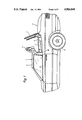
- FIG. 1 is a schematic side view of a motor vehicle with a partially closed folding top, constructed in accordance with a preferred embodiment of the invention
- FIG. 2 is a partial schematic side view depicting the side-wall framework of the folding top according to FIG. 1;
- FIG. 2a is a view showing the structure of FIG. 2 in a position corresponding to a partially shifted main bow
- FIG. 3 is a frontal view of the side-wall framework according to FIG. 2;
- FIG. 3a is a view showing the structure of FIG. 3 in a position corresponding to a partially shifted main bow
- FIG. 4 is an enlarged perspective view showing an upper area of articulation of a roof skin retaining rail of the side-wall framework of FIGS. 1-3;
- FIG. 4a is a view showing the structure of FIG. 4 in a position corresponding to a partially shifted main bow
- FIG. 5 is an enlarged perspective view showing a lowe area of articulation of the roof skin retaining rail on the main bow strut of the side-wall framework of FIGS. 1-3;
- FIG. 5a is a view showing the structure of FIG. 5 in a position corresponding to a partially shifted main bow
- FIG. 6 shows a perspective inner view of the roof skin retaining rail according to FIG. 3, in the area of a locking mechanism
- FIG. 6a is a view showing the structure of FIG. 5 in a position corresponding to a partially shifted main bow
- FIG. 1 there is illustrated a motor car 2 which comprises a supporting top framework which is covered by a roof skin 3 of textile material. Only a roof skin retaining bow of the top framework is visible in FIG. 1, which bow is shown only schematically located in an intermediate position. In this upright intermediate position, a top compartment cover 5, lying underneath the folding top 1 when it is closed, is transferred from its closed position into the open position shown. After release of the front closures of the top, the folding top 1, after being swivelled about a main axis running in vehicle transverse direction, can be lowered in an assigned compartment 6 for the top. Compartment 6 is of U-shaped design and goes around a rear seat area 7.
- the compartment cover 5 for the top can be closed again, so that the folding top 1 is completely concealed.
- the motor car 2 is in this case an aerodynamic model with a pronounced tapering of the rear end of the vehicle. For aerodynamic reasons, this tapering already begins in the area of the rear wheels 8, so that the greatest vehicle width is in front of the rear wheels 8.
- the roof skin 3 is held such that it on the one hand is flush with the rear edge of the side windows 9 and on the other hand slightly overlaps on the outside the lateral side-boards 10 limiting the compartment 6 for the top.
- the closing joint between the compartment cover 5 for the top and the side-boards 10 is also covered, which is desirable in particular for stylistic reasons.
- FIG. 2 shows, apart from the material retaining bow 4, the basic framework parts of a left side wall of the folding top 1.
- the right side wall of the framework of the top is not shown, as it is a mirror image of the left side wall, referred to the center longitudinal plane of the motor car 2.
- the two side walls of the framework of the top are rigidly interconnected in a transverse plane in the usual way by means of a main bow 11 spanning the vehicle width at the roof surface.
- the strut 12 lying in the left side wall of the framework of the top and a assigned section of a bow tube 13 firmly connected to the strut 12 of the top are visible in FIG. 2.
- a bracket (not shown) is firmly connected to the vehicle bodywork.
- the main bow 11 is mounted pivotally about a main axis 14 running perpendicular to the longitudinal center plane of the motor car 2 on the lower ends of the struts 12.
- this strut 12 extends virtually vertically upwards approximately up to the upper edge of the sideboard 10.
- strut 12 includes a section which is inclined obliquely forwards and extends into the proximity of the rear window edge of the side window 9.
- the strut 12 then runs virtually parallel to the rear edge of the side window 9 until it merges into the bow tube 13.
- a rearward end of a roof frame guide arm 15 is articulated on the rear side of the strut 12.
- the roof frame guide arm 15 extends in the side wall plane forwards with a slight downward inclination and is articulated at approximately the center of the upper edge of the side window 9 at its front end on a lateral roof frame 16.
- the roof frame 16 is designed as one piece, extends approximately parallel to the upper edge of the side window 9 and extends up to the strut 12, a rear end section 16a of the roof frame 16 being angled off downwards by approximately 90 degrees, so that it lies in the main direction of extent of the strut 12 in this region.
- a main guide arm 17 is jointedly connected to the lower end of the angled-off end section 16a.
- the main guide arm 17 becomes aligned in its upper longitudinal section with the direction of extent of the rear end section 16a, so that it runs alongside the strut 12.
- guide arm 17 merges into a longitudinal section which continues to be directed downwards and points obliquely rearwards, and ends in a lower end section which is angled off forwards and is designed as control cam 18, by being widened to approximately twice its original width.
- the course of the main guide arm 17 is chosen here such that its lower end section, angled off forwards, covers the obliquely forwards inclined region of the main strut 12, at a vertical distance above the upper edge of the side-board 10. Utilizing this configuration, a joint is provided between the control cam 18 and the main strut 12, the joint axis 19 of which runs perpendicular to the control cam plane.
- the joint axis 20 which runs parallel to the joint axis 19.
- an upper end of a change-over guide arm 21 is mounted on the main guide arm 17.
- the change-over guide arm 21 extends from the joint axis 20, directed downwards slightly to the rear, is curved in the shape of an arc in the middle region and in the lower region consequently takes a course which is directed obliquely forwards.
- the lower end of the change-over guide arm 21 is attached in a joint independent of the struts of the top at the bracket, which joint is defined by the joint axis 22.
- the joint axis 22 runs parallel to the main axis 14 and is offset upwards in relation to the main axis 14 to such an extent that it lies approximately midway between the joint axis 19 and the main axis 14.
- the joint axis 22 is arranged offset forwards in relation to the main axis 14.
- a roof skin retaining rail 24 is articulated on the outside above the joint axis 23 between the main guide arm 17 and the rear end section 16a of the roof frame 16. The articulation takes place in the upper end region of the roof skin retaining rail 24 about a bearing axis 25 running approximately parallel to the center longitudinal axis of the motor car 2.
- the roof skin retaining rail 24 coves the straight longitudinal section of the strut 12, and likewise runs parallel to the rear edge of the side window 9. However, while retaining the direction of extent, its lower end region protrudes downwards beyond the longitudinal section of the strut 12 of the top lying parallel to the rear edge of the side window 9.
- the roof skin 3 is fastened, in a way not shown, to the roof skin retaining rail 24 which holds the roof skin 3 tightly stretched in the connecting region to the side window 9.
- the roof skin 3 is held here in such a way that it adjoins the window 9 with its outside surface flush to it.
- the roof skin retaining rail 24 consists of an angle profile which is bent correspondingly to the convexity of the side window 9. It is in a spread stretching position in which it is swivelled outwards away from the strut 12 about the bearing axis 25 and in which the side inclination of the roof skin 3 is matched to the inclination of the side window 9.
- the lower end of the roof skin retaining rail 24 is cut back from its end face on the inside, so that there remains only on the outside a narrow front end 26.
- the front end 26 covers on the outside an edging 27 raised up from the upper edge of the sideboard 19, so that the roof skin retaining rail 24 can only be swung in again once it has been first moved upwards.
- the roof skin retaining rail 24 is longitudinally displaceable as a whole relative to the strut 12.
- a spreader lever 28 is provided between the strut 12 of and the roof skin retaining rail 24.
- a lower end of the spreader lever 28 is attached on the laterally outward side of the strut 12 at a hinge axis 29 on a level with the joint axis 19.
- the spreader lever 28 extends upward and laterally outwards at an angle of approximately 45 degrees to the strut 12.
- the upper end of spreader lever 28 is articulated at a second hinge axis 30 on the inner lateral surface of the roof skin retaining rail 24.
- the hinge axes 29 and 30 extend parallel with respect to each other and to the axial direction of the bearing axis 25. In this position of the framework of the top, the spreader lever 28 is blocked against swivelling by means of a control mechanism 31, so that the roof skin retaining rail 24 is fixed in this position.
- the spreader lever 28 can be swivelled anti-clockwise about the hinge axis 29 during the course of the swing-back movement of the main bow 11, the hinge axis 30 being moved on a circular path corresponding to the length of the spreader lever 28.
- a sliding guide 32 which can be seen as a detail in FIG. 4, is provided between the bearing axis 25 and the upper end of the roof skin retaining rail 24.
- the sliding guide 32 comprises a cylinder bolt 33, defining the bearing axis 25, and a sliding piece 34 at the upper end of rail 24.
- the cylinder bolt 33 is axially braced by means of a fastening screw 35, which extends through an assigned bore in a bearing plate 36 jutting out from the strut 12 in the motor car transverse direction and is thereby held fixed on the counter-surface of the bearing plate 36. Facing the counter-surface of the bearing plate 36, the cylinder bolt 33 has been machined down to a narrow front pin 37.
- the sliding piece 34 is designed as a hollow box profile, in other words with rectangular clear cross-section. The clear rectangular cross-section is in this case dimensioned such that it is slightly larger than the cross-section of the cylinder bolt 33 in the region of its greatest diameter.
- a longitudinal slit 38 with a U-shaped clear cross-section has been cut out from the rear width side of the sliding piece 34, the clear width of which cross-section is slightly larger than the diameter of the front pin 37. Since the material thickness of the walls limiting the longitudinal slit 38 is smaller than the axial length of the front pin 37, the sliding piece 34 is guided axially and radially on the cylinder bolt 33.
- cap 39 creates a widened bearing surface for the roof skin 3 in the transition region from the roof surface to the side wall surface.
- it is curved in this region in the shape of an arc corresponding to the contour of the motor car and is mounted at its upper end in the direct vicinity of the roof are pivotally about an axis 40 which is fixed to the bearing plate and the axial direction of which runs parallel to the bearing axis 25.
- the deflector cap 39 can yield laterally upwards by being swivelled clockwise about the axis 40.
- a precondition for the desired impact is that the deflector cap 39 is previously in the initial position shown.
- an upwardly facing narrow side of the bearing plate 36 is shaped such that, matched to the deflecting surface contour of the deflector cap 39, it runs inwardly offset, reduced by the amount of the material thickness of the deflector cap 39.
- the bearing plate 36 is thus also effective as a stop for the deflector cap 39, the deflector cap 39 being secured in place by the load of the roof skin 3 resting on it.
- FIG. 5 shows the spreader lever arrangement and the control mechanism 31 as a detail in perspective representation, which makes clear the interaction of these devices.
- the hinge axis 29 is defined by a hinge bolt 41 which is rotatably mounted in a bearing sleeve 42 of a hinge plate 43 fastened on the strut 12.
- the bearing sleeve 42 is not continuous but divided into two sleeve sections by a separating gap 44 in the front half of its longitudinal extent.
- the spreader lever 28 is designed in the shape of fork where it faces the bearing sleeve 42, the fork ends 45 being connected fixedly in terms of rotation to the hinge bolt 41, in the region of the separating gap 44 on the one hand and in front of the bearing sleeve 42, from which one end of the hinge bolt 41 protrudes, on the other hand.
- This type of articulation of the spreader lever 28 produces a particularly stable support of the roof skin retaining rail 24 in the region of its lower end.
- a driving finger 46 which is of wedge-shaped design and protrudes from under the strut transversely into the swivelling plane of the control cam 18. Its free end passes here through a through-opening 47, which is cut out from the opposite control cam 18.
- the through-opening 47 is located at the front end of a ditch-like depression 48, which serves as control track for the driving finger 46.
- the depression 48 runs on a circular path around the joint axis 19, its longitudinal extent being matched to the relative deflection of the main guide arm 17 to the strut 12.
- a link 49 is disengaged from the bottom of the depression 48 and put out into a transversely jutting blocking position facing the strut 12, in which position it engages underneath the driving finger 46.
- the link 49 thus serves as a blocking stop, by which the driving finger 46 is reliably held in the clamped position shown.
- the clear length of the through-opening is dimensioned such that the engaging driving finger 46 can be tilted in it while maintaining the engagement if the main guide arm 17 is swung anti-clockwise.
- the clear depth of the depression 4 is matched to the length of the driving finger 46 in such a way that, in the tilted state, the free end of the driving finger 46 is supported on the bottom of the depression 48 when the main guide arm 17 is swivelled further. As a result, the driving finger 46 is blocked in a lower swivel position as long as the end of the driving finger 46 bears against the bottom of the depression 48.
- FIG. 6 shows an individual representation of a lock 50 between the rear end section 16a of the roof frame 16 and the roof skin retaining rail 24 along the line of intersection VI--VI in FIG. 3.
- FIGS. 6 and 6a the upper end of rail 24 with sliding piece 34 is only schematically depicted.
- This lock 50 serves the purpose of relieving the spreader lever 28 and the control mechanism 31 when the folding top 1 is closed since, in this operating state, these components would otherwise be exposed to a continuous stress due to the stretched roof skin 3 and any twisting of the bodywork.
- a transverse pin 51 juts out from the lateral side of the rear end section 16a facing the roof skin retaining rail 24, which transverse pin is rigidly connected to the said end section, has a conical shape and tapers towards the roof skin retaining rail 24.
- the transverse pin 51 lies snugly in a clear entry cross-section 52 of an abutment 53, which is fastened oppositely on the width side of the roof skin retaining rail 24.
- the abutment 53 is of wedge-shaped design, matched to the angle formed between the roof skin retaining rail 24 and the longitudinal extent of the end section 16a, so that it lies flush on the lateral side of the end section 16a.
- the clear width of the entry cross-section 52 widens increasingly forwards, seen in vehicle longitudinal direction, from the seat of the transverse pin 51. This produces an automatic centering of the transverse pin 51 when the latter enters the assigned fork-shaped abutment 53 during the course of the closing operation of the folding top 1.
- the folding top 1 can be lowered in the assigned compartment 6 for the top by shifting of the main bow 11, which corresponds to a swivelling operation of the strut 12 of the top from the upright position according to FIG. 2 through an angle of approximately 90 degrees clockwise about the main axis 14. All other framework parts are moved at the same time by means of the main bow 11 and are forcibly controlled kinematically dependently on the swivel angle of the bow 11 at the time.
- the reduction in the swivelling range of the folding top 1 takes place in this case in the first folding phase. During the course of this first folding phase, which has just been concluded after reaching the position shown in FIG.
- the articulation point of the roof frame guide arm 15 on the strut 12 moves rearwards on a circular path around the main axis 14, the lateral roof frame 16 being taken along by means of the front articulation of the roof frame guide arm 15.
- the main guide arm 17 Due to the fixed support to the bodywork of the joint axis 20 by means of the change-over guide arm 21, the main guide arm 17 cannot take part in the swivelling movement of the strut 12 of the top in the same direction, so that it is swivelled anti-clockwise about the joint axis 19 fixed to the roof strut.
- the joint axis 23 is thereby moved forwards and the front articulation point of the roof frame guide arm 15 is moved backwards.
- the dependently moved lateral roof frame 16 is in this case forcibly swivelled clockwise about the joint axis 23, jutting upwards virtually vertically after conclusion of the first folding phase. If the folding operation is continued, the roof frame 16 is turned through a total of approximately 180 degrees and lies in its end position above the assigned strut 12 in the compartment 6 for the top.
- the material retaining rail 24 is simultaneously transferred from the spread-apart stretching position which can be seen in FIG. 3 into a folding position nearer to the strut according to FIG. 3a, in which the material retaining rail 24 lies closely alongside the strut 12 of the top.
- This folded position comes about as follows:
- the control cam 18 integrated in the main guide arm 17 is also moved with it in the same direction. Consequently, the through-opening 47 also moves anti-clockwise on a circular path around the joint axis 19.
- the wall of the control cam 18 limiting the through-opening 47 upwards presses the free end of the driving finger 46 downwards, as a result of which the driving finger 46 is swivelled clockwise about the hinge axis 29 fixed to the strut 12.
- the hinge bolt 41 thereby transfers the swivelling movement of the driving finger 46 onto the spreader lever 28, so that the latter takes part in the swivelling movement of the driving finger 46 in the same direction.
- the roof skin retaining rail 24 is displaced upwards in the direction of its longitudinal axis and at the same time folded in in the direction toward the strut 12.
- the axial component of this advancement is in this case accommodated by the sliding guide 32, the narrow sides of the sliding piece 34, limiting the longitudinal slit 38, sliding upwards on the circumference of the front pin 37.
- the upper end of the sliding piece 34 hits the rear deflecting surface of the deflector cap 39 and causes a slight lifting of the deflector cap 39 off the bearing plate 36, during which the roof skin 3 is gently pushed away upwards. Since the axial advancement of the roof skin retaining rail 24 is superimposed by the transverse advancement, the sliding operation of the sliding piece 34 on the front pin 37 accompanies a turning movement of the sliding piece 34 about the front pin 37, the roof skin retaining rail 24 being held on the front pin 37 in the turning-sliding position by support of the sliding piece 34 on the enclosed cylinder bolt 33.
- the roof skin retaining rail 24 In the upper folded-in end position according to FIG. 5a, the roof skin retaining rail 24 must be fixed as long as the folding top 1 is not in the first opening phase or the final closing phase.
- the length of the through-opening 47 and the extent of the depth of the depression 48 are matched to the length of the driving finger 46 such that, after conclusion of the adjustment operation of the roof skin retaining rail 24, the said driving finger is turned out of the clear cross-section of the through-opening 47 and, in downward inclination, is supported by its end on the bottom of the depression 48.
- the depression 48 has a constant clear cross-section, during further swivelling of the main guide arm 17, the end of the driving finger 46 slides along on the bottom of the depression 48 without changing the angular position of the driving finger 46 with respect to the control cam 18. In order that no grinding noises can occur in this case, the depression 48 is correspondingly lubricated. In this swivelling phase of the main guide arm 17, the spreader lever 28, and consequently the roof skin retaining rail 24, are also blocked by means of the blocked driving finger 46.
- the driving finger 46 Only when the main guide arm 17 is again swivelled clockwise during the course of the closing operation of the folding top can the driving finger 46 again change its angular position with respect to the control cam 18, as soon as the end reenters the clear cross-section of the through-opening 46. Thereafter, with the link 49 hitting the free end of the driving finger 46 during the course of the final closing phase of the folding top 1, the driving finger is forcibly transferred by a position swivelled anti-clockwise through approximately 90 degrees according to FIG. 5, the roof skin retaining rail 24 forcibly reassuming its extended stretching position.
- This operation takes place at the same time as the locking operation of the roof skin retaining rail 24.
- the end section 16a is already in the proximity of the roof skin retaining rail 24 and, with control by the main guide arm 17, is transferred during the course of the further closing movement of the folding top 1 into the transverse plane of the roof skin retaining rail 24.
- the transverse pin 51 is automatically introduced into the entry cross-section 52 of the abutment 53, an automatic centering of the roof skin retaining rail 24 being produced due to the wedge-shaped design of the limiting surfaces of the entry cross-section 52. Consequently, at the moment the spread-apart stretching position of thereof skin retaining rail 24 is reached, it is also already in its axially locked end position.
Landscapes
- Engineering & Computer Science (AREA)
- Mechanical Engineering (AREA)
- Body Structure For Vehicles (AREA)
- Lock And Its Accessories (AREA)
Abstract
Description
Claims (29)
Applications Claiming Priority (2)
| Application Number | Priority Date | Filing Date | Title |
|---|---|---|---|
| DE3724533A DE3724533C1 (en) | 1987-07-24 | 1987-07-24 | Folding roof for vehicles |
| DE3724533 | 1987-07-24 |
Publications (1)
| Publication Number | Publication Date |
|---|---|
| US4984841A true US4984841A (en) | 1991-01-15 |
Family
ID=6332276
Family Applications (1)
| Application Number | Title | Priority Date | Filing Date |
|---|---|---|---|
| US07/223,367 Expired - Fee Related US4984841A (en) | 1987-07-24 | 1988-07-25 | Folding top for vehicles |
Country Status (6)
| Country | Link |
|---|---|
| US (1) | US4984841A (en) |
| JP (1) | JPH0741799B2 (en) |
| DE (1) | DE3724533C1 (en) |
| FR (1) | FR2618390B1 (en) |
| GB (1) | GB2207099B (en) |
| IT (1) | IT1219642B (en) |
Cited By (16)
| Publication number | Priority date | Publication date | Assignee | Title |
|---|---|---|---|---|
| US5106145A (en) * | 1991-01-31 | 1992-04-21 | Asc Incorporated | Convertible stack system |
| WO1992018343A1 (en) * | 1991-04-11 | 1992-10-29 | Asc Incorporated | Convertible top with improved geometry |
| US5593202A (en) * | 1993-01-04 | 1997-01-14 | Asc Incorporated | Convertible top |
| US5678881A (en) * | 1992-09-04 | 1997-10-21 | Asc Incorporated | Apparatus and method for securing a convertible roof to an automotive vehicle |
| US5743587A (en) * | 1993-12-29 | 1998-04-28 | Asc Incorporated | Apparatus for use in an automotive vehicle having a convertible roof system |
| US5779299A (en) * | 1995-06-07 | 1998-07-14 | Asc Incorporated | Apparatus for achieving automotive vehicle roof isolation |
| US5785375A (en) * | 1993-12-29 | 1998-07-28 | Asc Incorporated | Retractable hard-top for an automotive vehicle |
| USD406792S (en) * | 1997-03-25 | 1999-03-16 | Asc Incorporated | Portion of automotive vehicle having a convertible roof |
| US6042174A (en) * | 1997-08-22 | 2000-03-28 | Asc Incorporated | Latching and control apparatus for an automotive vehicle convertible roof |
| USD427138S (en) * | 1997-03-25 | 2000-06-27 | Asc Incorporated | Portion of a convertible roof and tonneau cover |
| USD442541S1 (en) | 1993-12-29 | 2001-05-22 | Asc Incorporated | Portion of an opaque convertible roof |
| USRE38546E1 (en) * | 1993-01-04 | 2004-07-06 | Asc Incorporated | Convertible top |
| US20040232721A1 (en) * | 2001-10-20 | 2004-11-25 | Rawlings Stephen P | Folding convertible top with integral boot |
| US6832805B2 (en) | 2002-10-02 | 2004-12-21 | Wilhelm Karmann Gmbh | Convertible top system for vehicle |
| US6957842B1 (en) | 2004-04-30 | 2005-10-25 | Asc Incorporated | Convertible roof bow tensioning apparatus |
| CN112693543A (en) * | 2021-01-27 | 2021-04-23 | 苏州凯尔博精密机械有限公司 | Accurate skin tracing laminating forming equipment |
Families Citing this family (8)
| Publication number | Priority date | Publication date | Assignee | Title |
|---|---|---|---|---|
| DE3915867C1 (en) * | 1989-05-16 | 1990-06-13 | Daimler-Benz Aktiengesellschaft, 7000 Stuttgart, De | |
| US5067768A (en) * | 1989-10-23 | 1991-11-26 | Wickes Manufacturing Company | Power convertible top with automatic top and tonneau sequencing |
| DE29710720U1 (en) * | 1997-06-19 | 1998-04-02 | Wilhelm Karmann GmbH, 49084 Osnabrück | Convertible top for a convertible vehicle |
| DE19962995B4 (en) * | 1999-12-24 | 2008-06-12 | Wilhelm Karmann Gmbh | Convertible vehicle with an at least partially flexible roof |
| DE10160240B4 (en) * | 2001-12-07 | 2005-04-07 | Webasto Ag | Folding hood for a motor vehicle |
| DE102004003020A1 (en) * | 2004-01-20 | 2005-08-11 | Wilhelm Karmann Gmbh | Convertible car |
| US7287801B2 (en) * | 2005-04-26 | 2007-10-30 | Harrison Iii Albert W | Convertible top mechanism with inwardly articulating rearmost lateral rails |
| DE102007015041B4 (en) * | 2007-03-29 | 2021-07-29 | Valmet Automotive Oy | Cabriolet vehicle with a protruding pillar part of the roof |
Citations (3)
| Publication number | Priority date | Publication date | Assignee | Title |
|---|---|---|---|---|
| GB2154955A (en) * | 1984-02-18 | 1985-09-18 | Daimler Benz Ag | Folding hood for vehicles |
| US4712828A (en) * | 1985-11-07 | 1987-12-15 | California Auto Trends | Convertible top apparatus for midengine automobiles |
| US4720134A (en) * | 1985-06-29 | 1988-01-19 | Daimler-Benz Aktiengesellshaft | Convertible top for vehicles, especially for passenger motor vehicles |
Family Cites Families (2)
| Publication number | Priority date | Publication date | Assignee | Title |
|---|---|---|---|---|
| US3075804A (en) * | 1959-03-05 | 1963-01-29 | Daimler Benz Ag | Foldable roof construction, especially for motor vehicles |
| DE1212423B (en) * | 1962-02-24 | 1966-03-10 | Hans Glas G M B H | Fully retractable convertible top |
-
1987
- 1987-07-24 DE DE3724533A patent/DE3724533C1/en not_active Expired
-
1988
- 1988-06-14 IT IT48079/88A patent/IT1219642B/en active
- 1988-07-22 JP JP63181938A patent/JPH0741799B2/en not_active Expired - Lifetime
- 1988-07-22 FR FR888809928A patent/FR2618390B1/en not_active Expired - Fee Related
- 1988-07-22 GB GB8817462A patent/GB2207099B/en not_active Expired - Fee Related
- 1988-07-25 US US07/223,367 patent/US4984841A/en not_active Expired - Fee Related
Patent Citations (3)
| Publication number | Priority date | Publication date | Assignee | Title |
|---|---|---|---|---|
| GB2154955A (en) * | 1984-02-18 | 1985-09-18 | Daimler Benz Ag | Folding hood for vehicles |
| US4720134A (en) * | 1985-06-29 | 1988-01-19 | Daimler-Benz Aktiengesellshaft | Convertible top for vehicles, especially for passenger motor vehicles |
| US4712828A (en) * | 1985-11-07 | 1987-12-15 | California Auto Trends | Convertible top apparatus for midengine automobiles |
Cited By (26)
| Publication number | Priority date | Publication date | Assignee | Title |
|---|---|---|---|---|
| US5106145A (en) * | 1991-01-31 | 1992-04-21 | Asc Incorporated | Convertible stack system |
| WO1992018343A1 (en) * | 1991-04-11 | 1992-10-29 | Asc Incorporated | Convertible top with improved geometry |
| US5161852A (en) * | 1991-04-11 | 1992-11-10 | Asc Incorporated | Convertible top with improved geometry |
| US5678881A (en) * | 1992-09-04 | 1997-10-21 | Asc Incorporated | Apparatus and method for securing a convertible roof to an automotive vehicle |
| US5593202A (en) * | 1993-01-04 | 1997-01-14 | Asc Incorporated | Convertible top |
| US5810422A (en) * | 1993-01-04 | 1998-09-22 | Asc Incorporated | Convertible top |
| USRE38546E1 (en) * | 1993-01-04 | 2004-07-06 | Asc Incorporated | Convertible top |
| USD442541S1 (en) | 1993-12-29 | 2001-05-22 | Asc Incorporated | Portion of an opaque convertible roof |
| US5743587A (en) * | 1993-12-29 | 1998-04-28 | Asc Incorporated | Apparatus for use in an automotive vehicle having a convertible roof system |
| US5785375A (en) * | 1993-12-29 | 1998-07-28 | Asc Incorporated | Retractable hard-top for an automotive vehicle |
| USD464605S1 (en) | 1993-12-29 | 2002-10-22 | Asc Incorporated | Combined automotive convertible roof, tonneau cover and rear compartment lid |
| USD452675S1 (en) | 1993-12-29 | 2002-01-01 | Asc Incorporated | Combined automotive convertible roof portion and tonneau cover |
| US5779299A (en) * | 1995-06-07 | 1998-07-14 | Asc Incorporated | Apparatus for achieving automotive vehicle roof isolation |
| USD427138S (en) * | 1997-03-25 | 2000-06-27 | Asc Incorporated | Portion of a convertible roof and tonneau cover |
| USD406792S (en) * | 1997-03-25 | 1999-03-16 | Asc Incorporated | Portion of automotive vehicle having a convertible roof |
| US6042174A (en) * | 1997-08-22 | 2000-03-28 | Asc Incorporated | Latching and control apparatus for an automotive vehicle convertible roof |
| US20040232721A1 (en) * | 2001-10-20 | 2004-11-25 | Rawlings Stephen P | Folding convertible top with integral boot |
| US7163255B2 (en) | 2001-10-20 | 2007-01-16 | Dura Convertible Systems, Inc. | Folding convertible top with integral boot |
| US7021695B2 (en) | 2002-10-02 | 2006-04-04 | Wilhelm Karmann Gmbh | Convertible top system for vehicle |
| US20050088008A1 (en) * | 2002-10-02 | 2005-04-28 | Quindt Reinhard W. | Convertible top system for vehicle |
| US6832805B2 (en) | 2002-10-02 | 2004-12-21 | Wilhelm Karmann Gmbh | Convertible top system for vehicle |
| US6957842B1 (en) | 2004-04-30 | 2005-10-25 | Asc Incorporated | Convertible roof bow tensioning apparatus |
| US20050242615A1 (en) * | 2004-04-30 | 2005-11-03 | Garska Bradley R | Convertible roof bow tensioning apparatus |
| US20060061130A1 (en) * | 2004-04-30 | 2006-03-23 | Asc Incorporated | Convertible roof bow tensioning apparatus |
| US7380863B2 (en) | 2004-04-30 | 2008-06-03 | Specialty Vehicle Aquisition Corp. | Convertible roof bow tensioning apparatus |
| CN112693543A (en) * | 2021-01-27 | 2021-04-23 | 苏州凯尔博精密机械有限公司 | Accurate skin tracing laminating forming equipment |
Also Published As
| Publication number | Publication date |
|---|---|
| GB2207099A (en) | 1989-01-25 |
| FR2618390A1 (en) | 1989-01-27 |
| IT8848079A0 (en) | 1988-06-14 |
| GB2207099B (en) | 1991-11-13 |
| FR2618390B1 (en) | 1991-02-01 |
| GB8817462D0 (en) | 1988-08-24 |
| IT1219642B (en) | 1990-05-24 |
| DE3724533C1 (en) | 1988-11-10 |
| JPS6444325A (en) | 1989-02-16 |
| JPH0741799B2 (en) | 1995-05-10 |
Similar Documents
| Publication | Publication Date | Title |
|---|---|---|
| US4984841A (en) | Folding top for vehicles | |
| US5004291A (en) | Top framework of a folding top for vehicles | |
| US5975619A (en) | Folding top for vehicles | |
| US5823606A (en) | Hard-top vehicle | |
| US6666494B2 (en) | Folding convertible top for a motor vehicle | |
| US6139087A (en) | Kinematic folding top for passenger cars | |
| US6312041B1 (en) | Collapsible roof for vehicle such as a truck, van or break | |
| US6270143B1 (en) | Folding roof for a convertible | |
| JP4636350B2 (en) | Folding top for cabriolet | |
| US5816644A (en) | Folding top for a convertible | |
| US5746470A (en) | Hard-top vehicle | |
| DE4038074C1 (en) | Roof for cabriolet vehicle - has roof pivoting on two support link rods hinged on lateral supports | |
| US6039383A (en) | Roof construction for a motor vehicle | |
| EP1164041B1 (en) | Convertible vehicle | |
| US5788316A (en) | Folding top for a convertible | |
| US6123381A (en) | Device for stowing the roof structure of a hardtop vehicle | |
| US6550842B1 (en) | Folding top for a motor vehicle | |
| US5435406A (en) | Vehicle hood mounting arrangement | |
| US20010042991A1 (en) | Folding top for vehicles, in particular passenger cars | |
| US6322130B1 (en) | Folding top mechanism for a convertible, rollover protection system, and a convertible | |
| US4720134A (en) | Convertible top for vehicles, especially for passenger motor vehicles | |
| GB2333745A (en) | Rear lid mounting mechanism for a convertible motor vehicle | |
| EP0521307A1 (en) | Folding hood for motorvehicle provided with a collapsible roof | |
| US6142555A (en) | Collapsible hard top for a convertible motor vehicle | |
| US6416121B1 (en) | Folding top mechanism of a folding roof for a convertible |
Legal Events
| Date | Code | Title | Description |
|---|---|---|---|
| AS | Assignment |
Owner name: DAIMLER-BENZ AKTIENGESELLSCHAFT, STUTTGART, FEDERA Free format text: ASSIGNMENT OF ASSIGNORS INTEREST.;ASSIGNORS:BAUER, THEODOR;ZWEIGART, GERHARD;GRAMER, KURT;REEL/FRAME:004961/0719;SIGNING DATES FROM 19880721 TO 19880801 Owner name: DAIMLER-BENZ AKTIENGESELLSCHAFT, GERMANY Free format text: ASSIGNMENT OF ASSIGNORS INTEREST;ASSIGNORS:BAUER, THEODOR;ZWEIGART, GERHARD;GRAMER, KURT;SIGNING DATES FROM 19880721 TO 19880801;REEL/FRAME:004961/0719 |
|
| FEPP | Fee payment procedure |
Free format text: PAYOR NUMBER ASSIGNED (ORIGINAL EVENT CODE: ASPN); ENTITY STATUS OF PATENT OWNER: LARGE ENTITY |
|
| FPAY | Fee payment |
Year of fee payment: 4 |
|
| FEPP | Fee payment procedure |
Free format text: PAYOR NUMBER ASSIGNED (ORIGINAL EVENT CODE: ASPN); ENTITY STATUS OF PATENT OWNER: LARGE ENTITY Free format text: PAYER NUMBER DE-ASSIGNED (ORIGINAL EVENT CODE: RMPN); ENTITY STATUS OF PATENT OWNER: LARGE ENTITY |
|
| FPAY | Fee payment |
Year of fee payment: 8 |
|
| FEPP | Fee payment procedure |
Free format text: PAYOR NUMBER ASSIGNED (ORIGINAL EVENT CODE: ASPN); ENTITY STATUS OF PATENT OWNER: LARGE ENTITY Free format text: PAYER NUMBER DE-ASSIGNED (ORIGINAL EVENT CODE: RMPN); ENTITY STATUS OF PATENT OWNER: LARGE ENTITY |
|
| REMI | Maintenance fee reminder mailed | ||
| LAPS | Lapse for failure to pay maintenance fees | ||
| STCH | Information on status: patent discontinuation |
Free format text: PATENT EXPIRED DUE TO NONPAYMENT OF MAINTENANCE FEES UNDER 37 CFR 1.362 |
|
| FP | Lapsed due to failure to pay maintenance fee |
Effective date: 20030115 |