US498286A - Hanging gutter - Google Patents
Hanging gutter Download PDFInfo
- Publication number
- US498286A US498286A US498286DA US498286A US 498286 A US498286 A US 498286A US 498286D A US498286D A US 498286DA US 498286 A US498286 A US 498286A
- Authority
- US
- United States
- Prior art keywords
- gutter
- sections
- joints
- fold
- section
- Prior art date
- Legal status (The legal status is an assumption and is not a legal conclusion. Google has not performed a legal analysis and makes no representation as to the accuracy of the status listed.)
- Expired - Lifetime
Links
- 239000011324 bead Substances 0.000 description 3
- 230000015572 biosynthetic process Effects 0.000 description 3
- 238000010276 construction Methods 0.000 description 3
- 230000008878 coupling Effects 0.000 description 2
- 238000010168 coupling process Methods 0.000 description 2
- 238000005859 coupling reaction Methods 0.000 description 2
- 238000003780 insertion Methods 0.000 description 2
- 230000037431 insertion Effects 0.000 description 2
- 239000000463 material Substances 0.000 description 2
- 229910000679 solder Inorganic materials 0.000 description 2
- 208000027418 Wounds and injury Diseases 0.000 description 1
- 235000019994 cava Nutrition 0.000 description 1
- 230000006378 damage Effects 0.000 description 1
- 210000002478 hand joint Anatomy 0.000 description 1
- 208000014674 injury Diseases 0.000 description 1
- 239000002184 metal Substances 0.000 description 1
- 238000000034 method Methods 0.000 description 1
- 239000000126 substance Substances 0.000 description 1
Images
Classifications
-
- E—FIXED CONSTRUCTIONS
- E04—BUILDING
- E04D—ROOF COVERINGS; SKY-LIGHTS; GUTTERS; ROOF-WORKING TOOLS
- E04D13/00—Special arrangements or devices in connection with roof coverings; Protection against birds; Roof drainage ; Sky-lights
- E04D13/04—Roof drainage; Drainage fittings in flat roofs, balconies or the like
- E04D13/064—Gutters
- E04D13/068—Means for fastening gutter parts together
Definitions
- My invention relates to the improvement of caves troughs or hanging gutters for buildings and the objects of my invention are, to provide a simple, reliable and effective means of coupling the joints or sections of an eaves trough; to obviate the necessity of employing solder in said connection; to so construct my improved trough as to admit of its sections being rapidly and securely coupled in any desired lengths and to produce other improvements which will be more specifically pointed out hereinafter.
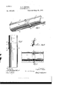
- Figure 1 is a view in perspective of two sections of eaves trough showing the same united by my improved coupling.
- Fig. 2 is a central longitudinal section of portions of two united joints.
- Fig. 3 is atransverse section on line a: x of Fig. 4 and
- Fig. 4 is a bottom view of the jointed sections of two sections.
- a (1 represent respectively, joints or sections or portions of joints or sections of my improved gutter, each of said joints being formed of suitable sheet metal and having the usual concaved or gutter shape.
- the upper longitudinal edges of these sections are bent outward and thence upward to form substantially L-shaped flanges b, the vertical or upwardly projecting portions of these flanges being doubled, as shown at b.
- substantially hook shaped edges are formed which will admit of the edges of one section being engaged with the edges of another:
- each of the gutter sections I extend the concaved or gutter portion at one end thereof.
- This extended portion which is indicated at c is as shown at c, folded or bent backward upon the under convex surface of the gutter joint body, the portion thus folded being again bent or folded forward, upon itself, as indicated at d in Fig. 2.
- This last fold d is made at such point in the extension 0 as to cause the outer fold leaf 01 produced thereby to extend forwardly beyond the first fold c.
- I cause the outer leaf d thereof to extend parallel with the leaf of the first fold c and at a short distance from the latter.
- the fold extension-portion c of the gutter joint is bent to conform to the outline of the convex portion of the gutter, the inner fold leaf produced by the fold 0 being pressed closely into engagement with the outer surface of the gutter section.
- I provide the opposite end of the gutter section or joint, from that above described, with a slightly out-turned or sprung edge. (Indicated at e.)
- said fold leaf d will readily spring into its 100 place against the surface of the inserted portion of the section, thus forming a close connection between the two sections or joints.
- f represents a transverse hanger or crossbar which extends between the sides of the gutter immediately over the joining point of two sections.
- This bar hanger rests at opposite points upon the bases or horizontal portions of the flanges b and has its end portions bent or shaped to fit or fold about said flange portions b, as shown.
- the ends of this bar f are as shown in Fig. 4 of the drawings, made pointed said pointed ends being as shown in Fig. 3 of the drawings, forced into the material forming one of the jointed sections, as
- hanger bars will not only provide means for suspending the gutter, but that said bars will serve as cross-braces at the joints of said gutter and assist in the operation of retaining the sections in close connection.
- an eaves trough for hanging gutters the combination of the trough sections a, an extension 0 on one end of each of said sections, said extended portion being folded backward upon the body of said section and refolded to form a curved socket having as described an off-set at its inner end produced by the formation of the bead d, the opposite end of each of said gutter sections having an outward bend, or flare e, the socket of one section adapted to receive as described, the flaring end of another, substantially as and for the purpose specified.
Landscapes
- Engineering & Computer Science (AREA)
- Architecture (AREA)
- Civil Engineering (AREA)
- Structural Engineering (AREA)
- Mutual Connection Of Rods And Tubes (AREA)
Description
0. 0. MOORE. HANGING GUTTER.
(No Model.)-
Patented May 30, 1893.
Swen/we Chufles QSWmve.
M aw! W UNITE STATES PATENT OFFICE.
CHARLES CLINTON MOORE, OF COLUMBUS, OHIO.
-HANG|NG GUT'CI'ER.
SPECIFICATION forming part of Letters Patent No. 498,286, dated May 30, 1893.
Application filed November 28,1892. Serial No. 453,430. (No model.)
To all whom it may concern! Be it known that I, CHARLES CLINTON MOORE, a citizen of the United States, residing at Columbus, in the county of Franklin and State of Ohio, have invented a certain new and useful Improvement in Eaves-Troughs or Hanging Gutters, of which the following is a specification.
My invention relates to the improvement of caves troughs or hanging gutters for buildings and the objects of my invention are, to provide a simple, reliable and effective means of coupling the joints or sections of an eaves trough; to obviate the necessity of employing solder in said connection; to so construct my improved trough as to admit of its sections being rapidly and securely coupled in any desired lengths and to produce other improvements which will be more specifically pointed out hereinafter. These objects I accomplish in the manner illustrated in the accompanying drawings, in which Figure 1 is a view in perspective of two sections of eaves trough showing the same united by my improved coupling. Fig. 2 is a central longitudinal section of portions of two united joints. Fig. 3 is atransverse section on line a: x of Fig. 4 and Fig. 4 is a bottom view of the jointed sections of two sections.
Similar letters refer to similar parts throughout the several views.
a (1 represent respectively, joints or sections or portions of joints or sections of my improved gutter, each of said joints being formed of suitable sheet metal and having the usual concaved or gutter shape. Asshown in the drawings, the upper longitudinal edges of these sections are bent outward and thence upward to form substantially L-shaped flanges b, the vertical or upwardly projecting portions of these flanges being doubled, as shown at b. In this manner substantially hook shaped edges are formed which will admit of the edges of one section being engaged with the edges of another: I
In the formation of each of the gutter sections above mentioned, I extend the concaved or gutter portion at one end thereof. This extended portion which is indicated at c is as shown at c, folded or bent backward upon the under convex surface of the gutter joint body, the portion thus folded being again bent or folded forward, upon itself, as indicated at d in Fig. 2. This last fold d is made at such point in the extension 0 as to cause the outer fold leaf 01 produced thereby to extend forwardly beyond the first fold c. In forming the last fold d, I cause the outer leaf d thereof to extend parallel with the leaf of the first fold c and at a short distance from the latter. At the folding point d,Ialso produce a slight outward bend of the material so folded, resulting as shown in the formation when viewed from the exterior of the joint in a bead or struck-up portion d while the leaf d is at its outer or forward end also bent outward and thence inward to form a correspondingly shapedlip bead 0Z As shown in the drawings, the fold extension-portion c of the gutter joint is bent to conform to the outline of the convex portion of the gutter, the inner fold leaf produced by the fold 0 being pressed closely into engagement with the outer surface of the gutter section. As shown more plainly in Fig. 2 of the drawings, I provide the opposite end of the gutter section or joint, from that above described, with a slightly out-turned or sprung edge. (Indicated at e.)
In connecting two of the gutter sections above described, I insert the sprung end portion 6 of one section beneath the bead-shaped lip 61 of the fold d and within the socket between said leaf d and the inner leaf of the extension 0 of the adjoining section. The insertion being complete, it will be seen thatv the flaring or sprung end e of the section will spring outward into the seat formed at the end of said socket by the out-turned or beaded projection 01 said seat thus serving to form a shoulder with which said flaring end 6 may engage. It is evident that during the insertion of one section within the socket of the other as above described, the outturned'end portion 6 may by contact with the fold leaf d press the latter slightly outward and that when said out-turned end 6 has reached its inner seat as above described,
said fold leaf d will readily spring into its 100 place against the surface of the inserted portion of the section, thus forming a close connection between the two sections or joints.
f represents a transverse hanger or crossbar which extends between the sides of the gutter immediately over the joining point of two sections. This bar hanger rests at opposite points upon the bases or horizontal portions of the flanges b and has its end portions bent or shaped to fit or fold about said flange portions b, as shown. The ends of this bar f are as shown in Fig. 4 of the drawings, made pointed said pointed ends being as shown in Fig. 3 of the drawings, forced into the material forming one of the jointed sections, as
shown at g. It will thus be seen that the hanger bars will not only provide means for suspending the gutter, but that said bars will serve as cross-braces at the joints of said gutter and assist in the operation of retaining the sections in close connection.
From the construction herein shown and described, it will be seen that means are provided for establishing a connection between the joints or sections of eaves trough which obviates the necessity of employing solder or other similar substance to produce said connection. It will also be seen that the herein described construction is such as to render the gutter or trough completely water-tight at the joints and admit of said joints being readily and easily produced.
Owing to the character of the connection herein shown, it is evident that I may produce the gutter sections in any desired lengths and that if desired, the trough may be readily unjointed or taken apart without injury to the sections thereof.
It will be observed that the method of connection which I employ is such as to obviate the necessity of the use of what are termed ordinarily right and left hand joints that is each alternate joint of a length of gutter formed to fit within or connect with the intervening joints. It will thus be observed that the joints of my improved device are interchangeable being of the same construction and one joint to be adapted to be connected with the other.
Having now fully described my invention, what I claim, and desire to secure by Letters Patent, is-
In an eaves trough for hanging gutters, the combination of the trough sections a, an extension 0 on one end of each of said sections, said extended portion being folded backward upon the body of said section and refolded to form a curved socket having as described an off-set at its inner end produced by the formation of the bead d, the opposite end of each of said gutter sections having an outward bend, or flare e, the socket of one section adapted to receive as described, the flaring end of another, substantially as and for the purpose specified.
CHARLES CLINTON MOORE.
In presence ot- BARTON GRIFFITH, O. E. IIOLDSWORTH.
Publications (1)
| Publication Number | Publication Date |
|---|---|
| US498286A true US498286A (en) | 1893-05-30 |
Family
ID=2567121
Family Applications (1)
| Application Number | Title | Priority Date | Filing Date |
|---|---|---|---|
| US498286D Expired - Lifetime US498286A (en) | Hanging gutter |
Country Status (1)
| Country | Link |
|---|---|
| US (1) | US498286A (en) |
Cited By (1)
| Publication number | Priority date | Publication date | Assignee | Title |
|---|---|---|---|---|
| US20230027949A1 (en) * | 2021-07-15 | 2023-01-26 | Stephane Brochu | Gutter Assembly and Method for Installing a Gutter |
-
0
- US US498286D patent/US498286A/en not_active Expired - Lifetime
Cited By (2)
| Publication number | Priority date | Publication date | Assignee | Title |
|---|---|---|---|---|
| US20230027949A1 (en) * | 2021-07-15 | 2023-01-26 | Stephane Brochu | Gutter Assembly and Method for Installing a Gutter |
| US12091860B2 (en) * | 2021-07-15 | 2024-09-17 | Stephane Brochu | Gutter assembly and method for installing a gutter |
Similar Documents
| Publication | Publication Date | Title |
|---|---|---|
| US2821154A (en) | Couplings for joining lengths of trough gutters | |
| US926423A (en) | Metal-cased pipe-covering. | |
| US334160A (en) | Eaves-trough | |
| US1126854A (en) | Roof-gutter. | |
| US230396A (en) | bokbrak | |
| US401202A (en) | Thomas o gara | |
| US806304A (en) | Desk. | |
| US370073A (en) | Eaves-trough hanger | |
| US1160124A (en) | Eaves-trough hanger. | |
| US172841A (en) | Improvement in eaves-trough hangers | |
| US460982A (en) | Eaves-trough | |
| US350909A (en) | Eaves-trough hanger | |
| US415224A (en) | Slip-joint for sheet-metal cornices | |
| US508366A (en) | Eaves-trough | |
| US239880A (en) | Eaves-trough hanger | |
| US145641A (en) | Improvement in couplings for tubular lightning-rods | |
| US609488A (en) | Hose-coupling | |
| US1566284A (en) | Gutter hanger | |
| US834493A (en) | Garment-clasp. | |
| US1012764A (en) | Drain-spout. | |
| US369708A (en) | Eaves-trough hanger | |
| US434310A (en) | John woek | |
| US390122A (en) | Geoege a | |
| US183988A (en) | Improvement in eaves-trough hangers | |
| US432408A (en) | Snow-guard |