US4974635A - Coupler with spring-locked valves - Google Patents
Coupler with spring-locked valves Download PDFInfo
- Publication number
- US4974635A US4974635A US07/345,389 US34538989A US4974635A US 4974635 A US4974635 A US 4974635A US 34538989 A US34538989 A US 34538989A US 4974635 A US4974635 A US 4974635A
- Authority
- US
- United States
- Prior art keywords
- valve
- ring
- coupler
- stem
- stop shoulder
- Prior art date
- Legal status (The legal status is an assumption and is not a legal conclusion. Google has not performed a legal analysis and makes no representation as to the accuracy of the status listed.)
- Expired - Lifetime
Links
- 230000008878 coupling Effects 0.000 claims description 23
- 238000010168 coupling process Methods 0.000 claims description 23
- 238000005859 coupling reaction Methods 0.000 claims description 23
- 230000013011 mating Effects 0.000 claims 3
- 239000012530 fluid Substances 0.000 description 13
- 244000208734 Pisonia aculeata Species 0.000 description 3
- 230000000694 effects Effects 0.000 description 3
- 238000009434 installation Methods 0.000 description 2
- 230000014759 maintenance of location Effects 0.000 description 2
- 239000007787 solid Substances 0.000 description 2
- 238000006073 displacement reaction Methods 0.000 description 1
- 230000000149 penetrating effect Effects 0.000 description 1
- 230000000284 resting effect Effects 0.000 description 1
- 230000007704 transition Effects 0.000 description 1
Images

Classifications
-
- F—MECHANICAL ENGINEERING; LIGHTING; HEATING; WEAPONS; BLASTING
- F16—ENGINEERING ELEMENTS AND UNITS; GENERAL MEASURES FOR PRODUCING AND MAINTAINING EFFECTIVE FUNCTIONING OF MACHINES OR INSTALLATIONS; THERMAL INSULATION IN GENERAL
- F16L—PIPES; JOINTS OR FITTINGS FOR PIPES; SUPPORTS FOR PIPES, CABLES OR PROTECTIVE TUBING; MEANS FOR THERMAL INSULATION IN GENERAL
- F16L37/00—Couplings of the quick-acting type
- F16L37/22—Couplings of the quick-acting type in which the connection is maintained by means of balls, rollers or helical springs under radial pressure between the parts
- F16L37/23—Couplings of the quick-acting type in which the connection is maintained by means of balls, rollers or helical springs under radial pressure between the parts by means of balls
-
- F—MECHANICAL ENGINEERING; LIGHTING; HEATING; WEAPONS; BLASTING
- F16—ENGINEERING ELEMENTS AND UNITS; GENERAL MEASURES FOR PRODUCING AND MAINTAINING EFFECTIVE FUNCTIONING OF MACHINES OR INSTALLATIONS; THERMAL INSULATION IN GENERAL
- F16L—PIPES; JOINTS OR FITTINGS FOR PIPES; SUPPORTS FOR PIPES, CABLES OR PROTECTIVE TUBING; MEANS FOR THERMAL INSULATION IN GENERAL
- F16L37/00—Couplings of the quick-acting type
- F16L37/28—Couplings of the quick-acting type with fluid cut-off means
- F16L37/30—Couplings of the quick-acting type with fluid cut-off means with fluid cut-off means in each of two pipe-end fittings
- F16L37/32—Couplings of the quick-acting type with fluid cut-off means with fluid cut-off means in each of two pipe-end fittings at least one of two lift valves being opened automatically when the coupling is applied
-
- Y—GENERAL TAGGING OF NEW TECHNOLOGICAL DEVELOPMENTS; GENERAL TAGGING OF CROSS-SECTIONAL TECHNOLOGIES SPANNING OVER SEVERAL SECTIONS OF THE IPC; TECHNICAL SUBJECTS COVERED BY FORMER USPC CROSS-REFERENCE ART COLLECTIONS [XRACs] AND DIGESTS
- Y10—TECHNICAL SUBJECTS COVERED BY FORMER USPC
- Y10T—TECHNICAL SUBJECTS COVERED BY FORMER US CLASSIFICATION
- Y10T137/00—Fluid handling
- Y10T137/8593—Systems
- Y10T137/87917—Flow path with serial valves and/or closures
- Y10T137/87925—Separable flow path section, valve or closure in each
- Y10T137/87965—Valve- or closure-operated by coupling motion
Definitions
- This invention relates to a coupler with flap valves, with mobile outer socket, with double action, that is, of the type which includes two elements, male and female, each having a flap valve, of which the male element is provided with means of connection to a circuit of use, and of which the female element, which is provided with means of connection to a feed circuit with fluid under pressure, bears an outer socket, movable axially in both directions, and having a biconical inner groove which, in the equilibrium position of the socket, that is, in a position of rest or of operation of the coupler, acts radially on an annular row of locking balls, to hold them into their most inner radial position, in which projecting to the inside of the bore of the female element, they can be engaged in an annular hollow (throat) of the male element when the latter is engaged in the bore of the female element, each valve being provided with a pull-back spring into the closing position and a stop, limiting its opening course, (movement) to half the course of engagement of the male element in the female element.
- One maneuver, in one direction or the other, of the outer socket permits, by freeing the locking balls withdrawal of the male element from the female element or its engagement therein, and, in this engagement, the two valves are supported one against the other, and rise reciprocally from their seats, until reaching, at the end of the engagement, their total opening position, in which each of them rests against its end-of-course stop opening.
- the fluid flows from the female to the male element and, as a safety measure, during a coupling, the feed circuit must be kept closed until the locking of the coupling, and, so that it will always be possible to carry out the coupling before opening the feed circuit, and despite the possibility, in the user circuit, that is, on the male side, of a residual pressure which could oppose the opening of the valve of the male element, in some couplers, the stop associated with the valve of the female element, that is, on the feed side, is arranged so that, on the one hand, it is automatically retracted, during the coupling, to permit it to make an opening movement equal to double its normal movement, and, on the other hand, it is automatically brought back into active position with the opening of the feed circuit after locking of the male element into the female element.
- Such a coupler is known, especially from French Patent No. 2,384,196, in which the stem of the valve of the female element, that is, situated on the feed side, has, on the side of its free end, and beyond a first section of which the length corresponds to its normal opening movement, a second section of smaller diameter limited, on the valve head side, by a shoulder, designed to form the support catch against the retractable stop, in the active position, and, on the other side, be a collar, on which is mounted a mobile ring, sliding axially between the shoulder and the collar, and of which the length is substantially equal to the normal course of opening of this valve, plus the length of the sliding ring, while the retractable stop consists of an element, constantly pushed radially toward the stem of the valve, by spring means, and which, in the closing position of the valve, rests against the ring, which rests against the collar.
- this coupler can not be used in an installation with double direction of fluid circulation unless one is assured that there will always be a residual in the user circuit.
- the retractable stop associated with the valve of the female element, that is, on the feed side, consists of a spring in hook (catch) form, of which the branches are engaged over the stem of the valve, so as to grip it constantly between two diametrically opposed zones, while the sliding ring has, at its end toward the collar side, a cylindrical segment of diameter greater than that of the first section of the valve stem, and between its end designed to come in contact with the shoulder of the stem, and this cylindrical segment, a truncated cone segment of which the small diameter is equal to the diameter of the first section of the stem, and is designed to be situated between the branches of the catch when the sliding ring is supported against the collar of the valve and this latter is in its closing position.
- valve stem of the female element that is, on the feed side, and its sliding ring, are mounted to slide axially in a sleeve fixed solid with the body (housing) of the coupler, and having at the place provided for the branches of the catch, two holes passing through, diametrically opposite, the rigid connection between the sleeve and the housing of the coupler being assured by a crown of radial fins between which the fluid under pressure can freely circulate.
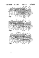
- FIG. 1 is a view in axial half-section of the female element alone, that is the element on the feed side.
- FIG. 2 is a view similar to FIG. 1, showing the male element, that is, the element on the side of the use circuit, partly engaged in the female element.
- FIG. 3 is a view similar to FIG. 1 and 2, showing the coupler after coupling these two elements, in the case where there is a residual pressure in the use circuit.
- FIG. 4 is a view similar to FIG. 3, showing the coupler in use position, that is, after opening of the feed circuit.
- FIG. 5 is a view similar to FIG. 4, showing the coupler during the beginning of an uncoupling operation, that is, of withdrawal of the male element in relation to the female element.
- FIG. 6 is a view similar to FIG. 5, showing the two assembled elements of the coupler when the coupling has been done in the absence of residual pressure in the use circuit.
- the coupler according to the invention is of the type with valves and with mobile outer socket, with double action.
- the female element of this coupler as shown in FIG. 1, includes a tubular central body 3, designed to be fixed rigidly to a male or female connection of one element of a distribution circuit, such as a distributor or other similar (circuit), not shown in the drawing.
- This tubular body 3 has, on the side of its coupling end, that is, on the side of its end opposite that provided for its connection to the feed circuit, a bore 3a, forming the female end of this element, and designed to receive, lodge and retain the tine of the male element 12.
- the tubular body 3 has an annular row of holes 4, passing through, each of which has an inner end of smaller diameter than its outer end, is designed to lodge, while retaining, a locking ball 5.
- the balls 5 are normally held in their innermost position radially, that is, supported against the inner end, serving them as seat, of the corresponding hole, by an inner groove 6a, provided for this purpose, in the bore of an outer mobile socket 6, and which is normally held in the position in which it surrounds the balls 5, by a spiral spring 7, acting simultaneously on the shoulders made for this purpose, on the ends of two annular chambers 8 and 9, made in the bore of the socket 6 and at the periphery of the tubular body 3.
- An axial movement in one direction or the other of the outer mobile socket 6 permits displacing the groove 6a in relation to the row of balls 5, and freeing these latter from any radial constraint, which of course, allows their radial movement toward the outside.
- the tubular element 3 has also, at the inner end of the bore, provided to receive the tip of the male element 12, an inner annular projection 13, of which the surface 13a, opposite the bore 3a, is inclined to serve as seat for the valve 14, associated with the female element 2, and which is normally held in the closing position by a spiral pull-back spring 15, supported, on the one hand, against the bottom 16a of a bore 16 made in the stem 14a of the valve 14, and coaxially with this stem, and on the other hand, against the bottom 17a of a cylindrical sleeve 17, designed to serve as guide for the stem 14a of the valve 14, and which is fixed, through radial fins, with which it is solid, to the tubular body 3 of the female element.
- this fixing is assured by engagement and gripping of the radially outward ends of the fins 11, between two shoulders 19 and 21, facing each other, of which one, 19, is made in a prolongation 3b beyond the seat 13a of the bore 3a of the tubular body 3, and of which the other, 21, is made in an assembling screw 22, screwed onto the corresponding end of the tubular body 3.
- the stem 14a of the valve 14 has, starting from its head 14b, a first section 14'a, of an outer diameter D1, followed by an extension forming a second section 14"a, of a diameter D2 smaller than the diameter D1 of the first section 14'a, from which it is separated by a shoulder 23.
- a ring 24 On the section 14"a of the stem 14a farthest from the head 14b is mounted a ring 24, sliding axially, of which the outer diameter D3 is greater than the diameter D1 of the section 14'a of the stem 14a of the valve 14.
- This ring 24 of which the length is less than that of the section 14"a of the stem 14a of the valve 14, is held prisoner on the latter by a collar 20, provided at the rear end of the stem 14a of the valve 14, and consists of a circlips (ring clip). The ring 24 is thus mounted axially between the shoulder 23 and the collar 24.
- the ring 24 has a truncated cone section, converging in the direction of the head 14b of the valve 14, and the shoulder 23 has a complementing profile which permits it to fit (espouse) perfectly the truncated cone end 24a of the ring 24.
- the ring 24 has a truncated cone segment 24c, assuring continuity of surface between its rear segment 24b and its truncated cone segment 24a.
- the cylindrical sleeve 17, serving to lodge and guide the stem 14a of the valve 14 has two holes 25, passing through, diametrically opposite and directed perpendicular to its axis. These two holes 25 are designed to allow the passage of two side branches 26a of a spring 26 in catch (hook) form. These two side branches 26a are designed to form a retractable stop of the valve 14, limiting, normally, its opening movement to its normal value, and supported against the section 14"a, of smaller diameter D2 of the stem 14a of the valve 14 just behind the shoulder 23, as shown in FIG. 4.
- the ends of its side branches 26a, engaged on the stem 14a of the valve 14 are bent at right angles to the body of the catch 26, and can thus be applied against the cylindrical outer surface of the sleeve 17.
- This male element includes, in a manner known per se, an annular hollow (throat) 27, designed to receive, after its engagement in the bore 3a of the female element 2, the locking balls 5, the engagement of the male tip 12 being made possible by the movement of the mobile socket 6, in ne direction or the other, until the effacement of its groove 6a, in relation to the annular row of balls 5, as shown in FIG. 2, includes also a valve 28, of which only the head is visible in the drawing, but which is normally applied, by a spring, not shown, resting tightly against its seat 29, made at the end of the bore 31 of the tip of this male element 12.
- the purpose of the coupler of the invention is to permit the coupling of two elements female 2 and male 12, and the proper functioning of this coupling, whether or not a residual pressure exists on the use circuit side, that is, the side of the male element 12 of this coupling.
- the side branches 26a of the spring in catch (hook) form 26, and forming the stop limiting the opening movement of the valve 14 of the female element 2 are, in this normal opening position of this valve 14, situated just behind the shoulder 23 of the stem 14a of the valve 14.
- valve 14 of the female element 2 can make a movement double its course C1, necessary to its normal opening. More precisely, this valve 14 must be able to effect a movement equal to the sum of the normal opening movements of the valves 12 and 28.
- the coupling can be done as shown in FIG. 3, which shows the balls 5 engaged in the throat 27 of the tip of the male element 12, without the valve 28 of this element being raised from its seat 29.
- This coupling is made possible by the retractable nature of the stop of the valve 14, consisting of the branches 26a of the spring in catch (hook) form 26.
- valve 14 of the female element 2 Before the coupling, that is, while all the elements are at rest, the valve 14 of the female element 2 is in closing position and the branches 26a of the catch 26 grip between them the sliding ring 24 of its stem 14a, being supported on the cylindrical segment 24b of the ring 24, of which the rear end is itself supported on the collar 20 of the rear end of the stem 14a of the valve 14.
- the truncated cone segment 24c of the ring 24 provides a solution of continuity (a transition), between this latter and the section 14'a of the stem 14a of the valve 14.
- the male element 12 of the coupler being then locked into this female element 2, it is then possible to open the use circuit, so as to establish the circulation of fluid in the direction of the arrow 32.
- the pressure of fluid penetrating into the female element 2 of this coupler which is, of course, greater than the residual pressure prevailing in the use circuit, will inevitably cause the lifting of the valve 28 and, consequently, the movement of the valves 14 and 28 in the direction of fluid circulation, that is, that shown by arrow 32.
- FIG. 6 shows the principle of operation of this coupler, in the case where, during the coupling of these elements, male 12 and female 2, no residual pressure exists in the use circuit. It is evident that, under these circumstances, the engagement of the tip of the male element 12 in the bore 3a of the female element 2, the two valves 28 and 14 rise mutually until they are in their normal opening position as shown in FIG. 6. Now, at the beginning of this engagement, as FIG. 1 shows, the side branches 26a of the catch 26, supported against the cylindrical segment 24b of the ring 24, tend to retain it in the position which it occupies before the coupling, and this, despite the retreat of the stem 14a of the valve 14, which, by this fact, slides without being pulled into the bore of the ring 24.
- This coupler has the advantage, therefore, of working perfectly, whatever the conditions of use under which the coupling of male and female elements takes place.
Landscapes
- Engineering & Computer Science (AREA)
- General Engineering & Computer Science (AREA)
- Mechanical Engineering (AREA)
- Quick-Acting Or Multi-Walled Pipe Joints (AREA)
- Hydraulic Clutches, Magnetic Clutches, Fluid Clutches, And Fluid Joints (AREA)
- Pens And Brushes (AREA)
Applications Claiming Priority (1)
| Application Number | Priority Date | Filing Date | Title |
|---|---|---|---|
| FR8805712A FR2630524B1 (fr) | 1988-04-20 | 1988-04-20 | Coupleur a clapets a douille exterieure mobile |
Publications (1)
| Publication Number | Publication Date |
|---|---|
| US4974635A true US4974635A (en) | 1990-12-04 |
Family
ID=9365801
Family Applications (1)
| Application Number | Title | Priority Date | Filing Date |
|---|---|---|---|
| US07/345,389 Expired - Lifetime US4974635A (en) | 1988-04-20 | 1989-05-01 | Coupler with spring-locked valves |
Country Status (6)
| Country | Link |
|---|---|
| US (1) | US4974635A (de) |
| EP (1) | EP0338942B1 (de) |
| AT (1) | ATE63375T1 (de) |
| DE (1) | DE68900079D1 (de) |
| ES (1) | ES2022758B3 (de) |
| FR (1) | FR2630524B1 (de) |
Cited By (13)
| Publication number | Priority date | Publication date | Assignee | Title |
|---|---|---|---|---|
| US5664759A (en) * | 1996-02-21 | 1997-09-09 | Aeroquip Corporation | Valved coupling for ultra high purity gas distribution systems |
| EP0862010A1 (de) * | 1997-02-21 | 1998-09-02 | FASTER S.r.l. | Steckkupplung |
| US5810031A (en) * | 1996-02-21 | 1998-09-22 | Aeroquip Corporation | Ultra high purity gas distribution component with integral valved coupling and methods for its use |
| US6029701A (en) * | 1995-09-19 | 2000-02-29 | Parker Hannifin Sa | Quick-connect coupling for pressurized fluid lines |
| US20060151032A1 (en) * | 2003-05-20 | 2006-07-13 | Parker Hannifin Sa | Quick -connect coupling for hydraulic fluid conduits |
| US20060289167A1 (en) * | 2005-06-22 | 2006-12-28 | Surjaatmadja Jim B | Methods and apparatus for multiple fracturing of subterranean formations |
| US20070228313A1 (en) * | 2006-03-29 | 2007-10-04 | Massimo Arosio | Quick coupling |
| US20070235092A1 (en) * | 2006-04-06 | 2007-10-11 | Fastest, Inc. | Latching connectors |
| US20080000637A1 (en) * | 2006-06-29 | 2008-01-03 | Halliburton Energy Services, Inc. | Downhole flow-back control for oil and gas wells by controlling fluid entry |
| US7575024B2 (en) | 2005-11-05 | 2009-08-18 | Snap-Tite Technologies, Inc. | Threaded coupling with flow shutoff |
| US7762279B2 (en) | 2005-11-05 | 2010-07-27 | Snap-Tite Technologies, Inc. | Threaded coupling with flow shutoff |
| WO2014155275A1 (en) | 2013-03-27 | 2014-10-02 | Vulcania S.R.L. | A female terminal for rapid-fit connections |
| WO2016172666A1 (en) * | 2015-04-24 | 2016-10-27 | General Plasma. Inc. | Push-to-connect and pull-to-disconnect quick coupling |
Families Citing this family (4)
| Publication number | Priority date | Publication date | Assignee | Title |
|---|---|---|---|---|
| WO1994013990A1 (en) * | 1992-12-07 | 1994-06-23 | Parker-Hannifin Corporation | Push-to-connect coupler with interlocking three-way valve |
| FR2738896B1 (fr) * | 1995-09-19 | 1998-01-30 | Parker Hannifin Rak Sa | Raccord rapide pour conduites de fluide sous pression |
| FR3048754A1 (fr) * | 2016-03-14 | 2017-09-15 | Staubli Sa Ets | Element de raccord fluidique et raccord fluidique comprenant un tel element |
| CN109114340B (zh) * | 2017-06-26 | 2021-03-23 | 中航光电科技股份有限公司 | 直插式连接器及其插座、连接组件 |
Citations (7)
| Publication number | Priority date | Publication date | Assignee | Title |
|---|---|---|---|---|
| US3477468A (en) * | 1967-02-09 | 1969-11-11 | Larry A Kopaska | Coupling device |
| FR2384196A1 (fr) * | 1977-03-19 | 1978-10-13 | Argus Gmbh | Raccord de couplage a obturation rapide pour conduites hydrauliques |
| DE2854511A1 (de) * | 1978-12-16 | 1980-06-19 | Eckerle Otto Gmbh & Co | Kupplung, insbesondere schlauchkupplung fuer hydraulische oder pneumatische leitungen |
| DE3015601A1 (de) * | 1980-04-23 | 1981-10-29 | Aeroquip GmbH, 3510 Hann Münden | Schnellverschlusskupplung fuer insbesondere hydraulikleitungen |
| US4398561A (en) * | 1981-03-27 | 1983-08-16 | Imperial Clevite Inc. | Quick disconnect coupling with locked valving |
| EP0096649A1 (de) * | 1982-03-25 | 1983-12-21 | Aeroquip AG | Unter Druck und auch drucklos kuppelbare Schnellverschlusskupplung, insbesondere für Hydraulikleitungen |
| EP0184702A2 (de) * | 1984-12-08 | 1986-06-18 | Aeroquip, Zweigniederlassung der Trinova GmbH | Auch bei unter Druck stehendem Stecker kuppelbare Rohrabreisskupplung für Hydraulikleitungen |
-
1988
- 1988-04-20 FR FR8805712A patent/FR2630524B1/fr not_active Expired - Lifetime
-
1989
- 1989-01-31 EP EP89420026A patent/EP0338942B1/de not_active Expired - Lifetime
- 1989-01-31 ES ES89420026T patent/ES2022758B3/es not_active Expired - Lifetime
- 1989-01-31 DE DE8989420026T patent/DE68900079D1/de not_active Expired - Lifetime
- 1989-01-31 AT AT89420026T patent/ATE63375T1/de not_active IP Right Cessation
- 1989-05-01 US US07/345,389 patent/US4974635A/en not_active Expired - Lifetime
Patent Citations (8)
| Publication number | Priority date | Publication date | Assignee | Title |
|---|---|---|---|---|
| US3477468A (en) * | 1967-02-09 | 1969-11-11 | Larry A Kopaska | Coupling device |
| FR2384196A1 (fr) * | 1977-03-19 | 1978-10-13 | Argus Gmbh | Raccord de couplage a obturation rapide pour conduites hydrauliques |
| US4200121A (en) * | 1977-03-19 | 1980-04-29 | Argus Gesellschaft Mbh | Quick-closure coupling for hydraulic lines |
| DE2854511A1 (de) * | 1978-12-16 | 1980-06-19 | Eckerle Otto Gmbh & Co | Kupplung, insbesondere schlauchkupplung fuer hydraulische oder pneumatische leitungen |
| DE3015601A1 (de) * | 1980-04-23 | 1981-10-29 | Aeroquip GmbH, 3510 Hann Münden | Schnellverschlusskupplung fuer insbesondere hydraulikleitungen |
| US4398561A (en) * | 1981-03-27 | 1983-08-16 | Imperial Clevite Inc. | Quick disconnect coupling with locked valving |
| EP0096649A1 (de) * | 1982-03-25 | 1983-12-21 | Aeroquip AG | Unter Druck und auch drucklos kuppelbare Schnellverschlusskupplung, insbesondere für Hydraulikleitungen |
| EP0184702A2 (de) * | 1984-12-08 | 1986-06-18 | Aeroquip, Zweigniederlassung der Trinova GmbH | Auch bei unter Druck stehendem Stecker kuppelbare Rohrabreisskupplung für Hydraulikleitungen |
Cited By (21)
| Publication number | Priority date | Publication date | Assignee | Title |
|---|---|---|---|---|
| US6029701A (en) * | 1995-09-19 | 2000-02-29 | Parker Hannifin Sa | Quick-connect coupling for pressurized fluid lines |
| US5810031A (en) * | 1996-02-21 | 1998-09-22 | Aeroquip Corporation | Ultra high purity gas distribution component with integral valved coupling and methods for its use |
| US5863023A (en) * | 1996-02-21 | 1999-01-26 | Aeroquip Corporation | Valved coupling for ultra high purtiy gas distribution system |
| US5924447A (en) * | 1996-02-21 | 1999-07-20 | Aeroquip Corporation | Ultra high purity gas distribution component with integral valved coupling and methods for its use |
| US6035609A (en) * | 1996-02-21 | 2000-03-14 | Aeroquip Corporation | Ultra high purity gas distribution component with integral valved coupling and methods for its use |
| US5664759A (en) * | 1996-02-21 | 1997-09-09 | Aeroquip Corporation | Valved coupling for ultra high purity gas distribution systems |
| EP0862010A1 (de) * | 1997-02-21 | 1998-09-02 | FASTER S.r.l. | Steckkupplung |
| US20060151032A1 (en) * | 2003-05-20 | 2006-07-13 | Parker Hannifin Sa | Quick -connect coupling for hydraulic fluid conduits |
| US7168449B2 (en) * | 2003-05-20 | 2007-01-30 | Parker Hannifin Sa | Quick coupling for hydraulic fluid pipes |
| US7431090B2 (en) | 2005-06-22 | 2008-10-07 | Halliburton Energy Services, Inc. | Methods and apparatus for multiple fracturing of subterranean formations |
| US20060289167A1 (en) * | 2005-06-22 | 2006-12-28 | Surjaatmadja Jim B | Methods and apparatus for multiple fracturing of subterranean formations |
| US7762279B2 (en) | 2005-11-05 | 2010-07-27 | Snap-Tite Technologies, Inc. | Threaded coupling with flow shutoff |
| US7575024B2 (en) | 2005-11-05 | 2009-08-18 | Snap-Tite Technologies, Inc. | Threaded coupling with flow shutoff |
| US20070228313A1 (en) * | 2006-03-29 | 2007-10-04 | Massimo Arosio | Quick coupling |
| US7815169B2 (en) * | 2006-03-29 | 2010-10-19 | Faster S.P.A. | Quick coupling |
| US20070235092A1 (en) * | 2006-04-06 | 2007-10-11 | Fastest, Inc. | Latching connectors |
| US8056581B2 (en) * | 2006-04-06 | 2011-11-15 | Fastest, Inc. | Latching connectors |
| US20080000637A1 (en) * | 2006-06-29 | 2008-01-03 | Halliburton Energy Services, Inc. | Downhole flow-back control for oil and gas wells by controlling fluid entry |
| WO2014155275A1 (en) | 2013-03-27 | 2014-10-02 | Vulcania S.R.L. | A female terminal for rapid-fit connections |
| WO2016172666A1 (en) * | 2015-04-24 | 2016-10-27 | General Plasma. Inc. | Push-to-connect and pull-to-disconnect quick coupling |
| US10989343B2 (en) | 2015-04-24 | 2021-04-27 | General Plasma Inc. | Push-to-connect and pull-to-disconnect quick coupling |
Also Published As
| Publication number | Publication date |
|---|---|
| ATE63375T1 (de) | 1991-05-15 |
| FR2630524B1 (fr) | 1990-08-03 |
| EP0338942A1 (de) | 1989-10-25 |
| ES2022758B3 (es) | 1991-12-01 |
| EP0338942B1 (de) | 1991-05-08 |
| FR2630524A1 (fr) | 1989-10-27 |
| DE68900079D1 (de) | 1991-06-13 |
Similar Documents
| Publication | Publication Date | Title |
|---|---|---|
| US4974635A (en) | Coupler with spring-locked valves | |
| US6257278B1 (en) | High pressure fluidline connector | |
| EP0995063B1 (de) | Kupplungsverriegelung | |
| EP1666783B1 (de) | Rohrverbindung und muffe für rohrverbindung | |
| US2708589A (en) | Tension actuated pipe coupling | |
| US6511100B1 (en) | Ball-bearing coupler | |
| US8256803B2 (en) | Socket for pipe joint and pipe joint | |
| US3120968A (en) | Quick disconnect coupling with ring detent | |
| US5390963A (en) | Tube coupler | |
| US4404714A (en) | Coupling mechanism | |
| US2503495A (en) | Coupling | |
| US2631872A (en) | Quick coupling | |
| US6886803B2 (en) | Female and male couplers of pipe coupling | |
| US6983958B2 (en) | Supply connection device for a fluid pressure system | |
| JP4831619B2 (ja) | 継手、この継手に用いるソケット及びプラグ | |
| US8469406B2 (en) | Socket for pipe joint and pipe joint | |
| US5873386A (en) | Quick-release coupling | |
| US4645373A (en) | Quick release connectors | |
| US3477688A (en) | Fluid line coupling | |
| GB2254073A (en) | Connecting a specimen sampling bottle to a supplying pipe. | |
| US4216982A (en) | Speed slip-on hose coupler | |
| US6027097A (en) | Water stop hose connector | |
| JPS6334355B2 (de) | ||
| US4792162A (en) | Protective device for quick connect coupling | |
| US3666300A (en) | Quick disconnect coupling |
Legal Events
| Date | Code | Title | Description |
|---|---|---|---|
| AS | Assignment |
Owner name: PARKER HANNIFIN RAK, ZONE INDUSTRIELLE DU MONT-BLA Free format text: ASSIGNMENT OF ASSIGNORS INTEREST.;ASSIGNORS:HANUS, JEAN-NIOLAS;ANTHOINE, BERNARD;REEL/FRAME:005135/0036 Effective date: 19890831 |
|
| STCF | Information on status: patent grant |
Free format text: PATENTED CASE |
|
| FEPP | Fee payment procedure |
Free format text: PAYOR NUMBER ASSIGNED (ORIGINAL EVENT CODE: ASPN); ENTITY STATUS OF PATENT OWNER: LARGE ENTITY |
|
| FPAY | Fee payment |
Year of fee payment: 4 |
|
| AS | Assignment |
Owner name: PARKER HANNIFIN S.A., FRANCE Free format text: CHANGE OF NAME;ASSIGNOR:PARKER HANNIFIN RAK S.A.;REEL/FRAME:008761/0794 Effective date: 19970131 |
|
| FPAY | Fee payment |
Year of fee payment: 8 |
|
| FPAY | Fee payment |
Year of fee payment: 12 |