US4971306A - Seals for cylindrical surfaces - Google Patents

Seals for cylindrical surfaces Download PDF

Info

Publication number
US4971306A
US4971306A US07/270,881 US27088188A US4971306A US 4971306 A US4971306 A US 4971306A US 27088188 A US27088188 A US 27088188A US 4971306 A US4971306 A US 4971306A
Authority
US
United States
Prior art keywords
indentations
cylindrical surface
seal
shaft
shaft means
Prior art date
Legal status (The legal status is an assumption and is not a legal conclusion. Google has not performed a legal analysis and makes no representation as to the accuracy of the status listed.)
Expired - Lifetime
Application number
US07/270,881
Inventor
Takeshi Jinnouchi
Hirochi Matsumoto
Tetsuya Iguchi
Current Assignee (The listed assignees may be inaccurate. Google has not performed a legal analysis and makes no representation or warranty as to the accuracy of the list.)
Eagle Industry Co Ltd
Original Assignee
Eagle Industry Co Ltd
Priority date (The priority date is an assumption and is not a legal conclusion. Google has not performed a legal analysis and makes no representation as to the accuracy of the date listed.)
Filing date
Publication date
Priority claimed from JP63030817A external-priority patent/JP2662720B2/en
Application filed by Eagle Industry Co Ltd filed Critical Eagle Industry Co Ltd
Assigned to EAGLE INDUSTRY CO., LTD., A CORP. OF JAPAN reassignment EAGLE INDUSTRY CO., LTD., A CORP. OF JAPAN ASSIGNMENT OF ASSIGNORS INTEREST. Assignors: IGUCHI, TETSUYA, JINNOUCHI, TAKESHI, MATSUMOTO, HIROSHI
Application granted granted Critical
Publication of US4971306A publication Critical patent/US4971306A/en
Anticipated expiration legal-status Critical
Expired - Lifetime legal-status Critical Current

Links

Images

Classifications

    • FMECHANICAL ENGINEERING; LIGHTING; HEATING; WEAPONS; BLASTING
    • F01MACHINES OR ENGINES IN GENERAL; ENGINE PLANTS IN GENERAL; STEAM ENGINES
    • F01DNON-POSITIVE DISPLACEMENT MACHINES OR ENGINES, e.g. STEAM TURBINES
    • F01D11/00Preventing or minimising internal leakage of working-fluid, e.g. between stages
    • F01D11/003Preventing or minimising internal leakage of working-fluid, e.g. between stages by packing rings; Mechanical seals
    • FMECHANICAL ENGINEERING; LIGHTING; HEATING; WEAPONS; BLASTING
    • F16ENGINEERING ELEMENTS AND UNITS; GENERAL MEASURES FOR PRODUCING AND MAINTAINING EFFECTIVE FUNCTIONING OF MACHINES OR INSTALLATIONS; THERMAL INSULATION IN GENERAL
    • F16JPISTONS; CYLINDERS; SEALINGS
    • F16J15/00Sealings
    • F16J15/16Sealings between relatively-moving surfaces
    • F16J15/26Sealings between relatively-moving surfaces with stuffing-boxes for rigid sealing rings
    • FMECHANICAL ENGINEERING; LIGHTING; HEATING; WEAPONS; BLASTING
    • F16ENGINEERING ELEMENTS AND UNITS; GENERAL MEASURES FOR PRODUCING AND MAINTAINING EFFECTIVE FUNCTIONING OF MACHINES OR INSTALLATIONS; THERMAL INSULATION IN GENERAL
    • F16JPISTONS; CYLINDERS; SEALINGS
    • F16J15/00Sealings
    • F16J15/44Free-space packings
    • F16J15/441Free-space packings with floating ring
    • F16J15/442Free-space packings with floating ring segmented
    • FMECHANICAL ENGINEERING; LIGHTING; HEATING; WEAPONS; BLASTING
    • F05INDEXING SCHEMES RELATING TO ENGINES OR PUMPS IN VARIOUS SUBCLASSES OF CLASSES F01-F04
    • F05DINDEXING SCHEME FOR ASPECTS RELATING TO NON-POSITIVE-DISPLACEMENT MACHINES OR ENGINES, GAS-TURBINES OR JET-PROPULSION PLANTS
    • F05D2250/00Geometry
    • F05D2250/20Three-dimensional
    • F05D2250/23Three-dimensional prismatic
    • F05D2250/231Three-dimensional prismatic cylindrical
    • YGENERAL TAGGING OF NEW TECHNOLOGICAL DEVELOPMENTS; GENERAL TAGGING OF CROSS-SECTIONAL TECHNOLOGIES SPANNING OVER SEVERAL SECTIONS OF THE IPC; TECHNICAL SUBJECTS COVERED BY FORMER USPC CROSS-REFERENCE ART COLLECTIONS [XRACs] AND DIGESTS
    • Y02TECHNOLOGIES OR APPLICATIONS FOR MITIGATION OR ADAPTATION AGAINST CLIMATE CHANGE
    • Y02TCLIMATE CHANGE MITIGATION TECHNOLOGIES RELATED TO TRANSPORTATION
    • Y02T50/00Aeronautics or air transport
    • Y02T50/60Efficient propulsion technologies, e.g. for aircraft

Abstract

A shaft seal for sealing fluids includes a rotating shaft means having an axis and an external cylindrical surface. A seal ring is disposed about the shaft and has an internal cylindrical surface juxtaposed to the external cylindrical surface and mating therewith to form mating cylindrical surfaces. One of the cylindrical surfaces is a smooth cylindrical surface, and a plurality of spaced, generally parallel indentations are formed in the smooth cylindrical surface, the indentations extending at an acute angle relative to the axial direction of the shaft such that fluid entering the mating cylindrical surfaces is returned by the indentations as the shaft rotates.

Description

BACKGROUND OF THE INVENTION
The present invention relates to a seal for a cylindrical surface which is used as a shaft seal devices.
One example of the seal of this kind has been heretofore known as shown in FIGS. 18 to 20, wherein a segment seal 1 is brought into sliding contact with a liner 14 on the side of a shaft 11.
More specifically, this segment seal 1 has a housing 2 which houses therein a seal element (seal ring kit 3) comprising the combination of a seal ring 4, a cover ring 5, a key 6, an extension spring (garter spring 7) and a compression spring (coil spring 8), which is covered with a spring retainer (spring adapter 9) and fixed by a snap ring 10. The seal ring 4 and the cover ring 5 are principally formed of a carbon material, and both the rings 4 and 5 are equally divided into more than two sections depending on the size of a shaft 11, which are combined with the divisional phase deviated in the circumferential direction. A divisional portion of the seal ring 4 is formed into a step joint 12 in order to prevent leakage in an axial direction. The seal element 3 is stopped in rotation through the key 6 by means of a rotation lock pin 13 disposed upright on the housing 2, and held on the shaft 11 by means of the extension spring 7 so as to be able to follow the radial movement of the shaft 11. The internal diameter surface of the seal ring 4 comes into sliding contact with the external diameter surface of a liner 14 slipped over the shaft 11 to constitute a sliding seal portion (a dynamic seal portion 15) which forms a primary seal portion. The seal element 3 is axially biased by the compression spring 8, and the perpendicular end thereof is pressed against the end wall of the housing 2 to constitute a static seal portion 16 which forms a secondary seal portion. The aforesaid internal diameter surface and perpendicular end which form both the seal portions 15 and 16, respectively, are formed with pressure balance grooves 17 and 18 to relieve loads resulting from fluid pressures. FIG. 21 shows one example of the pressure balance groove 17 formed in the internal diameter surface. The liner 14 in sliding contact with the internal diameter surface of the seal ring 4 is generally formed of hardened steel, and the external diameter surface is finished into a flat surface.
The segment seal 1 constructed as described above is used to seal various fluids. However, in the case where a gas G is sealed by this segment seal 1, a sliding seal portion 15 operates under a dry condition, and therefore the resulting from sliding cannot be sometimes removed efficiently. To cope with this situation, in the segment seal 1, the internal diameter surface of the seal ring 4 is formed in advance with the pressure balance groove 17 to positively introduce gas pressure therein to keep the seal surface pressure lower so as to prevent the heat result from sliding from exceeding a level above a limit value. However, when a differential pressure between both sides of the seal exceeds a level above the functional limit of the lowering the surface pressure caused by the pressure balance groove 17 or when the number of revolutions of the shaft increases, sliding heat in excess of the heat limit of the sliding material occurs. Under the condition as described in excess of the heat limit, liquids (cooling liquids) such as oil or water are sprayed by a jet against the shaft portion in the vicinity of the sliding seal portion 15 on the low pressure side to cool the sliding seal portion 15.
Further, in jet engines for aircraft, gas compressors or gas turbines, etc., high pressure gas such as compressed air, combustion gas and the like flow into bearing portions failing to properly lubricate the bearings. Therefore, it becomes necessary to provide a seal with a partition between a bearing chamber and a high pressure gas portion, and the segment seal 1 is used for that partitioning portion. FIG. 22 shows a construction of a bearing chamber 19 and peripheral portions thereof of a jet engine on which the segment seal 1 is mounted for the reason as described above. The segment seals 1 are mounted on both axial sides so as to isolate the bearing chamber 19. Oil for lubrication and cooling of a bearing 20 is supplied by jets 21 and 22 into the bearing chamber 19, the oil also having a function to cool the segment seal 1.
As described above, the segment seal 1 is incorporated into a variety of devices to seal gas, and the segment seal 1 is sometimes used under the situation that in the working atmosphere, the front receives high pressure gas and the back receives low pressure liquid, as described above. Under these circumstances, when the pressure difference between the gas and liquid is small, the liquid enters the sliding seal portion 15 and the liquid sometimes further leaks into the gas side.
The phenomenon wherein when the pressure difference is small, the low pressure liquid leaks into the high pressure gas side is explained as follows:
The case of the aforementioned jet engine is here taken as an example. Oil O in the form of mists for lubrication and cooling of the bearing 20 and cooling of the sliding seal portion 15 is present on the low pressure side of the segment seal 1, and the seal 1 is in an atmosphere wherein the oil O leaks, and the oil O also enters the seal element 3. When the pressure difference between the gas G and the oil O is large, the gas pressure overcomes the surface tension of the oil O and enters a clearance of the seal element 3 to prevent further entry of the oil O, whereas when the pressure difference becomes low, particularly, less than 0.3 kgf/cm2, the surface tension of the oil O becomes greater than the gas pressure so that the oil O enters even the interior of the seal element 3, which has been experimentally understood. Particularly, in the segment seal 1, the leakage of the gas G is concentrated on the divisional portion of the seal element 3 in terms of the divisional construction of the seal element 3, and therefore in the circumferential seal portion (sliding seal portion 15 and static seal portion 16) other than the divisional portion, leakage of the gas G is extremely small, and the oil O is liable to enter that portion. In addition, in the sliding seal portion 15 in sliding contact with the liner 14, oscillations resulting from the rotation of the shaft 11 occur, and therefore, a variation in surface pressure occurs in the sliding seal portion 15 in terms of the following operation with respect to the oscillations of the seal element 3, as a result of which the state of the oil film of the entered oil O tends to change. Furthermore, in the sliding seal portion 15, the seal ring 4 assumes a state wherein the seal ring 4 is levitated from the liner 14 (just like the state wherein a surfboard rides on the waves) due to the oil film formed on the portion 15 to further promote an entry of the oil O and a formation of an oil film. The oil film formed on the sliding portion 15 is scraped at the divisional portion of the seal ring 4 as the shaft 11 rotates and leaks into the gas G side.
In the prior art, it is considered that in order to effectively operate the segment seal 1 under the condition of low pressure difference as described above, two opposed seal elements 3 are used, as shown in FIG. 23, to feed high pressure gas (air or the like is suitable) into an intermediate chamber 23 to intentionally create the condition of a high pressure difference. However, in this case, a space to some extent is required and the construction is complicated, which is not an adequate measure. Alternatively, if this measure is used on a jet engine, the high pressure gas is bled from the compressor portion of the engine, resulting in a complex engine construction of the engine and the lowering in efficiency caused by bleeding.
SUMMARY OF THE INVENTION
In view of the foregoing, it is an object of the present invention to provide a construction which is designed so that even when a pressure difference between gas and liquid is small and when no pressure difference is present, the entry of liquid into the gas side can be minimized, and which can be widely applied not only to segment seals but also to seals for cylindrical surfaces.
For achieving the aforesaid object, the present invention provides a seal characterized in that an internal diameter seal surface of the seal member on the fixed side in direct contact with the seal member on the rotational side or an external diameter seal surface of the seal member on the rotational side in direct contact with the seal member on the fixed side is formed with a number of inclined grooves or stripes. In the segment seal, the seal member on the fixed side comprises seal rings which are divided into plural sections in the circumferential direction, and the seal member on the rotational side comprises a liner on the shaft side in terms of the relationship between the segment seal and the liner.
In the seal according to the present invention, liquids entering the sliding seal portion formed between the seal member on the rotational side and the seal member on the fixed side can be discharged toward the liquid side by the viscosity of such liquids and by the pumping action of a number of grooves or stripes formed in the seal member on the fixed side or on the rotational side, to prevent such liquids from leakage.
While the outline of the present invention has been described simply, other objects and new features of the present invention will be completely apparent from reading the ensuing detailed description in conjunction with the embodiments shown in the accompanying drawing. It is to be noted however that the drawings merely show one embodiment for describing the present invention and the technical scope of the present invention is not limited thereby.
BRIEF DESCRIPTION OF THE DRAWINGS
FIGS. 1, 4, 8 and 11 are sectional views, respectively, showing the state wherein a segment seal according to the present invention is mounted;
FIGS. 2, 3, 5, 6, 7, 9 and 10 are developed views, respectively, showing essential parts of an internal diameter surface of a seal ring according to the present invention;
FIG. 12 is a graph showing the results of performance experiments;
FIGS. 13 to 17 are sectional views, respectively, showing the state wherein a seal according to the present invention is mounted and developed views, respectively, showing essential parts of an external diameter surface of a liner;
FIG. 18 is a partly cutaway exploded perspective view of a segment seal according to prior art;
FIGS. 19, 20, 22, 23 and 24 are sectional views, respectively, showing the state wherein a seal according to prior art is mounted; and
FIG. 21 is a developed view showing essential parts of an internal diameter surface of a seal ring according to prior art.
DESCRIPTION OF THE PREFERED EMBODIMENTS
Embodiments of the present invention will be described hereinafter with reference to the accompanying drawings.
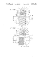
FIG. 1 depicts a section showing the state wherein a segment seal 24 corresponding to that shown in FIG. 19 of the prior art is mounted. As will be apparent from a comparison between these Figures, in the segment seal 24 according to this embodiment, a pressure balance groove 17 is not formed in an internal diameter seal surface 25 of a seal ring 4 constituting a seal element 3 but the entire surface of the internal diameter seal surface 25 is placed in close contact with the liner 14 to form a sliding seal portion 15, which is formed with a number of elongated indentations 26 as shown in FIG. 2. That is, the segment seal 24 is mounted so as to partition a high pressure gas G from a low pressure liquid L and is constructed on the assumption that it is used under the condition that a pressure difference between the gas G and the liquid L is small. In the case where the pressure difference is small as described and more specifically the pressure difference is less than 0.3 kgf/cm2, the internal diameter of the seal ring 4 can be sufficiently applied as a flat type which has no pressure balance groove 17. Conversely, when the pressure balance groove 17 is present, the liquid L entered the sliding seal portion 15 is scraped by a dam portion of the pressure balance groove 17 to further promote the entry of the liquid L. In addition, in the arrangement wherein the pressure balance groove 17 is eliminated to provide a simple flat surface, the seal ring 4 is levitated as in the phenomenon in which a surfboard rides on the wave, failing to prevent the entry of the liquid L. In view of the foregoing, the segment seal 24 is designed so that an internal diameter surface 25 formed into a flat configuration is formed with the indentations 26 so as to return the liquid L entered the sliding seal portion 15 by making use of the rotational peripheral speed of the shaft 11.
FIG. 2 shows the internal diameter seal surface 25 in a developed form, in which the high pressure gas G and the low pressure liquid L are positioned on the right-hand and left-hand, respectively, as viewed in the Figure. The rotational direction relative to the liner 14 as the shaft 11 rotates is indicated by arrow A in the Figure. The indentations 26 are formed so as to reach the edge 27 on the liquid side of the internal diameter seal surface 25 but not to reach the edge 28 on the gas side, and the indentations 26 are formed while being inclined at an angle of 0°<θ<90° in the rotational direction A starting at a portion formed at the edge 27 on the liquid side. FIG. 3 shows an example in which the indentations 26 are widened to form grooves 29. It is noted that in FIGS. 2 and 3, the indentations 26 or grooves 29 are not provided in step joints 12.
The arrangement wherein the segment seal 24 is mounted on the bearing 20 portion of a jet engine shown in FIG. 23 is as shown in FIG. 4. As will be apparent from a comparison between both the Figures, according to the segment seal 24, the construction can be simplified and the occupying space can be considerably reduced. A mounting position of a fan (not shown) arranged on the left side as viewed in the Figure can be made closer to the bearing 20. The device can be light-weight as a whole, and at the same time, bleeding from the compressor portion is not required thus enhancing the efficiency of the engine.
FIGS. 5 to 7 show a type which can be utilized when the pressure difference between the gas G and the liquid L is larger to some extent as compared with the situation in the case of the above-described two examples (FIGS. 2 and 3). In FIGS. 5 to 7 both the indentations 26 in FIGS. 5 and 6 and the grooves 29 in FIG. 7 for discharging the liquid are provided and the grooves 30 in FIGS. 5 and 7 and indentations 31 in FIG. 6 are provided for the pressure balance.
It is contemplated that in the case where the pressure difference between the gas G and the liquid L is further large, the segment seal 24 according to the present invention with the indentations 26 or grooves 29 for discharging the liquid and the segment seal 1 of the conventional type are arranged. This construction is particularly effective where during the operation, the liquid L causes the seal portion 15 to be wetted and during the stoppage or at the time of start, the liquid L enters the seal portion 15. That is, in the case where the pressure difference is large during high speed rotation, the sliding heat of the seal portion 15 increases accordingly. Therefore, when the seal portion 15 is wetted by the liquid L, the liquid L, particularly the oil O, becomes thermally decomposed due to the heat generation during the high speed operation to produce sludge, and the oil O is carbonized or caulked to materially deteriorate the operability of the seal or to lose the sealing function as the case may be. On the other hand, in the FIG. 8 construction, the segment seal 24 of the present invention is arranged on the liquid L side, and the segment seal 1 of the conventional type on the gas G side is operated under a dry condition, thus eliminating a liquid leakage of the seal 1. In the segment seal 24 of the present invention having the aforesaid construction, the indentations 26 or grooves 29 are formed to extend through the axial length as shown in FIGS. 9 and 10. In FIG. 8, reference numeral 32 designates a vent hole bored in a chamber 33 between both the segment seals 1 and 24. More specifically, the vent hole 32 is provided to vent the gas G leaked from the segment seal 1 on the high pressure side, and machined in a direction at which the liquid L is difficult to flow in. Any number of such vent holes 32 can be provided in the circumferential direction, and particularly the vent hole 32 provided at the lower side of the chamber 33 can also function as a drain hole for the liquid L.
The above-described construction can be applied not only to the segment seal of the 2-ring type so far described but to a segment seal of the 1-ring type without the cover ring 5 and to a segment seal of the 3-ring type also serving as a back ring. FIG. 24 shows one example of a segment seal 34 of the 3-ring type according to the prior art, in which the seal ring 4 and the back ring 35 are formed in their internal diameter surfaces with pressure balance grooves 17 and 36. On the other hand, a segment seal 37 of the same type as that previously mentioned according to the present invention is not provided with pressure balance grooves but has an internal diameter surface 25 of the seal ring 4 formed with the indentations 28 or grooves 29 for discharging the liquid so far described, as shown in FIG. 11.
FIG. 12 is a graph showing the results of performance experiments conducted on the segment seal 24 according to the present invention in which the indentations 26 shown in FIGS. 2 and 9 are formed in the internal diameter seal surface 25 of the seal ring 4. The experiments was carried out in the following procedure:
______________________________________                                    
Size of seal:   Φ250 mm                                               
Oil:            Lubricating oil for aircraft (60° C.)              
Roundness of liner:                                                       
                0.015 mm (elliptical shape)                               
Pressure difference:                                                      
                none                                                      
Temperature:    Normal temperature                                        
Width of indentations:                                                    
                0.2 mm                                                    
Depth of indentations:                                                    
                0.1 mm                                                    
Inclined angle  15°                                                
of indentations (θ)                                                 
Pitch of indentations:                                                    
                6 mm                                                      
 • Plot:  FIG. 2 type                                               
 ⊚ Plot:                                                   
                FIG. 9 type                                               
.increment.Plot:                                                          
                Flat face type                                            
______________________________________                                    
COMPARATIVE EXAMPLE
The results showed that the segment seal 24 according to the present invention remarkably reduced oil leakage as compared with the seal of the flat face type as a comparative example. This experiment was conducted under the condition close to the peripheral speed of the rotational shaft of the front fan of an aircraft engine and under the condition close to practical use since the pressure of the fan portion rarely occurs. As the result of the experiments, the effect for the liner 14 slightly modified was also confirmed. Furthermore, it has been confirmed as the result of other experiments that the depth of the indentations 26 or grooves 29 is preferably less than approximately 0.5 mm (approximately 0.02 inch).
An example in which the characteristic construction of the present invention is applied to a rotational member will be described hereinafter.
FIG. 13 depicts the mounting state of a segment seal 38 corresponding to FIG. 19 according to the above-described prior art. An external diameter surface 39 of the liner 14 in sliding contact with an internal diameter surface 25 of the seal ring 4 of the segment seal 38 is formed with a number of indentations 26. The indentations 26 can be processed when the external diameter surface 39 of the liner 14 is surface-finished. In case of turning-finish, the indentations 26 are of a single continuous form as shown in FIG. 13, and in case of grinding-finish, they are of a discontinuous form as shown in FIG. 14. The indentations 26 can be replaced by grooves 29 having greater widths but if the grooves 29 are employed as shown in FIG. 15, the depth thereof need be smaller than that of the indentations 26.
In these FIGS. 13 to 15, the shaft 11 and the liner 14 slipped thereover are to be rotated counterclockwise as viewed in the direction of B, and the indentations 26 or grooves 29 are inclined in the direction as shown so as to push back the liquid L by the pumping action thereof, the angle θ inclined with respect to the axis thereof being set to 30°<θ<90°, and the depth being set to 0.25 mm (0.01 inch) or less.
In FIGS. 13 to 15, the indentations 26 or grooves 29 are formed in the entire external diameter surface of the liner 14. That is, they are formed to extend through the axial length of the sliding seal portion 15 but the indentations 26 or grooves 29 are very finely formed and therefore, leaking of the gas G toward the liquid L through the indentations 26 or grooves 29 can be ignored in a sense of quantity. To stop the leakage of the gas G, a non-processed zone 40 of the indentations 26 or grooves 29 may be provided in the edge on the gas side of the sliding seal portion 15 as shown in FIG. 16. Preferably, the width W of the non-processed zone 28 is more than 0.5 mm.
In FIGS. 13 to 15, the internal diameter surface 25 of the seal ring 4 in sliding contact with the external diameter surface 39 of the liner 14 formed with the indentations 26 or grooves 29 is formed with pressure balance grooves 17 as illustrated in FIG. 21. Accordingly, the external diameter surface 39 of the liner 14 merely comes into sliding contact with the seal dam portion other than those formed with the pressure balance grooves 17 out of the internal diameter surface 25 of the seal ring 4, but even with such a construction, the indentations 26 or grooves 29 can sufficiently perform their function. However, as shown in FIG. 16, the internal diameter surface 25 of the seal ring 4 is not formed with the pressure balance grooves 17 but the internal diameter surface 25 is formed into a flat configuration and brought with overall contact with the external diameter surface 39 of the liner 14, which will no doubt enhance the function of the indentations 26 or grooves 29. Therefore, preferably, the internal diameter surface 25 of the seal ring 4 is formed with the pressure balance grooves 17 if necessary. As shown in FIG. 17, it is considered that the internal diameter surface 25 of the seal ring 4 is formed into a flat configuration and the indentations 26 or grooves 29 are adjusted to the external diameter surface 39 of the liner 14 to form the pressure balance grooves 30.
When the present seal is mounted on the bearing portion 20 of a jet engine shown in FIG. 23, the state thereof assumes to the state similar to that previously shown in FIG. 4. As will be apparent from a comparison between both the Figures, according to the present seal, the construction can be simplified and the occupying space can be considerably reduced. The mounting position of a fan (not shown) arranged on the left side as viewed in the Figure can be made closer to the bearing 20. The device can be light-weight as a whole and at the same time, bleeding from the compressor portion is not required thus enhancing the efficiency of the engine.
In the case where the device of the present invention is used for machinery in which the pressure of the gas G increases with the result that the pressure difference between the gas G and the liquid L further increases, it is considered that the seal construction of the present invention comprising a combination of the liner 14 with the external diameter surface 39 formed with the liquid discharging indentations 26 or grooves 29 and the seal ring 4 with the internal diameter surface 25 formed into a flat configuration and the conventional type segment seal construction may be arranged. This construction is particularly effective in the case where during the operation, the liquid L causes the seal portion 15 to be wetted, and during the stoppage or at the time of start, the liquid L enters the seal portion 15. Namely, for example, in the compressor, where the pressure of the liquid L during high speed operation is high, the sliding heat of the seal portion 15 increases accordingly. Therefore, when the seal portion 15 is in the state wetted by the liquid L, particularly the oil O becomes heat decomposed to produce sludge, and the oil O is carbonized or caulked to materially lower the operability of the seal and lose the sealing function as the case may be. On the other hand, in the present construction, the seal construction of the present invention is arranged on the liquid L side and the conventional type segment seal construction is operated under the dry condition. With this, a liquid leak can be eliminated in the seal.
The above-described construction can be applied, other than a 2-ring type segment seal so far described, to the 1-ring type segment seal without the cover ring 5, and a 3-ring type segment seal provided with a back ring.
Furthermore, generally, formation of the external diameter surface 39 of the liner 14 made of hardened steel with the indentations 26 or grooves 27 is extremely easily processed as compared with the case of formation of the internal diameter surface 25 of the seal ring 4 made of carbon with the indentations or grooves. In addition, particularly in the processing of indentations and finish-processed portions, it is possible to obtain high precision easily by the machining feed (similar to the feed of machining threads) during the machining of parts, which results in extremely high utility for practical use.
While a description has been made of the preferred embodiments of the present invention, it is to be noted that various modification can be made in the present invention without departing form the principle thereof. It is therefore desired that all the modifications by which the advantageous effects of the present invention are substantially obtained through the use of the structure substantially identical or corresponding thereto be included in the scope of the present invention.

Claims (8)

What is claimed is:
1. A shaft seal for sealing fluids comprising a rotating shaft means having an axis and an external cylindrical surface, a seal ring disposed about said shaft means, said seal ring having an internal cylindrical surface juxtaposed to said external cylindrical surface and mating therewith to form mating cylindrical surfaces, one of said cylindrical surfaces being a smooth cylindrical surface, a plurality of spaced, generally parallel indentations formed in said smooth cylindrical surface, said indentations extending at an acute angle relative to the axial direction of said shaft means such that fluid entering said mating cylindrical surfaces is returned by said indentations as said shaft means rotates, said one cylindrical surface having two spaced longitudinal ends, said indentations extending to one of said longitudinal ends of said one cylindrical surface, a plurality of spaced and generally parallel grooves in said one cylindrical surface, said grooves being wider than said indentations, said grooves being generally parallel to said indentations and being disposed in alternating relationship with said indentations.
2. A shaft seal according to claim 1, wherein said grooves terminate short of said one longitudinal end of said one cylindrical surface and extend to the other longitudinal end of said one cylindrical surface.
3. A shaft seal for sealing fluids comprising a rotating shaft means having an axis and an external cylindrical surface, a seal ring disposed about said shaft means, said seal ring having an internal cylindrical surface juxtaposed to said external cylindrical surface and mating therewith to form mating cylindrical surfaces, one of said cylindrical surfaces being a smooth cylindrical surface, a plurality of spaced, generally parallel indentations formed in said smooth cylindrical surface, said indentations extending at an acute angle relative to the axial direction of said shaft means such that fluid entering said mating cylindrical surfaces is returned by said indentations as said shaft means rotates, said one cylindrical surface having two spaced longitudinal ends, said indentations extending to one of said longitudinal ends of said one cylindrical surface, said indentations being designated first indentations, further comprising a plurality of spaced, generally parallel second indentations being parallel to said first indentations and being disposed in alternating relationship relative to said first indentations, said second indentations terminating short of said one longitudinal end of said one cylindrical surface and extending to the other longitudinal end of said one cylindrical surface.
4. A shaft seal according to claim 3, wherein said first indentations and said second indentations have the same width.
5. A shaft seal according to claim 3, wherein said first indentations and said second indentations have different widths.
6. A shaft seal according to claim 3, wherein the depth of said first indentations is different from the depth of said second indentations.
7. A shaft seal for sealing fluids comprising a rotating shaft means having an axis and an external cylindrical surface, a seal ring disposed about said shaft means, said seal ring having an internal cylindrical surface juxtaposed to said external cylindrical surface and mating therewith to form mating cylindrical surfaces, one of said cylindrical surfaces being a smooth cylindrical surface, a plurality of spaced, generally parallel indentations formed in said smooth cylindrical surface, said indentations extending at an acute angle relative to the axial direction of said shaft means such that fluid entering said mating cylindrical surfaces is returned by said indentations as said shaft means rotates, said shaft means comprising a shaft and a liner disposed about said shaft, said indentations being formed on the outer cylindrical surface of said liner, said liner having a greater axial length than the axial length of said mating cylindrical surfaces, said indentations extending to a portion of said liner which extends beyond the longitudinal ends of said mating cylindrical surfaces.
8. A shaft seal for sealing fluids comprising a rotating shaft means having an axis and an external cylindrical surface, a seal ring disposed about said shaft means, said seal ring having an internal cylindrical surface juxtaposed to said external cylindrical surface and mating therewith to form mating cylindrical surfaces, one of said cylindrical surfaces being a smooth cylindrical surface, a plurality of spaced, generally parallel indentations formed in said smooth cylindrical surface, said indentations extending at an acute angle relative to the axial direction of said shaft means such that fluid entering said mating cylindrical surfaces is returned by said indentations as said shaft means rotates, said one cylindrical surface having two spaced longitudinal ends, said indentations extending to one of said longitudinal ends of said one cylindrical surface, some of said indentations extending between both longitudinal ends of said one cylindrical surface, and other of said indentations having terminating ends terminating short of said other longitudinal end of said one cylindrical surface, and further comprising grooves extending between said terminating ends of said other indentations and said other longitudinal ends of said one cylindrical surface, said grooves being wider than said indentations.
US07/270,881 1987-12-25 1988-11-14 Seals for cylindrical surfaces Expired - Lifetime US4971306A (en)

Applications Claiming Priority (4)

Application Number Priority Date Filing Date Title
JP32749987 1987-12-25
JP62-327499 1987-12-25
JP63-30817 1988-02-15
JP63030817A JP2662720B2 (en) 1988-02-15 1988-02-15 Cylindrical face seal

Publications (1)

Publication Number Publication Date
US4971306A true US4971306A (en) 1990-11-20

Family

ID=26369228

Family Applications (1)

Application Number Title Priority Date Filing Date
US07/270,881 Expired - Lifetime US4971306A (en) 1987-12-25 1988-11-14 Seals for cylindrical surfaces

Country Status (4)

Country Link
US (1) US4971306A (en)
DE (1) DE3840487C2 (en)
FR (1) FR2625283A1 (en)
GB (1) GB2214243B (en)

Cited By (20)

* Cited by examiner, † Cited by third party
Publication number Priority date Publication date Assignee Title
US5350181A (en) * 1991-09-30 1994-09-27 Skf Usa Inc. Pumping feature on wear sleeve for unitized seal
US5451066A (en) * 1990-12-19 1995-09-19 Societe Nationale D'etude Et De Construction De Moteurs D'aviation "S.N.E.C.M.A." System for sealing the bearing of a machine, especially a turbomachine
US5496047A (en) * 1992-07-04 1996-03-05 John Crane Uk Limited Mechanical seal containing a sealing face with grooved regions which generate hydrodynamic lift between the sealing faces
EP0872420A1 (en) * 1997-04-15 1998-10-21 Focke &amp; Co. (GmbH &amp; Co.) Lubrification process and sealing arrangement for a packaging machine with folding turret
EP0995933A3 (en) * 1998-10-19 2001-01-31 Stein Seal Company Hydrodynamic lift seal for use with compressible fluids
US6338490B1 (en) * 1998-08-05 2002-01-15 Societe Nationale d'Etude et de Construction de Moteurs d'Aviation “SNECMA” Sealing arrangement with automatic clearance adjustment
DE10039836A1 (en) * 2000-08-16 2002-02-28 Zahnradfabrik Friedrichshafen Ventilation device for automatic motor vehicle transmissions has rectangular sealing rings on shafts, with groove-like ventilation apertures generating pump action
EP1777376A2 (en) 2005-10-18 2007-04-25 United Technologies Corporation Tandem dual element intershaft carbon seal
US20080164658A1 (en) * 2007-01-10 2008-07-10 Do Logan H Slider seal assembly for gas turbine engine
US20090295096A1 (en) * 2008-05-30 2009-12-03 Wood Michael H Cartridge and related methods
CN102155542A (en) * 2011-02-28 2011-08-17 中国北方车辆研究所 Rotary dynamic sealing device
US20110197756A1 (en) * 2010-02-15 2011-08-18 Hoerbiger Kompressortechnik Holding Gmbh Wiper Arrangement and Compressor with such a Wiper Arrangement
US20120223490A1 (en) * 2011-03-02 2012-09-06 Eaton Corporation Segmented seal with axial load control feature
US20130113162A1 (en) * 2006-06-21 2013-05-09 Stein Seal Company Low and Reverse Pressure Application Hydrodynamic Pressurizing Seals
CN104500743A (en) * 2014-12-15 2015-04-08 中国燃气涡轮研究院 Sealing device between reverse-rotating shafts
EP2986832A4 (en) * 2013-04-15 2016-11-09 Stein Seal Co Circumferential back-to-back seal assembly with bifurcated flow
US20200173556A1 (en) * 2018-11-30 2020-06-04 Rolls-Royce Corporation Circumferential air riding carbon seal on ceramic runner
US20200318489A1 (en) * 2019-04-03 2020-10-08 United Technologies Corporation Rotating carbon piston ring seal
US11287043B2 (en) * 2019-08-02 2022-03-29 Kaydon Ring & Seal, Inc. High clearance seal assembly
EP4194722A1 (en) * 2021-12-09 2023-06-14 Raytheon Technologies Corporation Radial lift seal

Families Citing this family (5)

* Cited by examiner, † Cited by third party
Publication number Priority date Publication date Assignee Title
US5039113A (en) * 1990-01-17 1991-08-13 Eg&G Sealol, Inc. Spiral groove gas lubricated seal
DE9011156U1 (en) * 1990-07-28 1990-11-15 Schneider, Friedhelm, 5226 Reichshof, De
DE4136408A1 (en) * 1991-11-05 1993-05-06 Siemens Ag, 8000 Muenchen, De HEAT-MOVABLE ARRANGEMENT FOR SEALING A GAP, IN PARTICULAR FOR STEAM PIPES IN STEAM TURBINES
DE102010042324A1 (en) * 2010-10-12 2012-04-26 Dürr Systems GmbH sealing arrangement
AT510171B1 (en) * 2011-02-17 2012-02-15 Hoerbiger Kompressortech Hold SEALING PACK FOR A ROLLING PISTON ROD OF A PISTON COMPRESSOR

Citations (16)

* Cited by examiner, † Cited by third party
Publication number Priority date Publication date Assignee Title
GB621526A (en) * 1946-12-06 1949-04-11 Angus George Co Ltd Improvements relating to bushes for sealing rotating shafts
US2606779A (en) * 1949-04-07 1952-08-12 Angus George Co Ltd Bush for sealing rotary shafts
US2956824A (en) * 1957-12-27 1960-10-18 Koppers Co Inc Vented shaft seal
US3131942A (en) * 1958-09-15 1964-05-05 Alsacienne Constr Meca Fluid-tight devices for rotating shafts
US3241842A (en) * 1965-03-31 1966-03-22 Gen Electric Sealing means with cooling fluid means
US3482845A (en) * 1965-02-22 1969-12-09 Micus Immobiliar Und Finanzier Oil seal
US3554561A (en) * 1966-09-06 1971-01-12 Gen Motors Corp Unidirectional pumping seal
US3575424A (en) * 1969-11-28 1971-04-20 Koppers Co Inc Pressure balanced circumferential seal assembly
GB1239873A (en) * 1968-07-06 1971-07-21 Richard Heinrich Shaft seal
US3633927A (en) * 1970-02-11 1972-01-11 Federal Mogul Corp Molded-lip hydrodynamic shaft seal
US3973781A (en) * 1972-05-23 1976-08-10 Veb Gummikombinat Berlin Self-lubricating seal
US4082296A (en) * 1976-05-26 1978-04-04 Stein Philip C Seal for sealing between a rotating member and a housing
US4305592A (en) * 1979-10-23 1981-12-15 Transamerica Delaval, Inc. Gas seal bushing
US4407513A (en) * 1977-04-12 1983-10-04 Taiho Kogyo Co., Ltd. Mechanical seal
US4444399A (en) * 1980-11-04 1984-04-24 Eagle Industry Co., Ltd. Mechanical seal and method of forming a sliding surface thereof
US4709930A (en) * 1984-05-19 1987-12-01 Firma Carl Freudenberg Shaft and sealing ring

Family Cites Families (11)

* Cited by examiner, † Cited by third party
Publication number Priority date Publication date Assignee Title
US2860896A (en) * 1953-07-07 1958-11-18 Daimler Benz Ag Means for sealing the gap between a wall and rotary shaft extending therethrough
SE305987B (en) * 1967-01-16 1968-11-11 Forsheda Gummifabrik Ab
US3785660A (en) * 1970-10-15 1974-01-15 Republic Ind Corp Seal
US3801113A (en) * 1971-11-18 1974-04-02 Parker Hannifin Corp Rotary shaft seal
US3874677A (en) * 1973-07-19 1975-04-01 Nasa High speed, self-acting shaft seal
US4118856A (en) * 1974-12-02 1978-10-10 Garlock Inc Bi-directional hydrodynamic shaft seal method
DE2744172A1 (en) * 1976-10-29 1978-05-11 Westinghouse Electric Corp SHAFT SEAL, IN PARTICULAR FOR LARGE COMPRESSOR SHAFTS
JPS6097430A (en) * 1983-11-01 1985-05-31 Meidensha Electric Mfg Co Ltd Method and device for coordinate indication
US4542573A (en) * 1984-09-28 1985-09-24 The Fluorocarbon Company Method of producing a hydrodynamic seal
DE3440797A1 (en) * 1984-11-08 1986-05-07 Fa. Carl Freudenberg, 6940 Weinheim RADIAL SHAFT SEAL
GB2173264B (en) * 1985-04-04 1988-04-27 Aeroquip International Inc Ptfe sealing element for shaft seals

Patent Citations (16)

* Cited by examiner, † Cited by third party
Publication number Priority date Publication date Assignee Title
GB621526A (en) * 1946-12-06 1949-04-11 Angus George Co Ltd Improvements relating to bushes for sealing rotating shafts
US2606779A (en) * 1949-04-07 1952-08-12 Angus George Co Ltd Bush for sealing rotary shafts
US2956824A (en) * 1957-12-27 1960-10-18 Koppers Co Inc Vented shaft seal
US3131942A (en) * 1958-09-15 1964-05-05 Alsacienne Constr Meca Fluid-tight devices for rotating shafts
US3482845A (en) * 1965-02-22 1969-12-09 Micus Immobiliar Und Finanzier Oil seal
US3241842A (en) * 1965-03-31 1966-03-22 Gen Electric Sealing means with cooling fluid means
US3554561A (en) * 1966-09-06 1971-01-12 Gen Motors Corp Unidirectional pumping seal
GB1239873A (en) * 1968-07-06 1971-07-21 Richard Heinrich Shaft seal
US3575424A (en) * 1969-11-28 1971-04-20 Koppers Co Inc Pressure balanced circumferential seal assembly
US3633927A (en) * 1970-02-11 1972-01-11 Federal Mogul Corp Molded-lip hydrodynamic shaft seal
US3973781A (en) * 1972-05-23 1976-08-10 Veb Gummikombinat Berlin Self-lubricating seal
US4082296A (en) * 1976-05-26 1978-04-04 Stein Philip C Seal for sealing between a rotating member and a housing
US4407513A (en) * 1977-04-12 1983-10-04 Taiho Kogyo Co., Ltd. Mechanical seal
US4305592A (en) * 1979-10-23 1981-12-15 Transamerica Delaval, Inc. Gas seal bushing
US4444399A (en) * 1980-11-04 1984-04-24 Eagle Industry Co., Ltd. Mechanical seal and method of forming a sliding surface thereof
US4709930A (en) * 1984-05-19 1987-12-01 Firma Carl Freudenberg Shaft and sealing ring

Cited By (32)

* Cited by examiner, † Cited by third party
Publication number Priority date Publication date Assignee Title
US5451066A (en) * 1990-12-19 1995-09-19 Societe Nationale D'etude Et De Construction De Moteurs D'aviation "S.N.E.C.M.A." System for sealing the bearing of a machine, especially a turbomachine
US5350181A (en) * 1991-09-30 1994-09-27 Skf Usa Inc. Pumping feature on wear sleeve for unitized seal
US5496047A (en) * 1992-07-04 1996-03-05 John Crane Uk Limited Mechanical seal containing a sealing face with grooved regions which generate hydrodynamic lift between the sealing faces
CN1082160C (en) * 1997-04-15 2002-04-03 福克有限公司 Method of operating machines with rotating units and machine with rotating unit, in particular packaging machine with (folding) turret
EP0872420A1 (en) * 1997-04-15 1998-10-21 Focke &amp; Co. (GmbH &amp; Co.) Lubrification process and sealing arrangement for a packaging machine with folding turret
US6044616A (en) * 1997-04-15 2000-04-04 Focke & Co. (Gmbh & Co.) Method of operating machines with rotating units and machine with a rotating unit, in particular a packaging machine with a (folding) turret
US6338490B1 (en) * 1998-08-05 2002-01-15 Societe Nationale d'Etude et de Construction de Moteurs d'Aviation “SNECMA” Sealing arrangement with automatic clearance adjustment
EP0995933A3 (en) * 1998-10-19 2001-01-31 Stein Seal Company Hydrodynamic lift seal for use with compressible fluids
DE10039836A1 (en) * 2000-08-16 2002-02-28 Zahnradfabrik Friedrichshafen Ventilation device for automatic motor vehicle transmissions has rectangular sealing rings on shafts, with groove-like ventilation apertures generating pump action
EP1777376A3 (en) * 2005-10-18 2010-08-04 United Technologies Corporation Tandem dual element intershaft carbon seal
EP1777376A2 (en) 2005-10-18 2007-04-25 United Technologies Corporation Tandem dual element intershaft carbon seal
US8616554B2 (en) * 2006-06-21 2013-12-31 Stein Seal Company Low and reverse pressure application hydrodynamic pressurizing seals
US20130113162A1 (en) * 2006-06-21 2013-05-09 Stein Seal Company Low and Reverse Pressure Application Hydrodynamic Pressurizing Seals
EP1947298A3 (en) * 2007-01-10 2012-02-08 United Technologies Corporation Slider seal assembly for gas turbine engine
US20080164658A1 (en) * 2007-01-10 2008-07-10 Do Logan H Slider seal assembly for gas turbine engine
US8196934B2 (en) 2007-01-10 2012-06-12 United Technologies Corporation Slider seal assembly for gas turbine engine
EP1947298A2 (en) * 2007-01-10 2008-07-23 United Technologies Corporation Slider seal assembly for gas turbine engine
US20090295096A1 (en) * 2008-05-30 2009-12-03 Wood Michael H Cartridge and related methods
US8251372B2 (en) * 2008-05-30 2012-08-28 Delaware Capital Formation, Inc. Cartridge and related methods
US20110197756A1 (en) * 2010-02-15 2011-08-18 Hoerbiger Kompressortechnik Holding Gmbh Wiper Arrangement and Compressor with such a Wiper Arrangement
CN102155542A (en) * 2011-02-28 2011-08-17 中国北方车辆研究所 Rotary dynamic sealing device
US8905407B2 (en) * 2011-03-02 2014-12-09 Eaton Corporation Segmented seal with axial load control feature
US20120223490A1 (en) * 2011-03-02 2012-09-06 Eaton Corporation Segmented seal with axial load control feature
EP2986832A4 (en) * 2013-04-15 2016-11-09 Stein Seal Co Circumferential back-to-back seal assembly with bifurcated flow
CN104500743A (en) * 2014-12-15 2015-04-08 中国燃气涡轮研究院 Sealing device between reverse-rotating shafts
US20200173556A1 (en) * 2018-11-30 2020-06-04 Rolls-Royce Corporation Circumferential air riding carbon seal on ceramic runner
US11085540B2 (en) * 2018-11-30 2021-08-10 Rolls-Royce Corporation Circumferential air riding carbon seal on ceramic runner
US20200318489A1 (en) * 2019-04-03 2020-10-08 United Technologies Corporation Rotating carbon piston ring seal
US11028713B2 (en) * 2019-04-03 2021-06-08 Raytheon Technologies Corporation Rotating carbon piston ring seal
US11287043B2 (en) * 2019-08-02 2022-03-29 Kaydon Ring & Seal, Inc. High clearance seal assembly
EP4194722A1 (en) * 2021-12-09 2023-06-14 Raytheon Technologies Corporation Radial lift seal
US11773738B2 (en) 2021-12-09 2023-10-03 Rtx Corporation Radial lift seal

Also Published As

Publication number Publication date
DE3840487C2 (en) 1998-01-29
FR2625283A1 (en) 1989-06-30
DE3840487A1 (en) 1989-07-13
GB8827852D0 (en) 1988-12-29
GB2214243B (en) 1992-04-08
GB2214243A (en) 1989-08-31

Similar Documents

Publication Publication Date Title
US4971306A (en) Seals for cylindrical surfaces
US5632494A (en) Seal ring and seal device
US8356819B2 (en) Low and reverse pressure application hydrodynamic pressurizing seals
JP3924844B2 (en) Turbocharger thrust bearing structure
US5228784A (en) Squeeze film damper composite ring seal
EP0349574B1 (en) Screw rotor machine
JP2000310336A (en) Seal ring
US4212473A (en) Multiple seal ring having a tapered surface, and a sealing device
JPS6217467A (en) Shaft sealing packing
US4296934A (en) Sealing assembly
JPH0211655Y2 (en)
US3400939A (en) Oil seal construction for rotary engines
US4936742A (en) Water pump apparatus having lubricating oil circulation and axial thrust support
US3909015A (en) Ring seal assembly for a rotary piston internal combustion engine
JPS62210282A (en) Shift seal device of oil-free fluid machine
US4061447A (en) Oil seal for rotary engine
JPH01206165A (en) Cylindrical face seal
US4149835A (en) Temperature responsive seal lubrication for rotary mechanisms
US4384727A (en) Circumferential ring seal assembly
US4637787A (en) Hydraulic screw machine
US4028022A (en) Oil seal assembly
US4418920A (en) Fluid seal for engine crankshaft applications
US4919439A (en) Balanced ring seal
JP2515992B2 (en) Sealing structure between hole member and shaft member
KR100965978B1 (en) Groove pattern of mechanical face seal

Legal Events

Date Code Title Description
AS Assignment

Owner name: EAGLE INDUSTRY CO., LTD., 6-15, SHIBAKOEN 2-CHOME,

Free format text: ASSIGNMENT OF ASSIGNORS INTEREST.;ASSIGNORS:JINNOUCHI, TAKESHI;MATSUMOTO, HIROSHI;IGUCHI, TETSUYA;REEL/FRAME:004972/0759

Effective date: 19880322

Owner name: EAGLE INDUSTRY CO., LTD., A CORP. OF JAPAN,JAPAN

Free format text: ASSIGNMENT OF ASSIGNORS INTEREST;ASSIGNORS:JINNOUCHI, TAKESHI;MATSUMOTO, HIROSHI;IGUCHI, TETSUYA;REEL/FRAME:004972/0759

Effective date: 19880322

STCF Information on status: patent grant

Free format text: PATENTED CASE

FEPP Fee payment procedure

Free format text: PAYOR NUMBER ASSIGNED (ORIGINAL EVENT CODE: ASPN); ENTITY STATUS OF PATENT OWNER: LARGE ENTITY

FPAY Fee payment

Year of fee payment: 4

FPAY Fee payment

Year of fee payment: 8

FPAY Fee payment

Year of fee payment: 12