US4965618A - Method and apparatus for transporting and liquid treating indeterminate lengths of web material - Google Patents
Method and apparatus for transporting and liquid treating indeterminate lengths of web material Download PDFInfo
- Publication number
- US4965618A US4965618A US07/388,458 US38845889A US4965618A US 4965618 A US4965618 A US 4965618A US 38845889 A US38845889 A US 38845889A US 4965618 A US4965618 A US 4965618A
- Authority
- US
- United States
- Prior art keywords
- liquid
- plenum
- processing
- web
- serpentine
- Prior art date
- Legal status (The legal status is an assumption and is not a legal conclusion. Google has not performed a legal analysis and makes no representation as to the accuracy of the status listed.)
- Expired - Fee Related
Links
- 239000007788 liquid Substances 0.000 title claims abstract description 109
- 238000000034 method Methods 0.000 title claims abstract description 83
- 239000000463 material Substances 0.000 title claims description 24
- WYTGDNHDOZPMIW-RCBQFDQVSA-N alstonine Natural products C1=CC2=C3C=CC=CC3=NC2=C2N1C[C@H]1[C@H](C)OC=C(C(=O)OC)[C@H]1C2 WYTGDNHDOZPMIW-RCBQFDQVSA-N 0.000 claims abstract description 63
- 230000005855 radiation Effects 0.000 claims abstract description 9
- 238000012545 processing Methods 0.000 claims description 51
- 230000002000 scavenging effect Effects 0.000 claims description 10
- 230000002093 peripheral effect Effects 0.000 claims description 8
- 238000005086 pumping Methods 0.000 claims 8
- 238000003780 insertion Methods 0.000 claims 4
- 230000037431 insertion Effects 0.000 claims 4
- 239000011148 porous material Substances 0.000 claims 2
- 239000012530 fluid Substances 0.000 claims 1
- 238000011161 development Methods 0.000 abstract description 4
- 238000011282 treatment Methods 0.000 description 3
- 239000000839 emulsion Substances 0.000 description 2
- 229920002799 BoPET Polymers 0.000 description 1
- 239000005041 Mylar™ Substances 0.000 description 1
- 239000004698 Polyethylene Substances 0.000 description 1
- 238000013019 agitation Methods 0.000 description 1
- 239000007844 bleaching agent Substances 0.000 description 1
- 230000003247 decreasing effect Effects 0.000 description 1
- 230000000694 effects Effects 0.000 description 1
- 238000005516 engineering process Methods 0.000 description 1
- 239000006260 foam Substances 0.000 description 1
- 230000005484 gravity Effects 0.000 description 1
- 238000011328 necessary treatment Methods 0.000 description 1
- 239000004033 plastic Substances 0.000 description 1
- 229920003023 plastic Polymers 0.000 description 1
- 229920002492 poly(sulfone) Polymers 0.000 description 1
- -1 polyethylene Polymers 0.000 description 1
- 229920000573 polyethylene Polymers 0.000 description 1
- 238000011160 research Methods 0.000 description 1
- 239000007787 solid Substances 0.000 description 1
- 239000003381 stabilizer Substances 0.000 description 1
- 238000012360 testing method Methods 0.000 description 1
- 238000013022 venting Methods 0.000 description 1
Images


Classifications
-
- G—PHYSICS
- G03—PHOTOGRAPHY; CINEMATOGRAPHY; ANALOGOUS TECHNIQUES USING WAVES OTHER THAN OPTICAL WAVES; ELECTROGRAPHY; HOLOGRAPHY
- G03D—APPARATUS FOR PROCESSING EXPOSED PHOTOGRAPHIC MATERIALS; ACCESSORIES THEREFOR
- G03D5/00—Liquid processing apparatus in which no immersion is effected; Washing apparatus in which no immersion is effected
- G03D5/003—Liquid processing apparatus in which no immersion is effected; Washing apparatus in which no immersion is effected film surface only souching the liquid
Definitions
- This invention concerns methods and apparatus for transporting strips of material of indeterminate length while subjecting such strips to treatment by various process liquids. More particularly, this invention concerns such methods and apparatus which are suited for processing strips of exposed radiation sensitive materials, such as photographic film, by moving such strips over porous surfaces through which a desired process liquid is flowing.
- U.S. Pat. No. 2,861,508 shows a complex processing machine in which a continuous web of sensitized paper is passed over a continuously, preferably horizontally rotating drum while the paper is sprayed with various process liquids at successive stations around the drum.
- U.S. Pat. No. 3,170,382 shows a photographic processing machine in which a continuous web of film is fed around idler rollers from tank to tank of different processing liquids, while porous rollers are used between tanks to apply still other process liquids.
- U.S. Pat. No. 3,277,810 discloses a photographic processing system in which a strip of film passes on edge from one tank to the next, with squeegee blades or rollers acting on the film and minimizing carry over between tanks.
- U.S. Pat. No. 3,366,025 Another tank to tank processor is shown by U.S. Pat. No. 3,366,025 and includes a series of driven, pressurized porous rollers in each tank, through which the particular process liquid is pumped into contact with the film being processed.
- U.S. Pat. No. 3,616,742 a processing system is shown which includes in each tank a horizontal array of driven, pressurized porous rollers which apply process liquids to the film. Squeegee blades minimize carry over between tanks.
- 3,968,510 commonly assigned with the present application, shows a liquid pressurized and stationary porous cylinder along the exterior surface of which a film strip is driven by friction rollers in a helical path while the edges of the film are guided by rails or other devices associated with the cylinder.
- Twin rotating vacuum drums are used in the system of U.S. Pat. No. 4,003,070 to hold the film in place while process liquid is circulated about the peripheries of the drums.
- U.S. Pat. No. 4,025,937 also commonly assigned with the present application, another helical or spiral path processor is shown which includes a stationary porous cylinder; however, the use of a driven transport web eliminates the need for guide rails or the like for the film.
- U.S. Pat. No. 4,187,022 the film moves in a spiral path over a pressurized porous cylinder under influence of externally driven guide rings.
- processors embodying features of the types shown in these patents have achieved varying degrees of commercial success, the overall cost and complexity of most of such systems appear to have limited their acceptance, particularly by lower budget, lower volume processing services.
- most prior art systems require the use of physically separated tanks for each processing liquid, the film typically must be brought out of each tank, through a set of idler rollers operating in the air and then into the next tank.
- the dead time between the tanks slows the overall process time since the film is not bathed in process liquid during such times.
- the brief exposure to air may in some applications have undesirable effects on the process itself.
- the use of separate tanks also can contribute to the physical size of the apparatus which limits the spaces into which it can be installed properly. And the need for many driven and idler rollers and drums makes many prior art systems complex and difficult to use and maintain.
- the objective of the present invention is to provide an improved process and apparatus for treating elongated webs of material of indeterminate length by transporting the web over a stationary porous surface through which a process liquid is flowing; so that, the process liquid simultaneously supports and treats the web with high agitation.
- Another objective of the invention is to provide such an apparatus in which the dead time between process liquids is minimized, thereby improving the speed of the process.
- Yet another object of the invention is to provide such an apparatus in which the web is supported during processing substantially always on a layer of liquid flowing over a curved porous surface, thus minimizing straight runs of web which would induce flutter and loss of support of and contact with the web by the process liquid.
- a further objective is to provide such an apparatus in which the porous surface is provided on a continuous serpentine wall, thereby providing a larger flow area for process liquids while maintaining a compact, simple structure with few moving parts.
- a still further objective of the invention is to provide such an apparatus in which a transport web is used to convey such elongated webs, thereby permitting processing of random lengths and widths of material without the use of leader strips or the like.
- the apparatus and method of the invention are particularly suited for transporting an elongated web, such as strip of exposed photographic film, over a stationary liquid pervious surface through which a process liquid is flowing.
- a housing is provided which includes an interior processing plenum bounded by the upper, lower and peripheral walls of the housing. This processing plenum may be divided further into additional processing plenums, each having a pair of inlet and outlet plenums, by means of serpentine stationary walls each having a plurality of oppositely opening loops opening alternately into the inlet and outlet plenums.
- the serpentine wall is made from a porous, liquid pervious material.
- Hollow cylinders or partial cylinders of the same material are positioned within but spaced radially from those of the loops opening into the outlet plenum, thus defining therebetween an at least partially annular passageway in each outlet plenum. So, when process liquid is pumped into the inlet plenum and the interior of such hollow cylinders, a flow of liquid is established through the liquid pervious material of the hollow cylinders and the serpentine wall into each partially annular passageway in the outlet plenum. An elongated transport web is threaded on edge through the partially annular passageway and along the surface of the adjacent loop opening into the inlet plenum.
- FIG. 2A shows a plan view, partially broken away, of the assembled apparatus of FIG. 1.
- FIGS. 2B and 2C show section views taken along lines 2B--2B and 2C--2C in FIG. 2A.
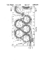
- FIGS. 3A, 3B and 3C when overlapped as indicated, show a plan view, partially broken away to the horizontal center plane of the apparatus, of a four cell apparatus according to the invention.
- FIG. 4 shows a schematic sectional plan view of an embodiment of the invention in which the serpentine wall forms a closed loop with the transport web running along the outside surface.
- FIGS. 1, 2A, 2B and 2C a simplified, single cell embodiment of the invention is illustrated on an expanded scale in which many clearances between and thicknesses of elements have been exaggerated to facilitate illustrating and understanding of the invention.
- the basic geometry shown, however, may be used in the embodiment of FIGS. 3A, 3B and 3C.
- the apparatus according to the invention comprises a housing 2 having a bottom portion 4 and a top portion 6 which may be molded from a plastic material such as Udel Number P-1700 polysulfone or other suitable material compatible with the process liquids used in the apparatus. Since the top portion 6 is essentially a mirror image of the bottom portion 4, but without any process liquid inlets or drains, the following discussion will refer mainly to the bottom portion 4, it being clear that those skilled in the art will understand the geometry of the top portion as well.
- an interior plenum 8 is defined which is bounded by a lower wall 10, an upper wall 12 and a peripheral wall 14 as seen most clearly in FIGS. 2A, 2B and 2C.
- the upper and lower walls include oppositely facing serpentine grooves 16 which snugly receive a stationary serpentine or sinuous wall 18 made from a suitable porous, liquid pervious material such as Porex, a proprietary polyethylene foam available from Porex Technologies of Fairburn, Ga. 30213. In the preferred embodiment of the invention, a 20 to 40 micron porosity is preferred.
- the extreme ends 20 of serpentine wall 18 are snugly received in vertically extending grooves 22 provided in bottom and top portions 4 and 6.
- interior plenum 8 is divided into an inlet plenum 24 having a plurality of process liquid inlets 26 through lower wall 10 and an outlet plenum 28 having a plurality of process liquid drains 30 through wall 10.
- Serpentine wall 18 is formed so as to define a plurality of oppositely opening loops 32, 34 which open alternately into inlet plenum 24 and outlet plenum 28, respectively.
- Such loops need not be identical in size or positioned with symmetry or particular balance on each side of the device, so long as the preferred oppositely opening loops are provided.
- a pump 36 is provided to withdraw a process liquid 38 from a suitable sump 40 and pump such process liquid through inlets 26 into inlet plenum 24.
- drains 30 are connected to drain outlet plenum into sump 40.
- a further pump 41 may be included in the drain lines to sump 40, to reduce the pressure in outlet plenum 28 to subatmospheric.
- a plurality of hollow, at least partially cylindrical bodies 42 are provided which are made of the same porous, liquid pervious material used for serpentine wall 18. These hollow bodies 42 are captured snugly in oppositely facing grooves 44 provided in upper and lower walls 10 and 12, the grooves 44 being positioned to centrally locate bodies 42 within the loops 34 which open into outlet plenum 28. Additional process liquid inlets 46 are provided through lower wall 10 into the interior of bodies 42 and are connected to receive process liquid from pump 36 and deliver that liquid to the interior of bodies 42. Although considerably more moving parts would be required, it is also within the scope of the invention to use freely rotating, liquid pervious rollers in place of bodies 42.
- each body 48 Formed integrally with lower and upper walls 12 are pairs of oppositely extending, at least partially cylindrical bosses or bodies 48 which protrude into the interior of bodies 42 from each end.
- the diameter of each body 48 is chosen to define a circumferential passageway 50 between the body 48 and each hollow body 42.
- the bodies 48 comprise oppositely facing end surfaces 52, 54 which are spaced axially from each other to define a radially extending channel 56 which receives process liquid from inlet 46 and conveys it to circumferential passageway 50.
- the flow through inlet 46 is adjusted during operation so that passageway 50 remains completely full of process liquid.
- lower and upper walls 10, 12 include integrally formed pairs of oppositely extending at least partially cylindrical bosses or bodies 58 which protrude into the loops 32 which open into inlet plenum 24.
- the diameter of each cylindrical boss 58 is chosen to define a circumferential passageway 60 between the boss 58 and the adjacent loop 32.
- the bosses 58 also comprise oppositely facing end surfaces 62, 64 which are spaced axially from each other to define a radially extending channel 66 which receives process liquid from inlet 26 and conveys it to circumferential passageway 60.
- the flow through inlets 26 is adjusted during operation so that inlet plenum 24 remains completely full of process liquid.
- a segmented gasket 68 is captured between bottom portion 4 and top portion 6 to minimize leakage of process liquid from inlet and outlet plenums 24 and 28. Any suitable means such as screws may be used to attach top portion 6 and bottom portion 4.
- a transport web 70 made from a suitable material such as Mylar, is threaded on edge through outlet plenum 28.
- Web 70 enters the housing 2 by means of a web inlet passage 72 which opens into a scavenging plenum 74 having a process liquid drain 76 in its lower wall, drain 76 being connected to sump 40 as shown schematically in FIG. 1.
- plenum 74 From plenum 74, web 70 is led through a further passageway 78 into outlet plenum 28, past a curved guide block 80 and around the exterior surface of cylindrical body 42 through a partially annular passageway 81 defined between cylindrical body 42 and loop 34.
- Rollers 92 serve to squeeze from transport web 70 any excess process liquid which has carried over from outlet plenum 28 so that the excess liquid drains back via drain 90 to sump 40. From scavenging plenum 88, the transport web 70 is led through an outlet passage 94, around a drive roller 96 operatively connected to a suitable motor 98, and then on around idler roller 100 and back into inlet passage 72. If desired, a dryer may be included for transport web 70 at some location outside housing 2, in the familiar manner.
- a process web or film 102 of indefinite length to be treated by the apparatus may be inserted through a film inlet passage 104 and into a nip defined at cylindrical body 42 between transport web 70 and a preferably undriven pinch roller 106 mounted for rotation between bottom and top portions 4 and 6.
- web 102 Once web 102 has become engaged with transport web 70 at the inlet nip, it is carried by web 70 through passageway 81, around loop 32, then back into the next passageway 81 around the next cylindrical body 42.
- the size and number of loops 32, 34 and cylindrical bodies 42 may be increased or decreased for a given speed of web 70.
- web 70 and passageway 81 extend around only a portion of each cylindrical body 42, it is within the scope of the invention to provide a porous wall in each body 42 only over that portion of its circumference facing into passageway 81, with a solid wall over the remaining portion of the circumference.
- web 102 is an exposed photographic medium having an emulsion on one side to be treated by liquid 38, then the emulsion side is positioned to face the serpentine wall 18 where it will be bathed and supported out of contact with wall 18 by a highly agitated flow of process liquid coming through porous wall 18.
- web 102 passes a further pinch roller 108 and then passes to the opposite side of guide block 80 from that taken by transport web 70 in the manner previously described. From that point, web 102 is led out of housing 2 through a passage 110 into an outlet scavenging plenum 112 having a process liquid drain 114 connected to sump 40. Within outlet scavenging plenum 112 are a pair of soft squeegee rollers 116 which engage web 102 to remove excess process liquid in a manner similar to the function achieved by squeegee rollers 92. Then, web 102 passes through a dryer 118 before proceeding to a further processing station.
- tests have been completed on prototype components of a processing apparatus of the type shown in FIGS. 1, 2A, 2B and 2C, which would be particularly suited for processing black and white photographic film, in which the thickness of serpentine wall 18 was 0.250 inch; the outside diameter of loop 32 was 3.320 inch; the inside diameter of loop 34 was 2.880 inch; the outside diameter of cylindrical body 42 was 2.750 inch for a transport web 70 having a thickness of 0.012 inch and a web 102 having a thickness of 0.010 inch; the axial height of channel 56 was 1.000 inch; the radial width of circumferential passageway 50 was 0.020 inch; the radial width of annular passageway 81 was 0.105 inch; the axial height of channel 66 was 1.000 inch; and the radial width of circumferential passageway 60 was 0.020 inch.
- an inlet pressure of 3.5 psi was sufficient to create the desired flow through serpentine wall 18 and cylindrical bodies 42 to both support and treat a web 102 moving through the apparatus on a transport web 70 moving at a speed of 20 inches per minute.
- the temperature of the process liquid would be in the range of 65° to 120° F.
- the inlet plenum 24 is filled by starting pump 36 and venting the interior of housing 2 through suitable vent valves, not illustrated.
- suitable flow of process liquid has been established
- movement of transport web 70 is established by motor 98.
- web 102 may be inserted into the nip between pinch roller 106 and cylindrical body 42.
- the speed of transport web 70 and the rate of flow through the porous walls are adjusted as necessary to provide the desired support for the process film and the necessary residence time within the device to complete the desired treatment. Additional webs 102 may be fed through the apparatus in close succession.
- FIGS. 3A, 3B and 3C taken together, illustrate an embodiment of the invention in which four separate cells of the type shown in FIG. 2A are provided in a single housing with a transport web 70 being used to move web 102 from cell to cell. Between the cells, pairs of squeegee rollers are provided in scavenging plenums to remove process liquid from webs 70 and 102 before they enter the succeeding cell.
- FIGS. 4 and 5 illustrate schematically alternative embodiments of the present invention in which serpentine wall 18 has been formed into a closed or substantially closed loop, rather than the open form illustrated in the preceding Figures.
- serpentine wall 18 has been shaped into a closed form having four inwardly facing loops and four outwardly facing loops.
- Transport web 70 and web 102 are led over the exterior surface of serpentine wall 18 and, at the outwardly facing loops, between serpentine wall 18 and adjacent cylindrical bodies 42.
- any number of inwardly and outwardly facing loops could be used in such a closed form arrangement.
- FIG. 5 shows an embodiment of the invention in which serpentine wall 18 has been shaped into a closed form having three inwardly facing loops and three outwardly facing loops with access passages being provided for transport web 70 and web 102 to move along the inner surface of serpentine wall 18 and, at the inwardly facing loops, between serpentine wall 18 and cylindrical bodies 42.
- the drive arrangements for transport web 70 and the feed and take-up reels for web 102 have been illustrated on the exterior of the apparatus, those skilled in the art will appreciate that they can be located within the confines of serpentine wall 18 if desired.
Landscapes
- Physics & Mathematics (AREA)
- General Physics & Mathematics (AREA)
- Photographic Processing Devices Using Wet Methods (AREA)
Priority Applications (5)
| Application Number | Priority Date | Filing Date | Title |
|---|---|---|---|
| US07/388,458 US4965618A (en) | 1989-08-02 | 1989-08-02 | Method and apparatus for transporting and liquid treating indeterminate lengths of web material |
| JP2511128A JP2818621B2 (ja) | 1989-08-02 | 1990-07-30 | ウェブ材料を搬送しかつ液体処理する方法および装置 |
| PCT/US1990/004242 WO1991002291A1 (en) | 1989-08-02 | 1990-07-30 | Method and apparatus for transporting and liquid treating indeterminate lengths of web material |
| DE69004792T DE69004792T2 (de) | 1989-08-02 | 1990-07-30 | Verfahren und gerät zum transport und zur flüssigkeitsbehandlung von unbestimmten längen bandmaterial. |
| EP90911491A EP0436699B1 (de) | 1989-08-02 | 1990-07-30 | Verfahren und gerät zum transport und zur flüssigkeitsbehandlung von unbestimmten längen bandmaterial |
Applications Claiming Priority (1)
| Application Number | Priority Date | Filing Date | Title |
|---|---|---|---|
| US07/388,458 US4965618A (en) | 1989-08-02 | 1989-08-02 | Method and apparatus for transporting and liquid treating indeterminate lengths of web material |
Publications (1)
| Publication Number | Publication Date |
|---|---|
| US4965618A true US4965618A (en) | 1990-10-23 |
Family
ID=23534193
Family Applications (1)
| Application Number | Title | Priority Date | Filing Date |
|---|---|---|---|
| US07/388,458 Expired - Fee Related US4965618A (en) | 1989-08-02 | 1989-08-02 | Method and apparatus for transporting and liquid treating indeterminate lengths of web material |
Country Status (5)
| Country | Link |
|---|---|
| US (1) | US4965618A (de) |
| EP (1) | EP0436699B1 (de) |
| JP (1) | JP2818621B2 (de) |
| DE (1) | DE69004792T2 (de) |
| WO (1) | WO1991002291A1 (de) |
Cited By (2)
| Publication number | Priority date | Publication date | Assignee | Title |
|---|---|---|---|---|
| US5313242A (en) * | 1993-04-27 | 1994-05-17 | Eastman Kodak Company | Thru-wall web processing apparatus |
| US20060029908A1 (en) * | 2004-08-09 | 2006-02-09 | Allred Peter M | Treatment devices for providing oral treatments and kits and methods that utilize such treatment devices |
Citations (11)
| Publication number | Priority date | Publication date | Assignee | Title |
|---|---|---|---|---|
| US2861508A (en) * | 1956-12-10 | 1958-11-25 | Unicorn Engineering Corp | Processing machine for sensitized paper and the like |
| US3170382A (en) * | 1960-01-16 | 1965-02-23 | Agfa Ag | Photographic developing machine |
| US3277810A (en) * | 1964-04-22 | 1966-10-11 | Seymour L Hersh | Linear photographic processing system |
| US3366025A (en) * | 1965-01-04 | 1968-01-30 | Naca Equipment Corp | Roller type automatic processor |
| US3507650A (en) * | 1966-01-11 | 1970-04-21 | Polaroid Corp | Method of depositing viscous photographic reagents |
| US3616742A (en) * | 1969-03-25 | 1971-11-02 | Duwayne E Gilkey | Porous roller film transport and processing system |
| US3831612A (en) * | 1972-09-15 | 1974-08-27 | Eastman Kodak Co | Apparatus for treating a material |
| US3968510A (en) * | 1973-07-02 | 1976-07-06 | Eastman Kodak Company | Conduit for processing webs with a liquid solution |
| US4003070A (en) * | 1974-04-04 | 1977-01-11 | Merz & Co. | Apparatus for treating photographic materials |
| US4025937A (en) * | 1975-08-15 | 1977-05-24 | Eastman Kodak Company | Web transport apparatus |
| US4187022A (en) * | 1978-02-03 | 1980-02-05 | Labortechnik M. R. Walter | Apparatus for transporting webs of photosensitive material |
Family Cites Families (2)
| Publication number | Priority date | Publication date | Assignee | Title |
|---|---|---|---|---|
| FR106318A (de) * | 1970-11-19 | |||
| GB1527353A (en) * | 1974-10-15 | 1978-10-04 | Agfa Gevaert | Apparatus for use in processing sheets or strips of recording material |
-
1989
- 1989-08-02 US US07/388,458 patent/US4965618A/en not_active Expired - Fee Related
-
1990
- 1990-07-30 EP EP90911491A patent/EP0436699B1/de not_active Expired - Lifetime
- 1990-07-30 DE DE69004792T patent/DE69004792T2/de not_active Expired - Fee Related
- 1990-07-30 WO PCT/US1990/004242 patent/WO1991002291A1/en not_active Ceased
- 1990-07-30 JP JP2511128A patent/JP2818621B2/ja not_active Expired - Lifetime
Patent Citations (11)
| Publication number | Priority date | Publication date | Assignee | Title |
|---|---|---|---|---|
| US2861508A (en) * | 1956-12-10 | 1958-11-25 | Unicorn Engineering Corp | Processing machine for sensitized paper and the like |
| US3170382A (en) * | 1960-01-16 | 1965-02-23 | Agfa Ag | Photographic developing machine |
| US3277810A (en) * | 1964-04-22 | 1966-10-11 | Seymour L Hersh | Linear photographic processing system |
| US3366025A (en) * | 1965-01-04 | 1968-01-30 | Naca Equipment Corp | Roller type automatic processor |
| US3507650A (en) * | 1966-01-11 | 1970-04-21 | Polaroid Corp | Method of depositing viscous photographic reagents |
| US3616742A (en) * | 1969-03-25 | 1971-11-02 | Duwayne E Gilkey | Porous roller film transport and processing system |
| US3831612A (en) * | 1972-09-15 | 1974-08-27 | Eastman Kodak Co | Apparatus for treating a material |
| US3968510A (en) * | 1973-07-02 | 1976-07-06 | Eastman Kodak Company | Conduit for processing webs with a liquid solution |
| US4003070A (en) * | 1974-04-04 | 1977-01-11 | Merz & Co. | Apparatus for treating photographic materials |
| US4025937A (en) * | 1975-08-15 | 1977-05-24 | Eastman Kodak Company | Web transport apparatus |
| US4187022A (en) * | 1978-02-03 | 1980-02-05 | Labortechnik M. R. Walter | Apparatus for transporting webs of photosensitive material |
Cited By (3)
| Publication number | Priority date | Publication date | Assignee | Title |
|---|---|---|---|---|
| US5313242A (en) * | 1993-04-27 | 1994-05-17 | Eastman Kodak Company | Thru-wall web processing apparatus |
| US20060029908A1 (en) * | 2004-08-09 | 2006-02-09 | Allred Peter M | Treatment devices for providing oral treatments and kits and methods that utilize such treatment devices |
| US7625210B2 (en) * | 2004-08-09 | 2009-12-01 | Ultradent Products, Inc. | Treatment devices for providing oral treatments and kits and methods that utilize such treatment devices |
Also Published As
| Publication number | Publication date |
|---|---|
| WO1991002291A1 (en) | 1991-02-21 |
| DE69004792T2 (de) | 1994-06-09 |
| EP0436699B1 (de) | 1993-11-24 |
| DE69004792D1 (de) | 1994-01-05 |
| JPH04500873A (ja) | 1992-02-13 |
| EP0436699A1 (de) | 1991-07-17 |
| JP2818621B2 (ja) | 1998-10-30 |
Similar Documents
| Publication | Publication Date | Title |
|---|---|---|
| US3372630A (en) | Apparatus for processing light sensitive film | |
| US3186326A (en) | Fluid bearings for strip material | |
| US5144474A (en) | Perforated processing apparatus and method | |
| US2401185A (en) | Continuous film processing apparatus | |
| US4965618A (en) | Method and apparatus for transporting and liquid treating indeterminate lengths of web material | |
| US5381203A (en) | Textured surface with canted channels for an automatic tray processor | |
| US4003070A (en) | Apparatus for treating photographic materials | |
| JP2928093B2 (ja) | モジュラー処理チャネルを有する感光材処理装置 | |
| US2570627A (en) | Film processing device | |
| US3336853A (en) | Apparatus for treating sheet-form materials | |
| US5772765A (en) | Device for processing flat workpieces, in particular printed circuit boards | |
| US3165047A (en) | Photographic processing apparatus | |
| US3538837A (en) | Photocopy development method and device | |
| EP0517712B1 (de) | Verbesserungen bezüglich eines photographischen entwicklungsgerätes | |
| US5239327A (en) | Processor for light sensitive material | |
| US3735689A (en) | Roller tray photographic processing apparatus | |
| US5353086A (en) | Textured surface with canted channels for an automatic tray processor | |
| US4025937A (en) | Web transport apparatus | |
| US3041953A (en) | Film developing apparatus | |
| US5093678A (en) | Processor with laminar fluid flow wick | |
| US4937607A (en) | Apparatus and method for processing photosensitive sheets | |
| JPH08314103A (ja) | 写真シート材料の湿式処理装置 | |
| JP2799313B2 (ja) | 写真用シート材料の湿式処理装置 | |
| US3780637A (en) | Photographic material processing apparatus | |
| US5250975A (en) | Apparatus for simultaneously processing plural webs of photosensitive material |
Legal Events
| Date | Code | Title | Description |
|---|---|---|---|
| AS | Assignment |
Owner name: EASTMAN KODAK COMPANY, ROCHESTER NEW YORK A CORP O Free format text: ASSIGNMENT OF ASSIGNORS INTEREST.;ASSIGNORS:DEVANEY, MARK J. JR.;WANNENWETSCH, EDWARD H.;REEL/FRAME:005111/0033;SIGNING DATES FROM 19890724 TO 19890727 |
|
| FEPP | Fee payment procedure |
Free format text: PAYOR NUMBER ASSIGNED (ORIGINAL EVENT CODE: ASPN); ENTITY STATUS OF PATENT OWNER: LARGE ENTITY |
|
| FPAY | Fee payment |
Year of fee payment: 4 |
|
| FEPP | Fee payment procedure |
Free format text: PAYER NUMBER DE-ASSIGNED (ORIGINAL EVENT CODE: RMPN); ENTITY STATUS OF PATENT OWNER: LARGE ENTITY Free format text: PAYOR NUMBER ASSIGNED (ORIGINAL EVENT CODE: ASPN); ENTITY STATUS OF PATENT OWNER: LARGE ENTITY |
|
| FPAY | Fee payment |
Year of fee payment: 8 |
|
| REMI | Maintenance fee reminder mailed | ||
| LAPS | Lapse for failure to pay maintenance fees | ||
| STCH | Information on status: patent discontinuation |
Free format text: PATENT EXPIRED DUE TO NONPAYMENT OF MAINTENANCE FEES UNDER 37 CFR 1.362 |
|
| FP | Lapsed due to failure to pay maintenance fee |
Effective date: 20021023 |