US4962952A - Pressure tube with deflecting section - Google Patents
Pressure tube with deflecting section Download PDFInfo
- Publication number
- US4962952A US4962952A US07/329,980 US32998089A US4962952A US 4962952 A US4962952 A US 4962952A US 32998089 A US32998089 A US 32998089A US 4962952 A US4962952 A US 4962952A
- Authority
- US
- United States
- Prior art keywords
- tube
- grooves
- wall
- bore
- axial
- Prior art date
- Legal status (The legal status is an assumption and is not a legal conclusion. Google has not performed a legal analysis and makes no representation as to the accuracy of the status listed.)
- Expired - Fee Related
Links
- 239000002184 metal Substances 0.000 claims description 16
- 238000007789 sealing Methods 0.000 claims description 5
- 230000036316 preload Effects 0.000 claims description 3
- 241000282472 Canis lupus familiaris Species 0.000 description 2
- 238000005452 bending Methods 0.000 description 2
- 230000004323 axial length Effects 0.000 description 1
- 230000006835 compression Effects 0.000 description 1
- 238000007906 compression Methods 0.000 description 1
- 238000005553 drilling Methods 0.000 description 1
- 238000004519 manufacturing process Methods 0.000 description 1
- 239000007787 solid Substances 0.000 description 1
Images

Classifications
-
- E—FIXED CONSTRUCTIONS
- E21—EARTH DRILLING; MINING
- E21B—EARTH DRILLING, e.g. DEEP DRILLING; OBTAINING OIL, GAS, WATER, SOLUBLE OR MELTABLE MATERIALS OR A SLURRY OF MINERALS FROM WELLS
- E21B33/00—Sealing or packing boreholes or wells
- E21B33/02—Surface sealing or packing
- E21B33/03—Well heads; Setting-up thereof
- E21B33/035—Well heads; Setting-up thereof specially adapted for underwater installations
- E21B33/038—Connectors used on well heads, e.g. for connecting blow-out preventer and riser
Definitions
- This invention relates in general to subsea well equipment, and in particular to a pressure tube which connects coaxial bores of two members together.
- One type of subsea well structure utilizes a subsea wellhead housing.
- a casing hanger lands in the wellhead housing and supports a string of casing.
- a wellhead connector is lowered from the surface, landed on top of and connected to the wellhead housing.
- the wellhead connector has a bore that is coaxial with the bore in the casing hanger.
- a tube interconnects the two coaxial bores.
- the bores may not be precisely aligned. This requires the tube to bend slightly. Elastomeric seals will accommodate some radial movement. However, misalignment is more of a problem with metal seals.
- the tube of this invention interconnects two coaxial bores of a subsea wellhead assembly.
- the tube has an inner wall, an outer wall, a first end and a second end.
- One of the ends of the tubes is rigidly connected to the first member.
- the other end of the tube extends into the bore of the second member.
- a deflection section is located between the ends of the tube.
- the deflecting section is made up of inner and outer grooves formed in the wall of the tube. The grooves are circumferential. The inner and outer grooves alternate with each other along the axis of the tubing.
- the axial dimension of the grooves is substantially less than the axial distance between the grooves. This provides substantial axial strength to the tube. Also, the radial distance from the inner wall of the tube to each outer groove, and the radial distance from the outer wall of the tube to each inner groove is much greater than the axial dimension of each groove. Both of these together provide substantial strength to withstand high pressure.
- the second end of the tube is free for slight axial movement within the bore of the second member.
- the second end of the tube bears against a shoulder in the second member.
- the length of the tube is selected to compress the second end against this shoulder for a metal-to-metal seal.
- the radial depths of the grooves are selected in the second embodiment to provide an axial force upon application of internal pressure, or selected to provide axial force from external pressure, or both.
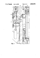
- FIG. 1 is a vertical sectional view illustrating a portion of a wellhead having a tube constructed in accordance with this invention.
- FIG. 2 is a partial sectional view of the tube shown in FIG. 1.
- FIG. 3 is a partial sectional view of an alternate embodiment of a tube.
- wellhead housing 11 will be of a type that is supported on a sea floor.
- Wellhead housing 11 has a bore 12 which contains at least one casing hanger 13.
- the casing hanger 13 is a conventional member that is located at the upper end of a string of casing (not shown).
- a packoff 15 seals between the exterior of the casing hanger 13 and the wellhead housing 11.
- the casing hanger 13 has a cylindrical bore 17.
- a set of exterior grooves 19 are located on the wellhead housing 11.
- a wellhead connector 21 lands on top of the wellhead housing 11.
- the wellhead connector 21 will be connected to the lower end of a string of riser (not shown) which extends to a drilling or production vessel at the surface.
- a seal 23 seals between the wellhead connector 21 and the wellhead housing 11.
- a plurality of dogs 25 carried in the wellhead connector 21 engage the grooves 19.
- a cam 27 moves from an upper position to a lower position, pushing the dogs 25 inward into the engaged position.
- a hydraulic cylinder 29 serves to move the cam 27 between the upper and lower positions.
- the wellhead connector 21 has a bore 31 which is coaxial with the bore 17 of the casing hanger 13.
- a tube 33 extends between the bore 31 and the bore 17 to seal the interior of these bores from the bore 12 of the wellhead housing 11.
- Tube 33 has an upper or first end which rigidly attaches the tube 33 to the wellhead connector 21.
- the means for attachment includes an integral flange 35 located on the upper end of the tube 33. Flange 35 fits within a counterbore 37 located in the wellhead connector 21.
- a metal seal 39 seals the upper end of the tube 33.
- the lower termination of a riser (not shown) will be connected to the upper end of the tube 33 and to the wellhead connector 21.
- Tube 33 has a second end that extends into the casing hanger bore 17.
- Tube 33 has an integrally formed deflection section 40 which allows slight axial and bending deflection. Bending deflection in section 40 allows radial deflection of the lower end of tube 33.
- the deflection section 40 is located entirely within the bore 31 of the wellhead connector 21.
- the axial length of the deflection section 40 may be as much as one-half the total length of the tube 33 from the flange 35 to the lower or second end.
- Deflection section 40 includes a plurality of inner grooves 41 and outer grooves 43. All of the grooves 41, 43 are cut into an enlarged section of the solid wall of the tube 33.
- All of the grooves 41, 43 are located in planes perpendicular to the axis of the tube 33.
- the inner grooves 41 extend outward from the inner wall 42 of the tube 33.
- the outer grooves 43 extend inward from the outer wall 44 of the tube 33.
- the grooves 41, 43 are staggered, with an inner groove 41 located between each outer groove 43.
- the radial extent or dimension of each groove 41, 43 is greater than one-half the radial distance from the inner wall 42 to the outer wall 44.
- the deflecting area is sized so that it is substantially rigid both in radial and axial directions, capable of only slight deflection of about 2 to 5 percent. This is accommodated by making the grooves 41, 43 rather thin compared to the metal cross-section in the deflecting section 40.
- Each groove 41, 43 preferably has the same axial dimension or thickness 45, as shown in FIG. 2.
- Each groove, 41, 43 preferably is positioned the same axial distance 47 from one of the grooves 41 to the next groove 43.
- the axial thickness 45 is much less than the axial distance 47, preferably about one-half.
- each inner groove 41 and the outer wall 44 there is a fairly large outer radial distance 49 between the bottom or base 41a of each inner groove 41 and the outer wall 44.
- the inner radial distance 51 and the outer radial distance 49 are not necessarily equal. However, each is substantially larger than the axial thickness 45 of each groove 41, 43.
- the inner radial distance 51 and the outer radial distance 49 are each about twice the magnitude of the axial thickness 45 of each groove 41, 43.
- the lower or second end of the tube 33 has a plurality of elastomeric seals 53 that sealingly engage the bore 17 of the casing hanger 13.
- a metal seal 55 provides metal-to-metal sealing between the tube 33 and the bore 17.
- a retainer 57 holds the metal seal 55 in place.
- the radial lengths of the inner grooves 41 and the outer grooves 43 can be varied to provide minimum axial loading due to pressure.
- Axial force or loading can result from pressure being applied to the interior or exterior of the tube 33.
- the pressure in the tube 33 will tend to force the axial thickness of the inner grooves 41 to increase.
- the tube 33 will tend to elongate.
- This internal pressure also acts on the metal seal 55, tending to compress the tube 33. If the base 41a of each inner groove 41 has the same diameter as the bore 17 at seal 55, as shown in FIG. 2, then the compression and tension forces will offset each other. There will be no axial stress in the tube 33 in that case as a result of internal pressure.
- each outer grooves 43 can be selected to equal the diameter of bore 17 to balance axial forces on the tube 33 due to external pressure. If both internal and external forces are expected, the radial depths of the grooves 41, 43 can be selected to reduce the axial forces on the tube 33 to a minimum.
- casing hanger 13 In operation, casing hanger 13 will be landed in the wellhead housing 11. Packoff 15 is set between the casing hanger 13 and the wellhead housing 11. The tube 33 will be fastened to the wellhead connector 21. The wellhead connector 21 is lowered over the wellhead housing 11. The tube 33 will insert into the bore 17 of the casing hanger 13. Slight radial deflection in the deflecting section 40 allows the tube 33 to move laterally slightly to align with the bore 17 even though the bore 17 may be slightly out of alignment with the axis of the bore 31. This assures that the metal seal 55 (FIG. 2) seals properly.
- the bore 17' of casing hanger 13' has a frusto-conical shoulder 59 directly below a cylindrical portion of the bore 17'.
- Elastomeric seals 53' on the lower end of the tube 33' seal against the cylindrical portion of the bore 17'.
- Shoulder 59 tapers relative to vertical at about 10 degrees.
- the tube 33' has a shoulder 61 below the seals 53' which tapers relative to vertical at about 8 degrees.
- the tube 33' is sized so that it will compress slightly in the deflection section 40' when the shoulder 61 contacts the shoulder 59. This preloads the shoulder 61 against the shoulder 59, providing a metal-to-metal seal. The difference in the angles of 10 degrees and 8 degrees between the shoulders 59 and 61 assures a metal-to-metal contact.
- the diameter of the base of each outer groove 43' has a diameter that is less than the inner diameter of the bore 17' immediately above shoulder 59.
- FIG. 3 preferably has inner grooves 41' sized to provide a positive axial compressive force on tube 33' when under internal pressure.
- the base of each inner groove 41' is greater in diameter than the inner diameter of bore 17' immediately above shoulder 59 by a difference 63. Internal pressure will tend to elongate the tube 33', increasing the compressive force between the shoulder 61 and shoulder 59. This tends to increase the ability of the metal seal formed by the shoulders 59, 61 to withstand internal pressure.
- the invention has significant advantages.
- the deflecting member in the tube allows slight radial deflection to accommodate for slightly misaligned bores.
- This deflecting section is sufficiently strong due to the thin size of the groove to withstand great pressures.
- the deflecting section will also transmit axial load in the event that the tube is preloaded axially against the shoulder in the casing hanger.
- the grooves may be dimensioned in radial directions to balance axial forces due to pressure, or to provide a compressive axial force.
Abstract
Description
Claims (4)
Priority Applications (4)
| Application Number | Priority Date | Filing Date | Title |
|---|---|---|---|
| US07/329,980 US4962952A (en) | 1989-03-29 | 1989-03-29 | Pressure tube with deflecting section |
| GB9005643A GB2229782B (en) | 1989-03-29 | 1990-03-13 | Pressure tube with deflecting section |
| NO901156A NO179494C (en) | 1989-03-29 | 1990-03-13 | Connector for connecting a production ladder pipe to a subsea wellhead |
| SG6394A SG6394G (en) | 1989-03-29 | 1994-01-17 | Pressure tube with deflecting section |
Applications Claiming Priority (1)
| Application Number | Priority Date | Filing Date | Title |
|---|---|---|---|
| US07/329,980 US4962952A (en) | 1989-03-29 | 1989-03-29 | Pressure tube with deflecting section |
Publications (1)
| Publication Number | Publication Date |
|---|---|
| US4962952A true US4962952A (en) | 1990-10-16 |
Family
ID=23287838
Family Applications (1)
| Application Number | Title | Priority Date | Filing Date |
|---|---|---|---|
| US07/329,980 Expired - Fee Related US4962952A (en) | 1989-03-29 | 1989-03-29 | Pressure tube with deflecting section |
Country Status (3)
| Country | Link |
|---|---|
| US (1) | US4962952A (en) |
| GB (1) | GB2229782B (en) |
| NO (1) | NO179494C (en) |
Cited By (3)
| Publication number | Priority date | Publication date | Assignee | Title |
|---|---|---|---|---|
| US5255743A (en) * | 1991-12-19 | 1993-10-26 | Abb Vetco Gray Inc. | Simplified wellhead connector |
| US6321843B2 (en) * | 1998-07-23 | 2001-11-27 | Cooper Cameron Corporation | Preloading type connector |
| US20090230679A1 (en) * | 2005-05-27 | 2009-09-17 | Josef Mocivnik | Pipe Connection |
Citations (11)
| Publication number | Priority date | Publication date | Assignee | Title |
|---|---|---|---|---|
| US3070387A (en) * | 1959-11-02 | 1962-12-25 | John F Peyton | Bellows restraining device |
| US3095220A (en) * | 1959-02-16 | 1963-06-25 | Herrick L Johnston Inc | Zero load pump flange connection |
| US3239250A (en) * | 1962-10-01 | 1966-03-08 | Litton Systems Inc | Coupling for hollow structures |
| US3248130A (en) * | 1965-04-02 | 1966-04-26 | Warner P Knight | System and method for running and hanging tubing in a well |
| US3273646A (en) * | 1966-09-20 | Circulating casing hanger assembly | ||
| US3319979A (en) * | 1964-04-03 | 1967-05-16 | Curt P Herold | Quick attach and release fluid coupling assembly |
| US3561527A (en) * | 1968-11-01 | 1971-02-09 | Vetco Offshore Ind Inc | Hydraulically set casing hanger apparatus and packing sleeve |
| US4350372A (en) * | 1980-01-21 | 1982-09-21 | Logsdon Duane D | Expansion coupling for large diameter plastic pipes |
| US4469467A (en) * | 1982-01-18 | 1984-09-04 | The Cretex Companies, Inc. | Manhole chimney seal |
| US4732396A (en) * | 1985-10-08 | 1988-03-22 | Great Lakes Chemical Corporation | Apparatus and method for sealing a rotating shaft |
| US4819967A (en) * | 1983-02-14 | 1989-04-11 | Vetco Gray Inc. | Conductor tieback connector |
Family Cites Families (1)
| Publication number | Priority date | Publication date | Assignee | Title |
|---|---|---|---|---|
| JPS59501676A (en) * | 1982-10-14 | 1984-10-04 | エフ・エム・シ−・コ−ポレ−ション | Pipe row tieback fittings |
-
1989
- 1989-03-29 US US07/329,980 patent/US4962952A/en not_active Expired - Fee Related
-
1990
- 1990-03-13 NO NO901156A patent/NO179494C/en unknown
- 1990-03-13 GB GB9005643A patent/GB2229782B/en not_active Expired - Lifetime
Patent Citations (11)
| Publication number | Priority date | Publication date | Assignee | Title |
|---|---|---|---|---|
| US3273646A (en) * | 1966-09-20 | Circulating casing hanger assembly | ||
| US3095220A (en) * | 1959-02-16 | 1963-06-25 | Herrick L Johnston Inc | Zero load pump flange connection |
| US3070387A (en) * | 1959-11-02 | 1962-12-25 | John F Peyton | Bellows restraining device |
| US3239250A (en) * | 1962-10-01 | 1966-03-08 | Litton Systems Inc | Coupling for hollow structures |
| US3319979A (en) * | 1964-04-03 | 1967-05-16 | Curt P Herold | Quick attach and release fluid coupling assembly |
| US3248130A (en) * | 1965-04-02 | 1966-04-26 | Warner P Knight | System and method for running and hanging tubing in a well |
| US3561527A (en) * | 1968-11-01 | 1971-02-09 | Vetco Offshore Ind Inc | Hydraulically set casing hanger apparatus and packing sleeve |
| US4350372A (en) * | 1980-01-21 | 1982-09-21 | Logsdon Duane D | Expansion coupling for large diameter plastic pipes |
| US4469467A (en) * | 1982-01-18 | 1984-09-04 | The Cretex Companies, Inc. | Manhole chimney seal |
| US4819967A (en) * | 1983-02-14 | 1989-04-11 | Vetco Gray Inc. | Conductor tieback connector |
| US4732396A (en) * | 1985-10-08 | 1988-03-22 | Great Lakes Chemical Corporation | Apparatus and method for sealing a rotating shaft |
Cited By (3)
| Publication number | Priority date | Publication date | Assignee | Title |
|---|---|---|---|---|
| US5255743A (en) * | 1991-12-19 | 1993-10-26 | Abb Vetco Gray Inc. | Simplified wellhead connector |
| US6321843B2 (en) * | 1998-07-23 | 2001-11-27 | Cooper Cameron Corporation | Preloading type connector |
| US20090230679A1 (en) * | 2005-05-27 | 2009-09-17 | Josef Mocivnik | Pipe Connection |
Also Published As
| Publication number | Publication date |
|---|---|
| NO179494B (en) | 1996-07-08 |
| GB9005643D0 (en) | 1990-05-09 |
| GB2229782B (en) | 1992-11-18 |
| GB2229782A (en) | 1990-10-03 |
| NO179494C (en) | 1996-10-16 |
| NO901156D0 (en) | 1990-03-13 |
| NO901156L (en) | 1990-10-01 |
Similar Documents
| Publication | Publication Date | Title |
|---|---|---|
| AU606428B2 (en) | Subsea casing hanger packoff assembly | |
| US5555935A (en) | Fluid connector for well | |
| US5971076A (en) | Subsea wellhead structure for transferring large external loads | |
| US8567513B2 (en) | Hydraulic surface connector | |
| US4374595A (en) | Metal to metal sealed joint for tubing string | |
| US6896076B2 (en) | Rotating drilling head gripper | |
| US20060191680A1 (en) | Metal-to-metal seal for bridging hanger or tieback connection | |
| US7467663B2 (en) | High pressure wellhead assembly interface | |
| US7240735B2 (en) | Subsea wellhead assembly | |
| US20120098203A1 (en) | Energizing ring nose profile and seal entrance | |
| US4641841A (en) | Metal seal for a tubular connection | |
| US5423575A (en) | Concentric riser joint with self-aligning coupling | |
| US6450507B2 (en) | Water ingress seal for tapered seals | |
| GB2213225A (en) | Subsea multiway hydraulic connector | |
| EP0292084A2 (en) | Production tieback connector | |
| EP1947290B1 (en) | Riser with axially offset dog-type connectors | |
| US9145752B2 (en) | Clamping arrangement | |
| US5247996A (en) | Self preloading connection for a subsea well assembly | |
| US4962952A (en) | Pressure tube with deflecting section | |
| US4589689A (en) | Energized seal for upper termination | |
| CA1181001A (en) | Production casing tieback connector assembly | |
| CA1309120C (en) | Tubular connector | |
| CA2191280A1 (en) | Adjustable casing hanger with contractible load shoulder and metal sealing ratch latch adjustment sub | |
| US4797029A (en) | Remotely installing a tubular string | |
| US6615915B2 (en) | High pressure side-by-side wellhead system |
Legal Events
| Date | Code | Title | Description |
|---|---|---|---|
| AS | Assignment |
Owner name: VETCO GRAY INC., A CORP. OF DE., TEXAS Free format text: ASSIGNMENT OF ASSIGNORS INTEREST.;ASSIGNOR:WALD, GLENN M.;REEL/FRAME:005074/0262 Effective date: 19890321 Owner name: VETCO GRAY INC., A CORP. OF DE., TEXAS Free format text: ASSIGNMENT OF ASSIGNORS INTEREST.;ASSIGNOR:PALLINI, JOSEPH W. JR.;REEL/FRAME:005074/0264 Effective date: 19890321 |
|
| AS | Assignment |
Owner name: CITIBANK, N.A., AS AGENT Free format text: SECURITY INTEREST;ASSIGNOR:VETCO GRAY INC.;REEL/FRAME:005211/0237 Effective date: 19891128 |
|
| FEPP | Fee payment procedure |
Free format text: PAYOR NUMBER ASSIGNED (ORIGINAL EVENT CODE: ASPN); ENTITY STATUS OF PATENT OWNER: LARGE ENTITY |
|
| FPAY | Fee payment |
Year of fee payment: 4 |
|
| FEPP | Fee payment procedure |
Free format text: PAYER NUMBER DE-ASSIGNED (ORIGINAL EVENT CODE: RMPN); ENTITY STATUS OF PATENT OWNER: LARGE ENTITY Free format text: PAYOR NUMBER ASSIGNED (ORIGINAL EVENT CODE: ASPN); ENTITY STATUS OF PATENT OWNER: LARGE ENTITY |
|
| FPAY | Fee payment |
Year of fee payment: 8 |
|
| FEPP | Fee payment procedure |
Free format text: PAYOR NUMBER ASSIGNED (ORIGINAL EVENT CODE: ASPN); ENTITY STATUS OF PATENT OWNER: LARGE ENTITY Free format text: PAYER NUMBER DE-ASSIGNED (ORIGINAL EVENT CODE: RMPN); ENTITY STATUS OF PATENT OWNER: LARGE ENTITY |
|
| REMI | Maintenance fee reminder mailed | ||
| LAPS | Lapse for failure to pay maintenance fees | ||
| STCH | Information on status: patent discontinuation |
Free format text: PATENT EXPIRED DUE TO NONPAYMENT OF MAINTENANCE FEES UNDER 37 CFR 1.362 |
|
| FP | Lapsed due to failure to pay maintenance fee |
Effective date: 20021016 |