US4948552A - Ultrasonic wave sensor intended to come into contact with a wall at a high temperature and application of this sensor - Google Patents
Ultrasonic wave sensor intended to come into contact with a wall at a high temperature and application of this sensor Download PDFInfo
- Publication number
- US4948552A US4948552A US07/119,275 US11927587A US4948552A US 4948552 A US4948552 A US 4948552A US 11927587 A US11927587 A US 11927587A US 4948552 A US4948552 A US 4948552A
- Authority
- US
- United States
- Prior art keywords
- wall
- sensor
- duct
- wave guide
- contact
- Prior art date
- Legal status (The legal status is an assumption and is not a legal conclusion. Google has not performed a legal analysis and makes no representation as to the accuracy of the status listed.)
- Expired - Fee Related
Links
Images

Classifications
-
- G—PHYSICS
- G01—MEASURING; TESTING
- G01F—MEASURING VOLUME, VOLUME FLOW, MASS FLOW OR LIQUID LEVEL; METERING BY VOLUME
- G01F1/00—Measuring the volume flow or mass flow of fluid or fluent solid material wherein the fluid passes through a meter in a continuous flow
- G01F1/66—Measuring the volume flow or mass flow of fluid or fluent solid material wherein the fluid passes through a meter in a continuous flow by measuring frequency, phase shift or propagation time of electromagnetic or other waves, e.g. using ultrasonic flowmeters
-
- G—PHYSICS
- G10—MUSICAL INSTRUMENTS; ACOUSTICS
- G10K—SOUND-PRODUCING DEVICES; METHODS OR DEVICES FOR PROTECTING AGAINST, OR FOR DAMPING, NOISE OR OTHER ACOUSTIC WAVES IN GENERAL; ACOUSTICS NOT OTHERWISE PROVIDED FOR
- G10K11/00—Methods or devices for transmitting, conducting or directing sound in general; Methods or devices for protecting against, or for damping, noise or other acoustic waves in general
- G10K11/18—Methods or devices for transmitting, conducting or directing sound
- G10K11/24—Methods or devices for transmitting, conducting or directing sound for conducting sound through solid bodies, e.g. wires
-
- G—PHYSICS
- G01—MEASURING; TESTING
- G01F—MEASURING VOLUME, VOLUME FLOW, MASS FLOW OR LIQUID LEVEL; METERING BY VOLUME
- G01F1/00—Measuring the volume flow or mass flow of fluid or fluent solid material wherein the fluid passes through a meter in a continuous flow
- G01F1/66—Measuring the volume flow or mass flow of fluid or fluent solid material wherein the fluid passes through a meter in a continuous flow by measuring frequency, phase shift or propagation time of electromagnetic or other waves, e.g. using ultrasonic flowmeters
- G01F1/662—Constructional details
-
- G—PHYSICS
- G01—MEASURING; TESTING
- G01N—INVESTIGATING OR ANALYSING MATERIALS BY DETERMINING THEIR CHEMICAL OR PHYSICAL PROPERTIES
- G01N2291/00—Indexing codes associated with group G01N29/00
- G01N2291/02—Indexing codes associated with the analysed material
- G01N2291/028—Material parameters
- G01N2291/02836—Flow rate, liquid level
-
- G—PHYSICS
- G01—MEASURING; TESTING
- G01N—INVESTIGATING OR ANALYSING MATERIALS BY DETERMINING THEIR CHEMICAL OR PHYSICAL PROPERTIES
- G01N2291/00—Indexing codes associated with group G01N29/00
- G01N2291/02—Indexing codes associated with the analysed material
- G01N2291/028—Material parameters
- G01N2291/02872—Pressure
Abstract
The ultrasonic wave sensor (2) according to the invention comes into contact with a wall at a high temperature (1) by means of a wave guide (5) made of a vitro-ceramic material. The sensor includes, inside a body (3) made of metallic material, a piezoelectric ceramic pellet (8) connected to an electrical power supply or measurement leads (9). The wave guide (5), also placed in the body (3), is in contact by one of its ends (5b) with the piezoelectric pellet (8) and by its other end (5a) with the wall (1). The body (3) of the sensor is mounted in an articulated manner on a support (21) fixed to the wall (1). The invention applies in particular to the measurement of flow rate in a primary duct of a pressurized-water nuclear reactor.
Description
This application is a continuation-in-part of application Ser. No. 839,291, filed Mar. 13, 1986, now abandoned.
The invention relates to an ultrasonic wave sensor intended to come into contact with a wall at a high temperature, and applications of this sensor, particularly to flow rate measurements.
In industrial installations in which high temperature fluids circulate in ducts, it is very often necessary to measure the velocity or flow rate of those fluids in order to control or monitor the industrial installation. For example, in the case of nuclear power stations incorporating a pressurized-water reactor, it is necessary to know the flow rate of the primary water to a very high degree of accuracy while the reactor is operating. The flow rate can be measured by determining the velocity of propagation of the pressurized water in a primary duct, by measuring the the propagation time of ultrasonic waves in fluid circulating in the duct. In order to do this, use is made of ultrasonic sensors, which can transmit waves into the circulating water and receive these waves after propagation and possible reflection on a wall of the ducting. Prior art sensors actually have to be placed in an opening machined on the inside of the wall of the duct, to limit losses and amplify the amplitude of the received return echo.
Such a sensor mounting, which is described as intrusive in the duct makes the use of these sensors very difficult in the primary circuit of a pressurizedwater nuclear reactor in which the water is at a pressure of the order of 155 105 Pa and at a temperature in the range 280° C. to 320° C. For safety reasons it is in fact necessary to limit as far as possible the number of tappings in the primary ducts of the reactor.
Also, sensors which incorporate a piezoelectric ceramic pellet and a wave guide coupled to that pellet use in their manufacture materials that are generally incapable of withstanding the very high temperatures of the fluid and of the primary ducting.
In the case of a non-intrusive mounting of the sensor, the latter must, however, be in contact, via its wave guide, with the duct wall which is at a very high temperature. Consequently, the wave guide must be designed so as to withstand the temperature without distorting and without excessive expansion, and in such a way that it has a homogeneous, resonant and easily machinable structure, so that its surface coming into contact with the duct wall has a very high surface finish, i.e., of very low roughness. No wave guides having all these characteristics have been known to date.
The purpose of the invention is therefore to propose an ultrasonic wave sensor intended to come into contact with a wall at a high temperature, incorporating, within a body make of a metallic material connected to a support for positioning the sensor on the wall, a piezoelectric ceramic pellet connected an electrical power supply or measuring leads, and placing in contact with one end of a wave guide the other end of which is in contact with the wall when the sensor is in operating position, a sensor which does not have the disadvantages of the devices according to the prior art.
For this purpose, the waveguide consists of a single part made of a vitro-ceramic material, whose end in contact with the wall is machined to a very high surface finish.
In order that the invention may be more clearly under stood, a description will now be given, by way of example, with reference to the appended drawings, of an ultrasonic wave sensor according to the invention and its application to the measurement of the flow rate of pressurized water in a primary ducting of a pressurized-water nuclear reactor.
FIG. 1 is a cross-sectional view of the sensor in operating position on a primary duct of a pressurizedwater nuclear reactor.
FIG. 2 is a view from along line A--A of FIG. 3, on a reduced scale, of the sensor in operating position.
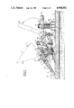
FIG. 3 is a perspective view of a set of two sensors according to the invention which are placed on a duct of the primary circuit of a pressurized-water nuclear reactor, for the measurement of the flow rate of the pressurized water in that duct.
FIG. 4 is a diagrammatic view showing the direction of propagation of the ultrasonic waves in a primary duct of a pressurized-water nuclear reactor.
FIG. 1 shows a primary duct 1 of a pressurized-water nuclear reactor on the outer wall of which has been fixed an ultrasonic sensor represented in solid lines in its operating position and in dot-and-dash lines in its nonoperating position 2', in which the lower surface of the sensor is accessible.
The sensor 2 incorporates a metallic body 3 the front part of which is machined in order to form cooling fins 4. Inside this section of the metal body 3 is arranged the wave guide 5 coming into contact by its surface 5a with the outer surface of the duct 1, filled with water at a temperature of about 300° C. The wave guide 5 is fixed in the body 3 by a screw 6. The end surface 5b of the wave guide 5 away from surface 5a is in contact with a piezoelectric pellet 8 which can be connected by means of electrical leads 9 and a fast-connection terminal 10 to an electrical power supply source and/or to an installation for the retrieval and processing of the signals emitted by the piezoelectric cell 8.
This cell 8 is held in contact with the machined surface 5b of the wave guide 5 at the end of a reduced diameter cylindrical projection of that wave guide by a stop 12 and a centering washer 13 made of material sold under the trade name Permaglass. The centering washer 13 has a thickness greater than the thickness of the cylindrical projection on which the bearing surface 5b of the insert 8 is machined and very slightly less than the sum of the thicknesses of this cylindrical section of the wave guide and of the pellet 8. The stop 12 is pressed against the pellet 8 by a spring 15, held inside the rear part 5b of the metallic body of the sensor, fixed to the front part of this body by means of screws such as 16. The pellet 8 is thus held firmly against the surface 5b of the wave guide 5.
A Peltier effect cell 18 is fitted in part 3b of the metallic body 3, this capsule being supplied with electrical current by means of wires 19 and a fast connection terminal 20. This Peltier effect capsule makes it possible to restrict the temperature inside the metallic body 3 when the sensor is put into operation, as shown in FIG. 1, on a high temperature wall.
The end of the rear part 3b of the metallic body incoporates two holes making it possible to connect the metallic body 3, in an articulated manner, to a support designated generally by reference 21. This support 21 will be described with reference to FIGS. 1 and 2.
The support 21 incorporates two beam sections 22 bearing on the outer surface of the ducting 1, near its upper part, by contact members 23. Beam sections 24 having U-shaped cross sections are fixed at right angles to the beam sections 22 at one of their ends. The beam sections 24 are bored with holes permitting the passage of the ends of a fixing collar 25 the ends of which are threaded to receive a clamping nut 26 fixing the ends of the collar 25 onto the beam sections 24 by means of a spring 27 and a washer 28. On the two parallel beam sections 22 arranged in line with the longitudinal direction of the duct 1 is fixed a support 30 by means of screws 31, which can be seen on FIG. 1. The support 30 incorporates holes permitting the articulated fixing of the body 3 of the sensor. This body 3 is articulated on the support by means of an articulation 33 having a horizontal axis and on the end of an operating lever 35 by means of an articulation 34, also with a horizontal axis. The lever 35 is itself articulated on the support 30 by means of a link 36. The link 36 is articulated on the support 30 by means of an articulation 37 and on the handle 35 by means of an articulation 38, all the articulations having parallel axes. This assembly enables the sensor 2 to be put in its non-opert ing position 2' by raising the handle of the lever 35 from its position represented in solid lines in FIG. 1 to its position 35' represented in a dot-and-dash lines. It is thus easily possible to gain access to the lower surface of the sensor which comes into contact with the duct 1 in operating position.
FIG. 2 shows the positions 25' and 25" of a fixing collar in the case of ducts of decreasing diameters.
The wave guide 5 providing the coupling between the piezoelectric ceramic pellet 8 and the duct 1 must provide perfect coupling, in particular when measurements are to be made in the liquid environment filling the duct. This wave guide must therefore be made of a material having a structure that is homogeneous and resonant, and must be capable of being easily machined so that its surface 5a bearing against the wall in which the measurement is made has a perfect surface finish. This surface finish with very low roughness, obtained by polishing, must be similar to a mirror polish.
In addition, the wave guide must withstand the high temperatures transmitted by the wall of the duct without distortion or excessive expansion.
None of the known materials for the manufacture of wave guides meets these requirements.
The wave guide 5 has been manufactured in a vitroceramic material sold under the trade name Macor by the Corning Glass Company. This material has the following approximate composition:
Silica SiO.sub. 2 : 46%
Alumina Al2 O.sub. 3 : 16%
Magnesia MgO: 17%
Potassium oxide K2 O: 10%
Boron oxide B2 03 7%
Such vitroceramic materials therefore have a composition close to that of glass, and their manufacture and shaping can be carried out using glass manufacturing techniques.
However, after the part has been shaped, it is subjected to heat treatments permitting limited development of crystals within the vitreous mass. This development of crystals is promoted by nucleating agents introduced into the fused material.
Such vitroceramic materials, the composition of which can vary widely, are well known, but have never been used for the production of wave guide making a coupling between a piezoelectric pellet and a high temperature wall.
The wave guide 5 was produced by casting and then crystallization heat treatment of a single part having the indicated composition, then by finishing machining of this part, in particular to produce the bearing surfaces 5a and 5b with a very high surface finish.
This machining of the wave guide, in the case of small diameter ductings, comprises a grinding of the bearing surface 5a of the wave guide in order to make this bearing surface cylindrical. In the case of large diameter ductings, the contact is made along a generatrix of the ducting, the bearing surface 5a being plane.
Wave guide made of vitroceramic material have all the characteristics required for the transmission of ultrasonic waves through a wall at a high temperature, but, at the same time, the material, because of its homogeneity and density, has a relatively high thermal transmission coefficient. This is why, within the metallic body 2, there is provided a Peltier effect capsule 18 which is powered in such a way as to cause an endothermic effect restricting the temperature inside the body of the sensor.
It is that capsule, it is possible to restrict the temperature to about 40° C. in the body of the sensor with a temperature of about 120° C. at the interface 5b between the wave guide 5 and the piezoelectric pellet 8, in the case of a wall 1 at a temperature of about 320° C., which is the maximum temperature of the primary fluid of a pressurized-water nuclear reactor.
It should be noted that the metal body 2 does not come into direct contact with the wall 1, this contact being provided solely by the end of the wave guide 5. The coupling between the wave guide and the ducting 1 can be improved by using a viscous coupling material, for example of the type consisting of an organic agent filled with nickel particles. Such a viscous coupling material is available commercially under the name Never Seez.
With reference to FIGS. 3 and 4, an application of the sensor according to the invention to the measurement of the flow rate in a primary duct of a pressurized-water nuclear reactor will now be described. In fact, in order to measure the flow rate in a primary duct 1 of a pressurized-water nuclear reactor, two identical sensors 2 are used, of the type desribed with reference to FIGS. 1 and 2. These two sensors are arranged facing each other separated by a distance d on the duct 1. The supports 21 of these sensors are assembled by cross-pieces such as 32 and are held by clamping straps 25 on the duct 1. The sensors 2 are pivot-mounted, as described before, on the supports 21 in such a way that they can be placed either in operating position 2 or in non-operating position 2' by raising or lowering the handle 35.
One of the sensors 2 emits an ultrasonic wave which propagates in the pressurized water circulating in the ducting in the direction 40, and which is then reflected by the inner wall of the duct to return along direction 41 towards the second sensor 2. The waves also travel in the opposite direction, sensors 2 being both transmitters and receivers. The distance d is determined so as to produce a sufficient echo despite losses during the travel of the waves inside the duct, in order to make it possible to measure the propagation time of the waves between the two sensors in both directions.
Such a measurement makes it possible to determine the velocity of the pressurized water and therefore its flow rate in the duct 1, this method of measuring a flow rate by ultrasonic waves being well known.
Its principle will now be reviewed with reference to FIG. 4.
The ultrasonic waves are emitted in the direction 42, and pass through the wall of the duct 1 in direction 43 and through the pressurized water circulating in this duct 1 in direction 44 and along the path xy. The direction 44 makes an angle θ with the longitudinal axis of the duct 1 corresponding to the direction of the velocity vector V of the water circulating in the duct. L is the length of the path xy which is greater than the inside diameter of the duct 1. d is the distance along the axial direction of the duct between points x and y.
It can easily be shown, by calculating the propagation time Txy of the waves between x and y and time Tyx of these waves between y and x, that the velocity V of the fluid in the duct can be expressed solely as a function of Txy and Tyx.
This calculation, well known to specialists in the measurement of fluid velocity and flow rate by ultrasonics, shows that: ##EQU1##
The position of the ultrasonic sensors being determined, the expression 2L2 /d is a constant.
V is therefore in the form of a constant which multiplies a propagation time function of the ultrasonic waves between x and y in both directions.
It is therefore very easy to deduce the value of the velocity of the fluid in the duct and its flow rate from the measurement of these propagation times.
This determination of the velocity and that of the flow rate can easily be automated by supplying the propagation times of the waves in both directions in digital form as input data to a computer.
The mounting of sensors shown in FIG. 3 makes it possible to determine the velocity V of the fluid in the duct 1 in the same way but with a double-length path for the waves, which increases the accuracy of the measurement.
In addition, the two sensors 2 are arranged on the same generatrix as the duct 1. This placement of the sensors is easier to implement than a placing on diametrically opposite generatrices.
The angle of incidence of the beam of ultrasonic waves in the pressurized water in the duct is of the order of 17° for an initial incidence of the beam 42 ° of 70°. These values of angle of incidence enable the measurements to be made under very good conditions.
The use of a wave guide made of a vitroceramic material in ultrasonic wave sensors enables very good couplings to be made between the piezoelectric pellet and the wall of the duct, while avoiding distortions or expansions of the wave guide in contact with the duct wall at a high temperature, which would be prejudicial to the obtaining of reproducible measurements.
Furthermore, the fitting of the sensor on its support by articulated means such as have been described enables the sensor to be pivoted and access to its bottom surface to be gained without the need to dismantle the clamping of this support on the duct. The sensor can thus be repositioned extremely accurately on the outer wall of the duct.
The wave guide may have a different shape from that which has been described, and it can be mounted in a different way inside the metal body of the sensor. The end of this wave guide must, however, always project slightly from the metal body in order that it alone comes into contact with the wall at a high temperature.
The method of fixing the piezoelectric pellet and the way in which it contacts one of the ends of the wave guide can be different from that which has been described. it is also possible to envisage a means of cooling the inside of the sensor other than a Peltier capsule.
The sensor can be connected in an articulated manner to the support in a different manner to that which has been described, and can in some cases be fixed rigidly to this support, if it is not necessary to inspect its part which comes into contact with the wall at a high temperature.
The wave guide can be made of a vitroceramic material different from that which has been indicated; this vitroceramic material will be selected in accordance with the application for which the sensor is intended and in particular according to the temperature of the wall on which the wave guide will be applied.
The applications of a sensor the wave guide of which is made of a vitroceramic material such as that which has been described are not limited to the measurement of flow rate in a duct of a primary circuit of a pressurized-water nuclear reactor. Such a sensor could be used for other measurements or non-destructive tests through a wall at a temperature much higher than the primary temperature of a pressurized-water nuclear reactor. In fact, the vitroceramic material such as desribed has characteristics close to those of refractories and can withstand very high temperatures in the order of 1500° C.
Wave guides made of vitroceramic material will always be possible to produce with a very high surface finish, whether this surface finish is produced directly on the cast part or by polishing.
The sensor according to the invention is applicable to any measurement or to any non-destructive test, using ultrasonics, with propagation of ultrasonic waves through a wall at a high temperature.
Claims (9)
1. In an ultrasonic wave sensor coming into contact with a wall at a high temperature (1), incorporating, within a body (3) made of metallic material connected to a support (21) for positioning the sensor (2) on the wall (1), a piezoelectric ceramic pellet (8) connected on an electrical power supply and/or measuring leads (9), a wave guide a first end of which is placed in contact with said piezoelectric ceramic pellet and a second end (5a) of which is in contact with the wall (1) when the sensor (2) is in operating position, wherein the wave guide (5) consists of a single part made of vitroceramic material, i.e., a material of the glass-type entirely free of any crystal structure in the as-cast state, and developing a crystal structure after treatment, said wave guide being manufactured by casting, crystallization heat treatment, and machining incorporating finishing machining of said second end of said wave guide coming into contact with the wall to a mean roughness of 1 to 6 μm, and preferably to a mean roughness of 3.2 μm. .
2. Sensor according to claim 1, wherein the vitroceramic material has approximately the following composition:
Silica SiO2 : 46%
Alumina A12 O3 : 16%
Magnesia MgO : 17%
Potassium oxide K2 O : 10%
Boron oxide B2 O3 : 7%
Fluorine : 4%
3. Sensor according to claim 1 comprising a Peltier effect capsule (18) fitted in the metallic body, (3) in order to restrict the temperature inside said body (3).
4. Ultrasonic wave sensor according to claim 1, wherein the coupling between the end surface (5a) of the wave guide and the wall (1) is made by means of a coupling material, which consists of an organic material containing nickel powder.
5. Ultrasonic wave sensor according to claim 1, wherein the metal body (3) of the sensor is articulated on a support (30) fixed rigidly with respect to the wall (1) and on the end of a lever (35). itself articulated on the support (30) for moving the sensor, by operating the lever, between an operating position in which the wave guide (5) is in contact with the wall (1) and a non-operating position in which the contact end (5a) of the wave guide is accessible.
6. Ultrasonic wave sensor according to claim 5, wherein the lever (35) is articulated on tne support (30) by means of a link (36).
7. Ultrasonic have sensor according to claim 5, in the case in which the wall (1) consists of the outer wall of a duct, wherein the support (30) is fixed on the duct (1) by means of at least one strap (25) clamped round the duct.
8. Application of an ultrasonic sensor according to claim 1 to the measurement of the flow rate of pressurized water in a primary duct of a pressurized-water nuclear reactor.
9. Application according to claim 8, wherein two identical ultrasonic wave sensors separated by a distance(d) are arranged on the same generatrix of the duct (1).
Applications Claiming Priority (2)
| Application Number | Priority Date | Filing Date | Title |
|---|---|---|---|
| FR8503871 | 1985-03-15 | ||
| FR8503871A FR2598498B1 (en) | 1985-03-15 | 1985-03-15 | SENSOR FOR ULTRASONIC WAVES FOR COMING INTO CONTACT WITH A HIGH TEMPERATURE WALL AND APPLICATION THEREOF |
Related Parent Applications (1)
| Application Number | Title | Priority Date | Filing Date |
|---|---|---|---|
| US06839291 Continuation-In-Part | 1986-03-13 |
Publications (1)
| Publication Number | Publication Date |
|---|---|
| US4948552A true US4948552A (en) | 1990-08-14 |
Family
ID=9317248
Family Applications (1)
| Application Number | Title | Priority Date | Filing Date |
|---|---|---|---|
| US07/119,275 Expired - Fee Related US4948552A (en) | 1985-03-15 | 1987-11-06 | Ultrasonic wave sensor intended to come into contact with a wall at a high temperature and application of this sensor |
Country Status (7)
| Country | Link |
|---|---|
| US (1) | US4948552A (en) |
| EP (1) | EP0198731B1 (en) |
| JP (1) | JPS61223518A (en) |
| KR (1) | KR860007538A (en) |
| DE (1) | DE3661334D1 (en) |
| ES (1) | ES8703630A1 (en) |
| FR (1) | FR2598498B1 (en) |
Cited By (19)
| Publication number | Priority date | Publication date | Assignee | Title |
|---|---|---|---|---|
| US5440930A (en) * | 1992-01-31 | 1995-08-15 | Elf Atochem S.A. | Ultrasonic measuring assembly and means for attaching same to a vessel |
| US5824915A (en) * | 1995-08-22 | 1998-10-20 | Krohne A.G. | Volumetric flow meter |
| US6397683B1 (en) | 1998-07-22 | 2002-06-04 | Flowtec Ag | Clamp-on ultrasonic flowmeter |
| US6480793B1 (en) | 2000-10-27 | 2002-11-12 | Westinghouse Electric Company Lcl | Flow condition monitor |
| DE102005052550B3 (en) * | 2005-11-02 | 2007-02-08 | Krohne Ag | Clamp-on ultrasound flow-through measuring device comprises a guiding frame fixed to a fixing unit so that it moves away from or toward a tube and pivots along a pivoting axis |
| DE102006000693A1 (en) * | 2006-01-02 | 2007-07-05 | Endress + Hauser Flowtec Ag | Device for determining and / or monitoring the volume or mass flow of a medium |
| US20070232919A1 (en) * | 2006-03-30 | 2007-10-04 | Krohne Ag | Ultrasonic flow rate measuring device |
| US20070227261A1 (en) * | 2006-03-30 | 2007-10-04 | Krohne Ag | Ultrasonic flow rate measuring device |
| DE102006015218A1 (en) * | 2006-03-30 | 2007-10-11 | Krohne Ag | Clamp-on ultrasonic flow measuring device for use in pipeline system, has transducer for operation with preset ultrasonic frequency, such that thickness of intermediate plate corresponds to quarter of length in adhesive layer |
| DE102006015217A1 (en) * | 2006-03-30 | 2007-10-11 | Krohne Ag | Clamp-on ultrasonic flow measuring device for integration in pipeline system, has fixing device for moving measuring transducer towards and/or away from conduit and for fixation at and/or detachment from guide frame |
| DE102007019689A1 (en) * | 2007-04-24 | 2008-10-30 | Endress + Hauser Flowtec Ag | Device for determining and / or monitoring the volume and / or mass flow of a medium |
| DE102008055167A1 (en) * | 2008-12-29 | 2010-07-01 | Endress + Hauser Flowtec Ag | Measuring system for determining and / or monitoring the flow of a measuring medium through the measuring tube by means of ultrasound |
| EP2324933A2 (en) | 2009-11-19 | 2011-05-25 | Endress+Hauser Flowtec AG | Coupling element of a sensor of an ultrasound flow measuring device |
| WO2012021832A1 (en) * | 2010-08-12 | 2012-02-16 | Aliph, Inc. | Calibration system with clamping system |
| US20120291554A1 (en) * | 2011-05-19 | 2012-11-22 | Hitachi-Ge Nuclear Energy, Ltd. | Heat-Resistant Ultrasonic Sensor and Installation Method Thereof |
| US9288598B2 (en) | 2010-03-22 | 2016-03-15 | Aliph, Inc. | Pipe calibration method for omnidirectional microphones |
| US20200309574A1 (en) * | 2017-09-29 | 2020-10-01 | Micro-Epsilon Messtechnik Gmbh & Co. Kg | Displacement sensor operating without contact |
| US10876871B2 (en) * | 2018-07-12 | 2020-12-29 | Abilene Christian University | Apparatus, systems, and methods for non-invasive measurement of flow in a high temperature pipe |
| RU2799042C2 (en) * | 2018-07-12 | 2023-07-03 | Абилин Кристиан Юниверсити | Device for non-contact flow rate measurement in high-temperature pipe |
Families Citing this family (10)
| Publication number | Priority date | Publication date | Assignee | Title |
|---|---|---|---|---|
| FR2634557A1 (en) * | 1988-07-22 | 1990-01-26 | Pluss Stauffer Ag | DEVICE AND METHOD FOR SIMULTANEOUSLY MEASURING IN A CONDUIT, DENSITY, CONCENTRATION, FLOW SPEED, FLOW AND TEMPERATURE OF A LIQUID OR PASTY FLUID BY ULTRASONIC TRANSMISSION |
| FR2637075B1 (en) * | 1988-09-23 | 1995-03-10 | Gaz De France | METHOD AND DEVICE FOR INDICATING THE FLOW OF A COMPRESSIBLE FLUID FLOWING IN A REGULATOR, AND VIBRATION SENSOR USED FOR THIS PURPOSE |
| DE19861186B4 (en) * | 1998-03-02 | 2005-09-08 | Schubert & Salzer Control Systems Gmbh | System for through flow measurement |
| DE19808701C2 (en) * | 1998-03-02 | 2000-01-20 | Georg F Wagner | Flow measuring device |
| EP0974815B1 (en) * | 1998-07-22 | 2015-09-16 | Endress + Hauser Flowtec AG | Clamp-on ultrasonic sensor arrangement |
| DE102007019610A1 (en) * | 2007-04-24 | 2008-10-30 | Endress + Hauser Flowtec Ag | Device for attaching a measuring or display unit to an object |
| CH700433B1 (en) * | 2007-07-19 | 2010-08-31 | Aquametro Ag | Flow measuring device. |
| DE102007039016A1 (en) * | 2007-08-17 | 2009-02-19 | Endress + Hauser Flowtec Ag | Coupling element for an ultrasonic flowmeter |
| DE102007042663A1 (en) * | 2007-09-10 | 2009-03-12 | Krohne Ag | ultrasound probe |
| CN111380584B (en) * | 2020-04-16 | 2022-02-15 | 上海迅音科技有限公司 | Ultrasonic flowmeter |
Citations (12)
| Publication number | Priority date | Publication date | Assignee | Title |
|---|---|---|---|---|
| US2515221A (en) * | 1948-01-22 | 1950-07-18 | Eugene S Henning | Cathode-ray phase measuring device |
| US3575050A (en) * | 1968-12-04 | 1971-04-13 | Panametrics | Fluid flowmeter |
| US3934457A (en) * | 1975-01-13 | 1976-01-27 | General Electric Company | Vessel nozzle inspection apparatus |
| US4195517A (en) * | 1978-12-18 | 1980-04-01 | The Foxboro Company | Ultrasonic flowmeter |
| GB2060884A (en) * | 1979-10-19 | 1981-05-07 | Panametrics | Ultrasonics transducer |
| GB2086183A (en) * | 1980-10-14 | 1982-05-06 | Leeds & Northrup Co | Doppler flowmeter transducer housing |
| US4392380A (en) * | 1981-02-11 | 1983-07-12 | The United States Of America As Represented By The United States Department Of Energy | High temperature pressure coupled ultrasonic waveguide |
| US4422340A (en) * | 1980-08-19 | 1983-12-27 | Hochtemperatur-Reaktorbau Gmbh | Differential pressure flowmeter for a gas cooled high temperature reactor blower |
| US4454767A (en) * | 1980-03-25 | 1984-06-19 | Fuji Electric Co., Ltd. | Ultrasonic metering device |
| US4783997A (en) * | 1987-02-26 | 1988-11-15 | Panametrics, Inc. | Ultrasonic transducers for high temperature applications |
| JPS64984A (en) * | 1987-06-24 | 1989-01-05 | Canon Inc | Image forming device |
| JPH052296A (en) * | 1990-12-28 | 1993-01-08 | Takao Kawamura | Image forming device |
Family Cites Families (1)
| Publication number | Priority date | Publication date | Assignee | Title |
|---|---|---|---|---|
| DE6944431U (en) * | 1969-11-13 | 1970-04-16 | J U H Krautkraemer Ges Fuer El | ULTRASONIC TEST HEAD |
-
1985
- 1985-03-15 FR FR8503871A patent/FR2598498B1/en not_active Expired - Lifetime
-
1986
- 1986-03-05 DE DE8686400456T patent/DE3661334D1/en not_active Expired
- 1986-03-05 EP EP86400456A patent/EP0198731B1/en not_active Expired
- 1986-03-14 JP JP61056739A patent/JPS61223518A/en active Pending
- 1986-03-14 KR KR1019860001846A patent/KR860007538A/en not_active Application Discontinuation
- 1986-03-14 ES ES553014A patent/ES8703630A1/en not_active Expired
-
1987
- 1987-11-06 US US07/119,275 patent/US4948552A/en not_active Expired - Fee Related
Patent Citations (12)
| Publication number | Priority date | Publication date | Assignee | Title |
|---|---|---|---|---|
| US2515221A (en) * | 1948-01-22 | 1950-07-18 | Eugene S Henning | Cathode-ray phase measuring device |
| US3575050A (en) * | 1968-12-04 | 1971-04-13 | Panametrics | Fluid flowmeter |
| US3934457A (en) * | 1975-01-13 | 1976-01-27 | General Electric Company | Vessel nozzle inspection apparatus |
| US4195517A (en) * | 1978-12-18 | 1980-04-01 | The Foxboro Company | Ultrasonic flowmeter |
| GB2060884A (en) * | 1979-10-19 | 1981-05-07 | Panametrics | Ultrasonics transducer |
| US4454767A (en) * | 1980-03-25 | 1984-06-19 | Fuji Electric Co., Ltd. | Ultrasonic metering device |
| US4422340A (en) * | 1980-08-19 | 1983-12-27 | Hochtemperatur-Reaktorbau Gmbh | Differential pressure flowmeter for a gas cooled high temperature reactor blower |
| GB2086183A (en) * | 1980-10-14 | 1982-05-06 | Leeds & Northrup Co | Doppler flowmeter transducer housing |
| US4392380A (en) * | 1981-02-11 | 1983-07-12 | The United States Of America As Represented By The United States Department Of Energy | High temperature pressure coupled ultrasonic waveguide |
| US4783997A (en) * | 1987-02-26 | 1988-11-15 | Panametrics, Inc. | Ultrasonic transducers for high temperature applications |
| JPS64984A (en) * | 1987-06-24 | 1989-01-05 | Canon Inc | Image forming device |
| JPH052296A (en) * | 1990-12-28 | 1993-01-08 | Takao Kawamura | Image forming device |
Non-Patent Citations (2)
| Title |
|---|
| IBM Tech. Discl. Bull., vol. 15, No. 1, (6/72), pp. 309-310, Ash et al. |
| IBM TECHNICAL DISCLOSURE BULLETIN, volume 15, no. 1, juin 1972, pages 309-311, ARMONK, N.Y. (US) E.A. ASH et al.: "Leaky wave couplers for guided elastic wave and guided optical wave devices". * |
Cited By (41)
| Publication number | Priority date | Publication date | Assignee | Title |
|---|---|---|---|---|
| US5440930A (en) * | 1992-01-31 | 1995-08-15 | Elf Atochem S.A. | Ultrasonic measuring assembly and means for attaching same to a vessel |
| US5824915A (en) * | 1995-08-22 | 1998-10-20 | Krohne A.G. | Volumetric flow meter |
| US6397683B1 (en) | 1998-07-22 | 2002-06-04 | Flowtec Ag | Clamp-on ultrasonic flowmeter |
| US6480793B1 (en) | 2000-10-27 | 2002-11-12 | Westinghouse Electric Company Lcl | Flow condition monitor |
| US20070107533A1 (en) * | 2005-11-01 | 2007-05-17 | Krohne Ag | Clamp-on measuring device |
| EP1783464A3 (en) * | 2005-11-02 | 2008-01-23 | Krohne AG | Clamp-on flow measuring apparatus |
| DE102005052550B3 (en) * | 2005-11-02 | 2007-02-08 | Krohne Ag | Clamp-on ultrasound flow-through measuring device comprises a guiding frame fixed to a fixing unit so that it moves away from or toward a tube and pivots along a pivoting axis |
| NO20064724L (en) * | 2005-11-02 | 2007-05-03 | Krohne Ag | Measuring device for clamping |
| EP1783464A2 (en) * | 2005-11-02 | 2007-05-09 | Krohne AG | Clamp-on flow measuring apparatus |
| NO343224B1 (en) * | 2005-11-02 | 2018-12-10 | Krohne Ag | Measuring apparatus for clamping |
| US7458279B2 (en) | 2005-11-02 | 2008-12-02 | Krohne Ag | Clamp-on measuring device |
| DE102006000693A1 (en) * | 2006-01-02 | 2007-07-05 | Endress + Hauser Flowtec Ag | Device for determining and / or monitoring the volume or mass flow of a medium |
| US20070227261A1 (en) * | 2006-03-30 | 2007-10-04 | Krohne Ag | Ultrasonic flow rate measuring device |
| US7500402B2 (en) | 2006-03-30 | 2009-03-10 | Krohne Ag | Ultrasonic flow rate measuring device |
| DE102006015217A1 (en) * | 2006-03-30 | 2007-10-11 | Krohne Ag | Clamp-on ultrasonic flow measuring device for integration in pipeline system, has fixing device for moving measuring transducer towards and/or away from conduit and for fixation at and/or detachment from guide frame |
| DE102006015218B4 (en) * | 2006-03-30 | 2008-01-03 | Krohne Ag | ultrasonic flowmeter |
| US20070227264A1 (en) * | 2006-03-30 | 2007-10-04 | Krohne Ag | Ultrasonic flow rate measuring device |
| DE102006015217B4 (en) * | 2006-03-30 | 2008-01-24 | Krohne Ag | ultrasonic flowmeter |
| US7380469B2 (en) | 2006-03-30 | 2008-06-03 | Krohne Ag | Ultrasonic flow rate measuring device |
| DE102006015218A1 (en) * | 2006-03-30 | 2007-10-11 | Krohne Ag | Clamp-on ultrasonic flow measuring device for use in pipeline system, has transducer for operation with preset ultrasonic frequency, such that thickness of intermediate plate corresponds to quarter of length in adhesive layer |
| US20070227262A1 (en) * | 2006-03-30 | 2007-10-04 | Krohne Ag | Ultrasonic flow rate measuring device |
| DE102006062705B4 (en) * | 2006-03-30 | 2015-07-30 | Krohne Ag | ultrasonic flowmeter |
| US7701118B2 (en) | 2006-03-30 | 2010-04-20 | Krohne Ag | Ultrasonic flow rate measuring device |
| US20070232919A1 (en) * | 2006-03-30 | 2007-10-04 | Krohne Ag | Ultrasonic flow rate measuring device |
| US7963176B2 (en) | 2006-03-30 | 2011-06-21 | Krohne Ag | Clamp-on ultrasonic flow rate measuring device having a guide frame for guiding the ultrasonic transducer |
| DE102007019689A1 (en) * | 2007-04-24 | 2008-10-30 | Endress + Hauser Flowtec Ag | Device for determining and / or monitoring the volume and / or mass flow of a medium |
| DE102008055167A1 (en) * | 2008-12-29 | 2010-07-01 | Endress + Hauser Flowtec Ag | Measuring system for determining and / or monitoring the flow of a measuring medium through the measuring tube by means of ultrasound |
| DE102009046862A1 (en) | 2009-11-19 | 2011-05-26 | Endress + Hauser Flowtec Ag | Coupling element of a sensor of an ultrasonic flowmeter |
| EP2324933A2 (en) | 2009-11-19 | 2011-05-25 | Endress+Hauser Flowtec AG | Coupling element of a sensor of an ultrasound flow measuring device |
| US9344823B2 (en) | 2010-03-22 | 2016-05-17 | Aliphcom | Pipe calibration device for calibration of omnidirectional microphones |
| US9288598B2 (en) | 2010-03-22 | 2016-03-15 | Aliph, Inc. | Pipe calibration method for omnidirectional microphones |
| US10212527B2 (en) | 2010-03-22 | 2019-02-19 | Gregory C. Burnett | Pipe calibration system for omnidirectional microphones |
| US9031246B2 (en) | 2010-08-12 | 2015-05-12 | Aliphcom | Calibration system with clamping system |
| JP2013533717A (en) * | 2010-08-12 | 2013-08-22 | アリフ, インコーポレイテッド | Calibration system with clamping system |
| WO2012021832A1 (en) * | 2010-08-12 | 2012-02-16 | Aliph, Inc. | Calibration system with clamping system |
| US9304113B2 (en) * | 2011-05-19 | 2016-04-05 | Hitachi-Ge Nuclear Energy, Ltd. | Heat-resistant ultrasonic sensor and installation method thereof |
| US20120291554A1 (en) * | 2011-05-19 | 2012-11-22 | Hitachi-Ge Nuclear Energy, Ltd. | Heat-Resistant Ultrasonic Sensor and Installation Method Thereof |
| US20200309574A1 (en) * | 2017-09-29 | 2020-10-01 | Micro-Epsilon Messtechnik Gmbh & Co. Kg | Displacement sensor operating without contact |
| US10876871B2 (en) * | 2018-07-12 | 2020-12-29 | Abilene Christian University | Apparatus, systems, and methods for non-invasive measurement of flow in a high temperature pipe |
| US11674832B2 (en) | 2018-07-12 | 2023-06-13 | Abilene Christian University | Waveguides for non-invasive measurement of flow in a high temperature pipe and apparatuses, systems, and methods of use thereof |
| RU2799042C2 (en) * | 2018-07-12 | 2023-07-03 | Абилин Кристиан Юниверсити | Device for non-contact flow rate measurement in high-temperature pipe |
Also Published As
| Publication number | Publication date |
|---|---|
| KR860007538A (en) | 1986-10-13 |
| DE3661334D1 (en) | 1989-01-05 |
| ES8703630A1 (en) | 1987-02-16 |
| EP0198731B1 (en) | 1988-11-30 |
| ES553014A0 (en) | 1987-02-16 |
| FR2598498B1 (en) | 1990-01-05 |
| EP0198731A3 (en) | 1987-01-07 |
| EP0198731A2 (en) | 1986-10-22 |
| JPS61223518A (en) | 1986-10-04 |
| FR2598498A1 (en) | 1987-11-13 |
Similar Documents
| Publication | Publication Date | Title |
|---|---|---|
| US4948552A (en) | Ultrasonic wave sensor intended to come into contact with a wall at a high temperature and application of this sensor | |
| US4783997A (en) | Ultrasonic transducers for high temperature applications | |
| US5515733A (en) | Ultrasonic transducer system with crosstalk isolation | |
| US5159838A (en) | Marginally dispersive ultrasonic waveguides | |
| US5275060A (en) | Ultrasonic transducer system with crosstalk isolation | |
| EP0746764B1 (en) | Ultrasonic transducer system with temporal crosstalk isolation | |
| Kushibiki et al. | Development of the line-focus-beam ultrasonic material characterization system | |
| Chu et al. | Comparative analysis of through‐transmission ultrasonic bulk wave methods for phase velocity measurements in anisotropic materials | |
| US6198293B1 (en) | Method and apparatus for thickness measurement using microwaves | |
| JPH03289520A (en) | Method and device for measuring fluid level | |
| US5828274A (en) | Clad ultrasonic waveguides with reduced trailing echoes | |
| US4923307A (en) | Dilatometer | |
| US4559827A (en) | Ultrasonic shear wave couplant | |
| KR20140091099A (en) | Apparatus and method for high temperature thickness measurement/monitoring using coated waveguide | |
| Periyannan et al. | Temperature gradients and material properties measurements using Ultrasonic guided waves | |
| KR100467985B1 (en) | Ultrasonic Temperature Sensor to Measure Very High Temperature in Ultra-High Temperature | |
| CN214583635U (en) | Device for measuring cylindrical surface guided wave sound velocity at high temperature | |
| CN112880802A (en) | Device and method for measuring cylindrical surface guided wave sound velocity at high temperature | |
| Peterson | A FACILITY FOR STUDYING ELASTIC MODULI AS A FUNCTION OF TEMPERATURE BY AN ULTRASONIC METHOD. MEASUREMENTS ON VANADIUM-20 w/o TITANIUM | |
| JPH11248969A (en) | Optical measuring instrument | |
| JPS5890129A (en) | Ultrasonic level meter | |
| Woskov | Millimeter-wave high temperature process monitoring | |
| Kolbe et al. | Acoustic imaging of vapor bubbles through optically non-transparent media | |
| Darve et al. | He II Heat transfer through a Corrugated Tube-Test Report | |
| Arave | Ultrasonic thermometer isolation standoffs |
Legal Events
| Date | Code | Title | Description |
|---|---|---|---|
| FEPP | Fee payment procedure |
Free format text: PAYER NUMBER DE-ASSIGNED (ORIGINAL EVENT CODE: RMPN); ENTITY STATUS OF PATENT OWNER: LARGE ENTITY Free format text: PAYOR NUMBER ASSIGNED (ORIGINAL EVENT CODE: ASPN); ENTITY STATUS OF PATENT OWNER: LARGE ENTITY |
|
| FPAY | Fee payment |
Year of fee payment: 4 |
|
| REMI | Maintenance fee reminder mailed | ||
| LAPS | Lapse for failure to pay maintenance fees | ||
| FP | Lapsed due to failure to pay maintenance fee |
Effective date: 19980814 |
|
| STCH | Information on status: patent discontinuation |
Free format text: PATENT EXPIRED DUE TO NONPAYMENT OF MAINTENANCE FEES UNDER 37 CFR 1.362 |