US4940034A - Control circuit and method for controlling the speed of an electric fuel pump for an internal combustion engine equipped with fuel injection - Google Patents
Control circuit and method for controlling the speed of an electric fuel pump for an internal combustion engine equipped with fuel injection Download PDFInfo
- Publication number
- US4940034A US4940034A US07/294,732 US29473289A US4940034A US 4940034 A US4940034 A US 4940034A US 29473289 A US29473289 A US 29473289A US 4940034 A US4940034 A US 4940034A
- Authority
- US
- United States
- Prior art keywords
- speed
- engine
- fuel pump
- fuel
- controlling
- Prior art date
- Legal status (The legal status is an assumption and is not a legal conclusion. Google has not performed a legal analysis and makes no representation as to the accuracy of the status listed.)
- Expired - Lifetime
Links
Images

Classifications
-
- F—MECHANICAL ENGINEERING; LIGHTING; HEATING; WEAPONS; BLASTING
- F02—COMBUSTION ENGINES; HOT-GAS OR COMBUSTION-PRODUCT ENGINE PLANTS
- F02D—CONTROLLING COMBUSTION ENGINES
- F02D41/00—Electrical control of supply of combustible mixture or its constituents
- F02D41/30—Controlling fuel injection
- F02D41/3082—Control of electrical fuel pumps
-
- G—PHYSICS
- G05—CONTROLLING; REGULATING
- G05D—SYSTEMS FOR CONTROLLING OR REGULATING NON-ELECTRIC VARIABLES
- G05D13/00—Control of linear speed; Control of angular speed; Control of acceleration or deceleration, e.g. of a prime mover
- G05D13/02—Details
- G05D13/04—Details providing for emergency tripping of an engine in case of exceeding maximum speed
Definitions
- the invention relates to a control circuit for controlling the speed of an electric fuel pump for an internal combustion engine equipped with fuel injection by means of which the speed and delivery rate of the fuel pump is controllable in dependence upon the fuel requirements of the engine.
- the invention also relates to a method for controlling the speed of the electric fuel pump.
- Control circuits of the above kind operate especially to reduce the development of noise and heat of the fuel pump of motor vehicles during part load operation and idle operation by reducing the speed of the pump.
- a control circuit is disclosed in International Patent Application PCT/DE87/00095, filed on Mar. 5, 1987, and designating the United States of America.
- the control circuit disclosed in this publication contains a unit which provides that the fuel pump operates with at least a minimal speed and thereby maintains a corresponding minimum fuel supply. This is especially required for internal combustion engines equipped with fuel injection since a minimal delivery rate must always be provided by the electric fuel pump for all fuel injection systems to build up the system pressure.
- a speed limitation is achieved by switching off the fuel injection above a predetermined maximum speed.
- an appropriate control function must be present in the particular injection control.
- the second possibility of providing a speed limitation is carried out in spark-ignition engines by switching off the ignition. This leads to an undesired high pollutant emission and unfavorably influences a catalyzer should one be present.
- the control circuit according to the invention provides the advantage over the above possibilities in that a speed limitation is achieved for protecting the engine via the speed-dependent control of the electric fuel pump.
- the electric fuel pump is so controlled when a maximum speed for the engine is exceeded that the speed of the fuel pump is controlled beneath minimum speed (or delivery rate) for maintaining the required system pressure in the fuel injection system.
- This provides a fuel switch-off which, however, is switched on and off in a narrow speed range.
- a limitation of speed having a narrow hysteresis is obtained in this manner. Only a low pollutant emission occurs here when compared to limiting speed by switching off the ignition and, should a catalyzer be present, the protection of this component is improved.
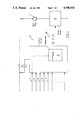
- FIG. 1 shows a block diagram of a control circuit for an electric fuel pump
- FIG. 2 is a flow diagram of the control method for detecting the boundary speed of the engine and for controlling down the speed of the electric fuel pump.
- an electric fuel pump 1 is driven via a control circuit 2.
- the control circuit 2 has input 3 for the speed (n) of the internal combustion engine, and further inputs for the load 4, for the fuel temperature 5 and for the battery voltage 6.
- the plurality of dashed arrows 7 present the possibility for connecting further quantities which influence the fuel requirement.
- the control circuit 2 determines the fuel requirement of the engine in dependence upon these input quantities and controls the electric fuel pump with the aid of a variable pulse duty factor 10 so that the speed of the fuel pump is adapted to the fuel requirement.
- the fuel pump can however also be controlled with the aid of a variable voltage.
- the direct drive of the fuel pump occurs via an end stage 8.
- the essential influencing quantity for the control is constituted by the speed (n) since the fuel requirement increases with higher speeds.
- the speed signal is also directed to a switching component configured as a speed limit-value comparator 9 for a limit speed of the engine.
- the speed limit-value comparator 9 switches and controls the pulse duty factor and thereby the speed and delivery rate of the electric fuel pump to a value beneath the minimum delivery rate for building up the system pressure in the fuel injection system.
- the fuel pump is not completely switched off in this way and, is instead, simply operated below the predetermined minimum speed.
- the speed quantity (n) is compared to determine whether it lies above or below a predetermined limit speed (n max ) for the engine. If the speed is below the limit speed (n max ), the control circuit makes the fuel required available by means of an appropriate speed of the fuel pump with the fuel required being dependent essentially on the speed of the engine under load.
- the delivery rate is dropped below the minimum delivery rate by means of an appropriate programming of the speed dependency.
- the speed gradient of the speed of the engine can be included in the control so that the speed of the fuel pump can be controlled down somewhat before the limit speed is reached so that the limit speed is exceeded only slightly by an overshoot of the control.
- the speed gradient can also again be used for the transition to normal operation or to running up the speed.
Landscapes
- Engineering & Computer Science (AREA)
- Chemical & Material Sciences (AREA)
- Combustion & Propulsion (AREA)
- Mechanical Engineering (AREA)
- General Engineering & Computer Science (AREA)
- Physics & Mathematics (AREA)
- General Physics & Mathematics (AREA)
- Automation & Control Theory (AREA)
- Electrical Control Of Air Or Fuel Supplied To Internal-Combustion Engine (AREA)
Abstract
Description
Claims (4)
Applications Claiming Priority (2)
| Application Number | Priority Date | Filing Date | Title |
|---|---|---|---|
| DE3800177A DE3800177A1 (en) | 1988-01-07 | 1988-01-07 | CONTROL CIRCUIT AND METHOD FOR CONTROLLING THE SPEED OF AN ELECTRIC FUEL PUMP FOR INTERNAL COMBUSTION ENGINES WITH FUEL INJECTION |
| DE3800177 | 1988-01-07 |
Publications (1)
| Publication Number | Publication Date |
|---|---|
| US4940034A true US4940034A (en) | 1990-07-10 |
Family
ID=6344870
Family Applications (1)
| Application Number | Title | Priority Date | Filing Date |
|---|---|---|---|
| US07/294,732 Expired - Lifetime US4940034A (en) | 1988-01-07 | 1989-01-06 | Control circuit and method for controlling the speed of an electric fuel pump for an internal combustion engine equipped with fuel injection |
Country Status (3)
| Country | Link |
|---|---|
| US (1) | US4940034A (en) |
| JP (1) | JPH01224448A (en) |
| DE (1) | DE3800177A1 (en) |
Cited By (19)
| Publication number | Priority date | Publication date | Assignee | Title |
|---|---|---|---|---|
| US5201294A (en) * | 1991-02-27 | 1993-04-13 | Nippondenso Co., Ltd. | Common-rail fuel injection system and related method |
| US5237975A (en) * | 1992-10-27 | 1993-08-24 | Ford Motor Company | Returnless fuel delivery system |
| US5277156A (en) * | 1991-02-27 | 1994-01-11 | Nippondenso Co., Ltd. | Common-rail fuel injection system for an engine |
| US5339785A (en) * | 1992-06-29 | 1994-08-23 | Ford Motor Company | Automotive fuel supply apparatus and control valve |
| US5379741A (en) * | 1993-12-27 | 1995-01-10 | Ford Motor Company | Internal combustion engine fuel system with inverse model control of fuel supply pump |
| US5477833A (en) * | 1991-05-15 | 1995-12-26 | Orbital Engine Company (Australia) Pty. Limited | Fuel system for fuel injected internal combustion engines |
| US5501196A (en) * | 1993-12-28 | 1996-03-26 | Technoflow Tube-Systems Gmbh | Fuel-injection system for motor-vehicle engine |
| US5609140A (en) * | 1994-12-23 | 1997-03-11 | Robert Bosch Gmbh | Fuel supply system for an internal combustion engine |
| WO1997048888A1 (en) * | 1996-06-21 | 1997-12-24 | Outboard Marine Corporation | Programmed break-in mode for two-cycle engine |
| US5740783A (en) * | 1994-12-30 | 1998-04-21 | Walbro Corporation | Engine demand fuel delivery system |
| US5762046A (en) * | 1997-02-06 | 1998-06-09 | Ford Global Technologies, Inc. | Dual speed fuel delivery system |
| US5915363A (en) * | 1996-10-21 | 1999-06-29 | Sanshin Kogyo Kabushiki Kaisha | Fuel supply system for an engine powering an outboard motor |
| US20020152987A1 (en) * | 1999-12-24 | 2002-10-24 | Woolford Richard Albert | Speed limiter |
| US20030024509A1 (en) * | 2001-02-23 | 2003-02-06 | Matusek Steve M. | Method and apparatus for increasing the delivery of fuel to an engine |
| US20060118089A1 (en) * | 2004-12-07 | 2006-06-08 | Hitachi, Ltd. | Controlling apparatus of variable capacity type fuel pump and fuel supply system |
| US20070251501A1 (en) * | 2006-04-26 | 2007-11-01 | Nikki Co., Ltd. | Fuel supply apparatus of engine |
| US20080018271A1 (en) * | 2004-07-05 | 2008-01-24 | Jun Morinaga | Rotation Control Device, Rotation Control Method and Construction Machine |
| US7509945B2 (en) | 2006-03-15 | 2009-03-31 | Chrysler Llc | Fuel pump speed control system |
| US20180112620A1 (en) * | 2015-04-27 | 2018-04-26 | Continental Automotive Gmbh | Method for Regulating a Fuel Delivery System |
Families Citing this family (2)
| Publication number | Priority date | Publication date | Assignee | Title |
|---|---|---|---|---|
| FR2686947A1 (en) * | 1992-02-03 | 1993-08-06 | Walbo Corp | FUEL DELIVERY CIRCUIT FOR INTERNAL COMBUSTION ENGINE. |
| DE4311731A1 (en) * | 1993-04-08 | 1994-10-13 | Bayerische Motoren Werke Ag | Fuel injection system |
Citations (12)
| Publication number | Priority date | Publication date | Assignee | Title |
|---|---|---|---|---|
| US3581839A (en) * | 1969-01-10 | 1971-06-01 | Bendix Corp | Exhaust pollution control circuit |
| US3630177A (en) * | 1968-10-12 | 1971-12-28 | Bosch Gmbh Robert | Speed control for internal combustion engine |
| US3648808A (en) * | 1969-02-05 | 1972-03-14 | Nippon Denso Co | Throttle valve controller device for automobile carburetor |
| US3693603A (en) * | 1969-12-13 | 1972-09-26 | Bosch Gmbh Robert | Control system for fuel control under starting and excessive speed conditions in an internal combustion engine |
| US3817225A (en) * | 1971-03-10 | 1974-06-18 | J Priegel | Electronic carburetion system for low exhaust emmissions of internal combustion engines |
| US3822677A (en) * | 1971-06-30 | 1974-07-09 | Bendix Corp | Electric fuel pump control circuit for intermittent injection electronic fuel control systems |
| US3867918A (en) * | 1971-12-03 | 1975-02-25 | Cav Ltd | Fuel supply systems for internal combustion engines |
| US3967598A (en) * | 1971-06-30 | 1976-07-06 | The Bendix Corporation | Combined electric fuel pump control circuit intermittent injection electronic fuel control systems |
| US4404939A (en) * | 1980-08-09 | 1983-09-20 | Kostal Of America | Electrical circuit for actuation of the relays of a fuel pump |
| US4573440A (en) * | 1982-10-22 | 1986-03-04 | Audi Nsu Auto Union Aktiengesellschaft | Method for limiting the speed of an internal combustion engine in a vehicle and device for same |
| US4791905A (en) * | 1985-04-02 | 1988-12-20 | Nippondenso Co., Ltd. | Control apparatus for a vehicle engine electric fuel pump |
| US4797826A (en) * | 1984-05-31 | 1989-01-10 | Nippondenso Co., Ltd. | Speed control system for vehicles |
Family Cites Families (2)
| Publication number | Priority date | Publication date | Assignee | Title |
|---|---|---|---|---|
| GB1592061A (en) * | 1977-02-10 | 1981-07-01 | Ass Eng Ltd | Speed regulating systems |
| DE3617247C2 (en) * | 1986-05-22 | 1999-03-18 | Bosch Gmbh Robert | Control circuit and method for controlling the speed of an electric fuel pump for internal combustion engines |
-
1988
- 1988-01-07 DE DE3800177A patent/DE3800177A1/en not_active Withdrawn
- 1988-12-16 JP JP63316652A patent/JPH01224448A/en active Pending
-
1989
- 1989-01-06 US US07/294,732 patent/US4940034A/en not_active Expired - Lifetime
Patent Citations (12)
| Publication number | Priority date | Publication date | Assignee | Title |
|---|---|---|---|---|
| US3630177A (en) * | 1968-10-12 | 1971-12-28 | Bosch Gmbh Robert | Speed control for internal combustion engine |
| US3581839A (en) * | 1969-01-10 | 1971-06-01 | Bendix Corp | Exhaust pollution control circuit |
| US3648808A (en) * | 1969-02-05 | 1972-03-14 | Nippon Denso Co | Throttle valve controller device for automobile carburetor |
| US3693603A (en) * | 1969-12-13 | 1972-09-26 | Bosch Gmbh Robert | Control system for fuel control under starting and excessive speed conditions in an internal combustion engine |
| US3817225A (en) * | 1971-03-10 | 1974-06-18 | J Priegel | Electronic carburetion system for low exhaust emmissions of internal combustion engines |
| US3822677A (en) * | 1971-06-30 | 1974-07-09 | Bendix Corp | Electric fuel pump control circuit for intermittent injection electronic fuel control systems |
| US3967598A (en) * | 1971-06-30 | 1976-07-06 | The Bendix Corporation | Combined electric fuel pump control circuit intermittent injection electronic fuel control systems |
| US3867918A (en) * | 1971-12-03 | 1975-02-25 | Cav Ltd | Fuel supply systems for internal combustion engines |
| US4404939A (en) * | 1980-08-09 | 1983-09-20 | Kostal Of America | Electrical circuit for actuation of the relays of a fuel pump |
| US4573440A (en) * | 1982-10-22 | 1986-03-04 | Audi Nsu Auto Union Aktiengesellschaft | Method for limiting the speed of an internal combustion engine in a vehicle and device for same |
| US4797826A (en) * | 1984-05-31 | 1989-01-10 | Nippondenso Co., Ltd. | Speed control system for vehicles |
| US4791905A (en) * | 1985-04-02 | 1988-12-20 | Nippondenso Co., Ltd. | Control apparatus for a vehicle engine electric fuel pump |
Cited By (25)
| Publication number | Priority date | Publication date | Assignee | Title |
|---|---|---|---|---|
| US5201294A (en) * | 1991-02-27 | 1993-04-13 | Nippondenso Co., Ltd. | Common-rail fuel injection system and related method |
| US5277156A (en) * | 1991-02-27 | 1994-01-11 | Nippondenso Co., Ltd. | Common-rail fuel injection system for an engine |
| US5477833A (en) * | 1991-05-15 | 1995-12-26 | Orbital Engine Company (Australia) Pty. Limited | Fuel system for fuel injected internal combustion engines |
| US5339785A (en) * | 1992-06-29 | 1994-08-23 | Ford Motor Company | Automotive fuel supply apparatus and control valve |
| US5237975A (en) * | 1992-10-27 | 1993-08-24 | Ford Motor Company | Returnless fuel delivery system |
| US5379741A (en) * | 1993-12-27 | 1995-01-10 | Ford Motor Company | Internal combustion engine fuel system with inverse model control of fuel supply pump |
| US5501196A (en) * | 1993-12-28 | 1996-03-26 | Technoflow Tube-Systems Gmbh | Fuel-injection system for motor-vehicle engine |
| US5609140A (en) * | 1994-12-23 | 1997-03-11 | Robert Bosch Gmbh | Fuel supply system for an internal combustion engine |
| US5740783A (en) * | 1994-12-30 | 1998-04-21 | Walbro Corporation | Engine demand fuel delivery system |
| WO1997048888A1 (en) * | 1996-06-21 | 1997-12-24 | Outboard Marine Corporation | Programmed break-in mode for two-cycle engine |
| US5915363A (en) * | 1996-10-21 | 1999-06-29 | Sanshin Kogyo Kabushiki Kaisha | Fuel supply system for an engine powering an outboard motor |
| US5762046A (en) * | 1997-02-06 | 1998-06-09 | Ford Global Technologies, Inc. | Dual speed fuel delivery system |
| US20020152987A1 (en) * | 1999-12-24 | 2002-10-24 | Woolford Richard Albert | Speed limiter |
| US6755177B2 (en) * | 1999-12-24 | 2004-06-29 | Orbital Engine Company (Australia) Pty Limited | Speed limiter |
| US20030024509A1 (en) * | 2001-02-23 | 2003-02-06 | Matusek Steve M. | Method and apparatus for increasing the delivery of fuel to an engine |
| US20080018271A1 (en) * | 2004-07-05 | 2008-01-24 | Jun Morinaga | Rotation Control Device, Rotation Control Method and Construction Machine |
| US7619378B2 (en) * | 2004-07-05 | 2009-11-17 | Komatsu Ltd. | Rotation control device, rotation control method and construction machine |
| US20060118089A1 (en) * | 2004-12-07 | 2006-06-08 | Hitachi, Ltd. | Controlling apparatus of variable capacity type fuel pump and fuel supply system |
| US7559313B2 (en) * | 2004-12-07 | 2009-07-14 | Hitachi, Ltd. | Controlling apparatus of variable capacity type fuel pump and fuel supply system |
| US20090241908A1 (en) * | 2004-12-07 | 2009-10-01 | Hitachi, Ltd. | Controlling Apparatus of Variable Capacity Type Fuel Pump and Fuel Supply System |
| US8469007B2 (en) | 2004-12-07 | 2013-06-25 | Hitachi, Ltd. | Controlling apparatus of variable capacity type fuel pump and fuel supply system |
| US7509945B2 (en) | 2006-03-15 | 2009-03-31 | Chrysler Llc | Fuel pump speed control system |
| US20070251501A1 (en) * | 2006-04-26 | 2007-11-01 | Nikki Co., Ltd. | Fuel supply apparatus of engine |
| US20180112620A1 (en) * | 2015-04-27 | 2018-04-26 | Continental Automotive Gmbh | Method for Regulating a Fuel Delivery System |
| US10415495B2 (en) * | 2015-04-27 | 2019-09-17 | Continental Automotive Gmbh | Method for regulating a fuel delivery system |
Also Published As
| Publication number | Publication date |
|---|---|
| JPH01224448A (en) | 1989-09-07 |
| DE3800177A1 (en) | 1989-07-20 |
Similar Documents
| Publication | Publication Date | Title |
|---|---|---|
| US4940034A (en) | Control circuit and method for controlling the speed of an electric fuel pump for an internal combustion engine equipped with fuel injection | |
| US7514889B2 (en) | Steering controlling device | |
| US5048482A (en) | Device for controlling an operating characteristic of an internal combustion engine | |
| US5379178A (en) | Method and device for triggering an electromagnetic consumer | |
| US4709335A (en) | Electronic governor for internal combustion engines | |
| US5050395A (en) | Method of switching an air conditioner of a motor vehicle | |
| US6274993B1 (en) | Motor drive control with excess current period timer resetting | |
| US5218339A (en) | Arrangement for monitoring a consumer in combination with an internal combustion engine and/or a motor vehicle | |
| US5224451A (en) | System for controlling an internal combustion engine | |
| US4467762A (en) | Control apparatus for a fuel metering system | |
| JP3234836B2 (en) | Apparatus for controlling an adjusting device of a vehicle equipped with a drive unit | |
| US5313855A (en) | System for the open-loop control of a motor vehicle | |
| GB2246920A (en) | Drive circuit for an electromagnetic device | |
| US5918579A (en) | Process and device for controlling an internal combustion engine | |
| GB2381881A (en) | Positioning control of an electronic throttle | |
| JPH0350355A (en) | Method and apparatus for limiting running speed | |
| US5510657A (en) | Headlight control circuit of snowmobile | |
| JPS60128955A (en) | Rotary number control method and apparatus of internal combustion engine | |
| JPH0437263B2 (en) | ||
| JPS63503235A (en) | Control circuit and method for controlling the rotation speed of an electric fuel pump of an internal combustion engine | |
| JP2619897B2 (en) | Air-fuel ratio control device | |
| JPS6371435A (en) | Overspeed limiter for automobile | |
| KR100405724B1 (en) | Method For Engine Controlling Of Diesel Vehicle | |
| JPH0246782B2 (en) | ||
| KR100335929B1 (en) | Method for controlling engine rpm in idle |
Legal Events
| Date | Code | Title | Description |
|---|---|---|---|
| AS | Assignment |
Owner name: ROBERT BOSCH GMBH, A CORP. OF FED. REP. OF GERMA Free format text: ASSIGNMENT OF ASSIGNORS INTEREST.;ASSIGNORS:HEIM, HANS;KLEIN, HERMANN-JOSEF;REEL/FRAME:005034/0710;SIGNING DATES FROM 19881223 TO 19890109 |
|
| STCF | Information on status: patent grant |
Free format text: PATENTED CASE |
|
| FEPP | Fee payment procedure |
Free format text: PAYOR NUMBER ASSIGNED (ORIGINAL EVENT CODE: ASPN); ENTITY STATUS OF PATENT OWNER: LARGE ENTITY |
|
| FPAY | Fee payment |
Year of fee payment: 4 |
|
| FEPP | Fee payment procedure |
Free format text: PAYER NUMBER DE-ASSIGNED (ORIGINAL EVENT CODE: RMPN); ENTITY STATUS OF PATENT OWNER: LARGE ENTITY Free format text: PAYOR NUMBER ASSIGNED (ORIGINAL EVENT CODE: ASPN); ENTITY STATUS OF PATENT OWNER: LARGE ENTITY |
|
| FPAY | Fee payment |
Year of fee payment: 8 |
|
| FPAY | Fee payment |
Year of fee payment: 12 |