US4937053A - Crystal growing apparatus - Google Patents
Crystal growing apparatus Download PDFInfo
- Publication number
- US4937053A US4937053A US07/257,766 US25776688A US4937053A US 4937053 A US4937053 A US 4937053A US 25776688 A US25776688 A US 25776688A US 4937053 A US4937053 A US 4937053A
- Authority
- US
- United States
- Prior art keywords
- crucible
- die
- gas
- exterior
- die assembly
- Prior art date
- Legal status (The legal status is an assumption and is not a legal conclusion. Google has not performed a legal analysis and makes no representation as to the accuracy of the status listed.)
- Expired - Lifetime
Links
Images


Classifications
-
- C—CHEMISTRY; METALLURGY
- C30—CRYSTAL GROWTH
- C30B—SINGLE-CRYSTAL GROWTH; UNIDIRECTIONAL SOLIDIFICATION OF EUTECTIC MATERIAL OR UNIDIRECTIONAL DEMIXING OF EUTECTOID MATERIAL; REFINING BY ZONE-MELTING OF MATERIAL; PRODUCTION OF A HOMOGENEOUS POLYCRYSTALLINE MATERIAL WITH DEFINED STRUCTURE; SINGLE CRYSTALS OR HOMOGENEOUS POLYCRYSTALLINE MATERIAL WITH DEFINED STRUCTURE; AFTER-TREATMENT OF SINGLE CRYSTALS OR A HOMOGENEOUS POLYCRYSTALLINE MATERIAL WITH DEFINED STRUCTURE; APPARATUS THEREFOR
- C30B15/00—Single-crystal growth by pulling from a melt, e.g. Czochralski method
- C30B15/34—Edge-defined film-fed crystal-growth using dies or slits
-
- C—CHEMISTRY; METALLURGY
- C30—CRYSTAL GROWTH
- C30B—SINGLE-CRYSTAL GROWTH; UNIDIRECTIONAL SOLIDIFICATION OF EUTECTIC MATERIAL OR UNIDIRECTIONAL DEMIXING OF EUTECTOID MATERIAL; REFINING BY ZONE-MELTING OF MATERIAL; PRODUCTION OF A HOMOGENEOUS POLYCRYSTALLINE MATERIAL WITH DEFINED STRUCTURE; SINGLE CRYSTALS OR HOMOGENEOUS POLYCRYSTALLINE MATERIAL WITH DEFINED STRUCTURE; AFTER-TREATMENT OF SINGLE CRYSTALS OR A HOMOGENEOUS POLYCRYSTALLINE MATERIAL WITH DEFINED STRUCTURE; APPARATUS THEREFOR
- C30B15/00—Single-crystal growth by pulling from a melt, e.g. Czochralski method
-
- C—CHEMISTRY; METALLURGY
- C30—CRYSTAL GROWTH
- C30B—SINGLE-CRYSTAL GROWTH; UNIDIRECTIONAL SOLIDIFICATION OF EUTECTIC MATERIAL OR UNIDIRECTIONAL DEMIXING OF EUTECTOID MATERIAL; REFINING BY ZONE-MELTING OF MATERIAL; PRODUCTION OF A HOMOGENEOUS POLYCRYSTALLINE MATERIAL WITH DEFINED STRUCTURE; SINGLE CRYSTALS OR HOMOGENEOUS POLYCRYSTALLINE MATERIAL WITH DEFINED STRUCTURE; AFTER-TREATMENT OF SINGLE CRYSTALS OR A HOMOGENEOUS POLYCRYSTALLINE MATERIAL WITH DEFINED STRUCTURE; APPARATUS THEREFOR
- C30B29/00—Single crystals or homogeneous polycrystalline material with defined structure characterised by the material or by their shape
- C30B29/60—Single crystals or homogeneous polycrystalline material with defined structure characterised by the material or by their shape characterised by shape
- C30B29/66—Crystals of complex geometrical shape, e.g. tubes, cylinders
-
- Y—GENERAL TAGGING OF NEW TECHNOLOGICAL DEVELOPMENTS; GENERAL TAGGING OF CROSS-SECTIONAL TECHNOLOGIES SPANNING OVER SEVERAL SECTIONS OF THE IPC; TECHNICAL SUBJECTS COVERED BY FORMER USPC CROSS-REFERENCE ART COLLECTIONS [XRACs] AND DIGESTS
- Y10—TECHNICAL SUBJECTS COVERED BY FORMER USPC
- Y10T—TECHNICAL SUBJECTS COVERED BY FORMER US CLASSIFICATION
- Y10T117/00—Single-crystal, oriented-crystal, and epitaxy growth processes; non-coating apparatus therefor
- Y10T117/10—Apparatus
- Y10T117/1024—Apparatus for crystallization from liquid or supercritical state
- Y10T117/1032—Seed pulling
- Y10T117/1036—Seed pulling including solid member shaping means other than seed or product [e.g., EDFG die]
- Y10T117/104—Means for forming a hollow structure [e.g., tube, polygon]
-
- Y—GENERAL TAGGING OF NEW TECHNOLOGICAL DEVELOPMENTS; GENERAL TAGGING OF CROSS-SECTIONAL TECHNOLOGIES SPANNING OVER SEVERAL SECTIONS OF THE IPC; TECHNICAL SUBJECTS COVERED BY FORMER USPC CROSS-REFERENCE ART COLLECTIONS [XRACs] AND DIGESTS
- Y10—TECHNICAL SUBJECTS COVERED BY FORMER USPC
- Y10T—TECHNICAL SUBJECTS COVERED BY FORMER US CLASSIFICATION
- Y10T117/00—Single-crystal, oriented-crystal, and epitaxy growth processes; non-coating apparatus therefor
- Y10T117/10—Apparatus
- Y10T117/1024—Apparatus for crystallization from liquid or supercritical state
- Y10T117/1032—Seed pulling
- Y10T117/1068—Seed pulling including heating or cooling details [e.g., shield configuration]
Definitions
- This invention relates to crystal growing apparatus in general, and more particularly to apparatus adapted to grow crystalline bodies according to the EFG ("Edge-defined, Film-fed Growth”) process.
- EFG Error-defined, Film-fed Growth
- Details of the EFG process and of apparatus for growing crystalline bodies according to the EFG process are described and illustrated in U.S. Pat. No. 3,591,348 issued Jul. 6, 1971 to Harold E. La Belle, Jr. for "Method of Growing Crystalline Materials", and in U.S. Pat. No. 3,687,633 issued aug. 29, 1972 to Harold E. La Belle, Jr. et al. for "Apparatus for Growing Crystalline Bodies from the Melt".
- a capillary-forming die member is placed in association with a melt of liquid source material so that a growth face on the die member is wetted with a liquid film of source material from the melt by capillary action.
- a product crystalline body is then grown by first introducing a seed crystal to the liquid film of source material so that crystal formation is initiated, and then drawing the seed crystal away from the growth face at a controlled rate so that the liquid film of source material remains sandwiched between the growing crystalline body and the growth face of the die member. Since the liquid film of source material on the die's growth face is continuously replenished from the melt by the die's one or more capillaries, continuous crystalline bodies of significant size may be grown from the melt.
- the cross-sectional shape of the product crystalline body is determined by the shape of the growth face of the die member.
- crystalline bodies may be grown which have the shape of a round rod (i.e., where the crystalline body has a cross-sectional shape which is that of a solid circle), a flat ribbon (i.e., where the crystalline body has a cross-sectional shape which is that of a solid rectangle), a hollow tube (i.e., where the crystalline body has an annular cross-section of circular, elliptical or polygonal shape), etc.
- the present invention is directed to apparatus adapted to grow tubular crystalline bodies according to the EFG process.
- control of the atmosphere surrounding the growing crystalline body allows harmful reactive gases to be removed from the area surrounding the growing crystalline body while allowing inert gases, beneficial reactive gases, and/or beneficial doping gases to be introduced to the area surrounding the growing crystalline body.
- control of the temperature of the atmosphere surrounding the growing crystalline body can facilitate proper regulation of the temperature of the growing crystalline body.
- one of the objects of the present invention is to provide novel apparatus for growing tubular crystalline bodies according to the EFG process wherein the apparatus includes means for controlling the atmosphere surrounding the growing crystalline body.
- Another object of the present invention is to provide means for controlling the atmosphere surrounding the growing tubular crystalline body wherein the atmosphere in the zone located outside the growing crystalline body (i.e., the "exterior” zone) can be controlled independently of the atmosphere in the zone located inside the growing crystalline body (i.e., the "interior” zone).
- the apparatus has at least one exterior passage and at least one interior passage formed in its crucible-die assembly and associated parts, whereby gases introduced into the at least one exterior passage will be delivered to the zone located outside the growing crystalline body (i.e. the "exterior" zone) adjacent to the growth face on the die member, and gases introduced into the at least one interior passage will be delivered to the zone located inside of the hollow crystalline body (i.e., the "interior" zone) adjacent to the growth face on the die member, whereby the atmosphere in each of the zones may be separately controlled.
- tube and tubular are to be construed in a generic sense to include elongate hollow bodies having a circular, polygonal or other--e.g. elliptical--cross-sectional shape.
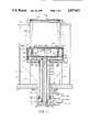
- FIG. 1 is a sectional view of novel apparatus for growing tubular crystalline bodies according to the EFG process, wherein the apparatus incorporates a preferred embodiment of the present invention
- FIG. 2 is a top plan view of the crucible-die assembly shown in FIG. 1;
- FIG. 2A is a partial sectional view of the crucible-die assembly shown in FIGS. 1 and 2;
- FIG. 3 is a top plan view of the interior gas flow manifold shown in FIG. 1;
- FIG. 4 is a sectional view taken along line 4--4 of FIG. 3;
- FIG. 5 is a top plan view of the exterior gas flow manifold shown in FIG. 1;
- FIG. 6 is a sectional view taken along line 6--6 of FIG. 5.
- FIG. 1 there is shown novel apparatus for growing tubular crystalline bodies from a melt.
- the apparatus of FIG. 1 also includes associated apparatus such as heating coils, inner and outer after heater assemblies, insulation, etc. such as is normally found in a crystal growing furnace of the type disclosed in U.S. Pat. No. 4,440,728.
- associated apparatus such as heating coils, inner and outer after heater assemblies, insulation, etc.
- Such associated apparatus has now been omitted to facilitate understanding of the present invention.
- the apparatus of FIG. 1 comprises a growth chamber 100 defined by a side wall 105, a top cover 110 and a chamber base 115.
- Top cover 110 has a center hole 120 formed therein, and chamber base 115 has a center hole 125 formed therein.
- Aperture 120 is axially aligned with aperture 125
- Top aperture 120 preferably has a shape which, when looked at in plan view, is identical to the cross-sectional shape of the hollow crystalline body which is being grown in the apparatus, so that the hollow crystalline body issuing from the melt can pass through aperture 120 and make a reasonably close fit with the inner edges of top cover 110 which define its aperture 120, as will hereinafter be described in further detail
- Center hole 125 preferably has a shape which, when looked at in plan view, is circular.
- the growth chamber's side wall 105, top cover 110 and chamber base 115 are fastened to one another so as to be as airtight as possible at their points of intersection, whereby center holes 120 and 125 constitute the portals into and out of growth chamber 100.
- Growth chamber 100 is formed out of those materials well known to those skilled in the art that are compatible with and do not react with the material of the hollow crystalline body that is being grown, e.g. side wall 105 is made of quartz, and top cover 110 and chamber base 115 are made of stainless steel where the growing crystalline body consists of silicon.
- Crucible-die assembly 200 is disposed within growth chamber 100. Looking next at FIGS. 1, 2 and 2A, crucible-die assembly 200 is similar to crucible-die assemblies well known in the art, but differs therefrom in specific features that are hereinafter described and illustrated in detail. More specifically, crucible-die assembly 200 comprises a central chamber 205 for receiving a melt 210 of the source material which is to be grown, a growth face 215 formed at the top of the crucible-die assembly, a capillary 216 that intersects growth face 215, and a plurality of capillary feed slots 220 formed in the walls of the crucible-die assembly for wetting growth face 215 with a liquid film of source material from melt 210.
- growth face 215 actually comprises a pair of end surfaces or edges 215' and 215' separated by a capillary opening 216. It is to be understood that liquid source material (i.e., the "melt”) is transported via feed slots 220 and capillary 216 to growth face 215 by capillary action.
- liquid source material i.e., the "melt”
- Crucible-die assembly 200 has its growth face 215 formed as a series of six abutting surfaces 215A, 215B, 215C, etc. (see FIG. 2), whereby a hollow tubular crystal of a hexagonal nature will be grown.
- Crucible-die assembly 200 has a pair of top surfaces disposed on either side of, and slightly below, growth face 215: an exterior top surface 225 (actually formed by six co-planar surfaces 225A, 225B, 225C, etc.) resides alongside growth face 215 exterior to the growth face; and an interior top surface 230 resides alongside growth face 215 interior to the growth face. As best seen in FIG. 1, top surfaces 225 and 230 sit below growth face 215 but sit above the top surface of melt 210.
- Crucible-die assembly 200 also includes a flat bottom surface 235.
- Crucible-die assembly 200 is formed out of materials well known to those skilled in the art, e.g. graphite.
- Crucible-die assembly 200 departs from conventional crucible-die assemblies in that it includes a plurality of exterior vertical passages 240 which extend between the crucible-die assembly's exterior top surface 225 and its bottom surface 235, and a plurality of interior vertical passages 245 which extend between the crucible-die assembly's interior top surface 230 and its bottom surface 235.
- Crucible-die assembly 200 sits on an interior gas manifold plate 300.
- interior gas manifold plate 300 comprises a disk or platter which has a flat top surface 305 and a flat bottom surface 310.
- Interior gas manifold 300 has a plurality of vertical passages 315 which extend between its top surface 305 and its bottom surface 310. Vertical passages 315 are sized and positioned so that they may be aligned with exterior vertical passages 240 formed in crucible-die assembly 200 when interior gas manifold plate 300 is positioned against the bottom surface of the crucible-die assembly, as will hereinafter be described in further detail.
- Interior gas manifold plate 300 also includes a central aperture 320 which extends between the plate's top surface 305 and its bottom surface 310.
- a plurality of surface grooves 325 are formed in top surface 305 of plate 300.
- Surface grooves 325 communicate with the plate's central aperture 320 and radiate outwardly so as to communicate with a hexagonally-shaped surface groove 330 also formed in the plate's top surface 305.
- Hexagonal surface groove 330 is sized and positioned so that it may be aligned with interior vertical passages 245 formed in crucible-die assembly 200 when interior gas manifold plate 300 is positioned against the bottom surface of the crucible-die assembly, as will hereinafter be described in further detail.
- Interior gas manifold plate is formed out of materials well known to those skilled in the art, e.g. graphite.
- Exterior gas manifold plate 400 comprises a disk or platter having a flat top surface 405 and a flat bottom surface 410. Exterior gas manifold plate 400 has a central aperture 420 which extends between its top surface 405 and its bottom surface 410. A plurality of surface grooves 425 are formed in top surface 405 of plate 400. Surface grooves 425 communicate with the plate's central aperture 420 and radiate outwardly so as to communicate with a circular surface groove 430 (FIG. 5) also formed in the plate's top surface 405.
- Circular surface groove 430 is sized and positioned so that it may be aligned with vertical passages 315 formed in interior gas manifold plate 300 when exterior gas manifold plate 400 is positioned against the bottom surface of interior gas manifold plate 300, as will hereinafter be described in further detail.
- Exterior gas manifold plate 400 is formed out of materials well known to those skilled in the art, e.g. graphite.
- Crucible-die assembly 200, interior gas manifold plate 300 and exterior gas manifold plate 400 are assembled together in the manner shown in FIG. 1, so that top surface 305 of interior gas manifold plate 300 is positioned against bottom surface 235 of crucible-die assembly 200, with vertical passages 315 of the interior gas manifold plate being aligned with exterior vertical passages 240 of the crucible-die assembly, and with surface grooves 325 of the interior gas manifold plate adjoining bottom surface 235 of the crucible-die assembly whereby bottom surface 235 forms a ceiling for surface grooves 325, and with surface grooves 325 of the interior gas manifold plate communicating with interior vertical passages 245 formed in the crucible-die assembly
- top surface 405 of exterior gas manifold plate 400 is positioned against bottom surface 310 of interior gas manifold plate 300 so that central aperture 420 of the exterior gas manifold plate is axially aligned with central aperture 320 of interior gas manifold plate, and so that surface grooves 425 of
- an interior gas feed tube 500 is attached to interior gas manifold plate 300 so that the feed tube's top end 505 forms an airtight fit with the walls of the manifold which define that manifold's central aperture 320.
- Interior gas feed tube 500 is attached to interior gas manifold plate 300 in the manner shown in FIG. 1 so that the feed tube's interior communicates with radial surface grooves 325 formed in interior manifold plate 300, whereby gases passed into the feed tube's lower end 510 will flow first into surface grooves 325 formed in the interior gas manifold plate and thereafter into internal vertical passages 245 formed in crucible-die assembly 200.
- Interior gas feed tube 500 is formed out of materials well known to those skilled in the art, e.g. graphite.
- An exterior gas feed tube 600 is positioned concentrically around interior gas feed tube 500 and attached to exterior gas manifold plate 400 so that the exterior gas feed tube's top end 605 forms an airtight fit with the walls of the manifold which define that manifold's central aperture 420. This arrangement results in the creation of a chamber 607 between the concentric walls of the interior and exterior gas feed tubes. Exterior gas feed tube 600 is attached to exterior gas manifold plate 400 in the manner shown in FIG.
- Exterior gas feed tube 600 is formed out of materials well known to those skilled in the art, e.g. graphite.
- interior gas feed tube 500 and exterior gas feed tube 600 extend downward through bottom central aperture 125 formed in chamber base 115 and contact a gas fitting 700.
- Gas fitting 700 is disposed about bottom central aperture 125 and forms an airtight fit with chamber base 115.
- Gas fitting 700 is equipped with a central aperture 705, a first interior wall 710, a second interior wall 715, a first port 720, a second port 725 and a third port 730.
- Interior gas feed tube 500 is attached to gas fitting 700 so that the tube's second end 510 forms an airtight fit with an O-ring seal 735 disposed in a groove in first wall 710, whereby gases entering the fitting's first port 720 will be directed into the interior of interior gas feed tube 500.
- Exterior gas feed tube 600 is attached to gas fitting 700 so that the tube's second end 610 forms an airtight fit with an O-ring seal 740 disposed in a groove in second wall 715, whereby gases entering the fitting's second port 725 will be directed into the chamber 607 formed between the concentric interior and exterior gas feed tubes.
- the outside dimension of exterior gas feed tube 600 is sized to be less than the dimension of bottom central aperture 125 of chamber base 115 and also less than the width of the gas fitting's central aperture 705, gases entering the fitting's third port 730 will be directed into the interior of growth chamber 100 but will be kept exterior to exterior gas feed tube 600 and crucible-die assembly 200.
- Gas fitting 700 is formed out of materials well known to those skilled in the art, e.g. stainless steel.
- gas directing means 800 disposed about the top end of crucible-die assembly 200. More specifically, gas directing means 800 comprises an exterior gas deflector 805 which sits atop the crucible-die assembly's exterior top surface 225 and which directs gases exiting from the top of exterior vertical passages 240 toward the crucible-die assembly's growth face 215, and an interior gas deflector 810 which sits atop the crucible-die assembly's interior top surface 230 and which directs gases exiting from the top of interior vertical passages 245 toward the crucible-die assembly's growth face 215. Exterior gas deflector 805 and interior gas deflector 810 are formed out of materials well known to those skilled in the art, e.g. graphite.
- gases directed into first port 720 of gas fitting 700 will make their way along the interior of interior gas feed tube 500, along surface grooves 325 formed in interior gas manifold plate 300, into interior vertical passages 245 formed in crucible-die assembly 200 and thereafter be deflected by interior gas deflector 810 against the interior surface of the hollow crystalline body issuing from die growth face 215.
- gases directed into second port 725 of gas fitting 700 will make their way along chamber 607 formed between the concentric gas feed tubes 500 and 600, along surface grooves 425 formed in exterior gas manifold plate 400, into vertical passages 315 formed in interior gas manifold plate 300, along exterior vertical passages 240 formed in crucible-die assembly 200 and thereafter be deflected by exterior gas deflector 805 against the exterior surface of the hollow crystalline body issuing from die growth face 215.
- gases directed into third port 730 of gas fitting 700 will make their way through bottom central aperture 125 formed in chamber base 115 and into growth chamber 100.
- top central aperture 120 of the growth chamber's top cover 110 is sized so as to be slightly larger than the crystalline body issuing from the melt, gases introduced into growth chamber 100 via the gas fitting's second port 725 and third port 730 will be able to escape from the growth chamber by passing through the small gap existing between the issuing crystalline body 900 and top cover 110. It is also to be appreciated that inasmuch as the seed holder 905 set at the top of the issuing hollow crystalline body 900 is not airtight, gases introduced into the interior of the growing crystalline body 900 via first port 720 will be able to escape from the interior of the issuing hollow crystalline body by passing through seed holder 905.
- port 720 might be used to introduce argon into the zone located inside the growing crystalline body (i.e., the "interior" zone), where the argon is introduced at a temperature of approximately 30 degrees C.
- port 725 might be used to introduce argon into the zone located outside the growing crystalline body (i.e., the "exterior" zone), where the argon is introduced at a temperature of approximately 30 degrees C. and is introduced at a rate of approximately 12000 cubic centimeters per minute; and port 730 might be used to introduce argon into growth chamber 100, where the gas is introduced at a temperature of approximately 30 degrees C. and is introduced at a rate of approximately 16000 cubic centimeters per minute.
- the temperature of the growth face of the die is maintained at a temperature of between about 1410 and 1450 degrees C. during the growth procedure.
- the tubular crystalline product has a wall thickness of about 0.4 millimeters and its composition essentially comprises silicon.
- inert argon gas was described as being introduced into ports 720 and 725 for the purpose of purging the growth zone of any harmful reactive gases which might be present, and inert argon gas was described as being introduced into port 730 for the purpose of providing an inert atmosphere within growth chamber 100
- beneficial reactive gases such as oxygen, carbon monoxide, carbon dioxide, methane, etc. might be introduced into one or both of the ports 720 and 725 so as to introduce them into the growth zone, or port 730 so as to introduce them into growth chamber 100
- beneficial doping gases such as boron fluoride, phosphine, etc. might be introduced into one or both of the ports 720 and 725 so as to introduce them into the growth zone, or port 730 so as to introduce them into growth chamber 100.
- crucible-die assembly 200 could be formed so as to have more or less than the six abutting die surfaces 215A, 215B, 215C, etc. and the six co-planar exterior surfaces 225A, 225B, 225C, etc. described above, whereby a crystalline body of a different cross-sectional shape could be grown, e.g. crucible-die assembly 200 could be formed so as to have nine abutting die surfaces 215A, 215B, 215C, etc. and nine co-planar surfaces 225A, 225B, 225C, etc., whereby crystalline bodies of a nonagonal cross-section could be grown.
- the vertical passages 240 and 245 carrying the gases inlet at ports 720 and 725, respectively, extend through the full height of the crucible-die assembly 200 before opening on faces 225 and 230.
- Such an arrangement is generally desirable since it allows the gases moving through passages 240 and 245 to pick up the heat of the melt and facilitates deploying the gases at the growth zone at the same temperature as the melt.
- passages 240 and 245 In this case one might place a layer of insulation around passages 240 and 245 to insulate the gases flowing through these passages from the temperature of the melt or, alternatively, one might even alter the positioning of passages 240 and 245 so that they extend horizontally through the crucible-die assembly, parallel to surfaces 225 and 230; such an arrangement could reduce the exposure of the gases passing through these passages from the heat of the crucible, although it would necessitate replacing the present means used to transport the gases from inlet ports 720 and 725 to passages 240 and 245 with some alternate means.
- the novel apparatus for growing tubular crystalline bodies includes means for controlling the atmosphere surrounding the growing crystalline body.
- harmful reactive gases can be removed from the area surrounding the growing crystalline body and inert gases, beneficial reactive gases and/or beneficial doping gases can be introduced to the area surrounding the growing crystalline body.
- beneficial reactive gases and/or beneficial doping gases can be introduced to the area surrounding the growing crystalline body.
- by controlling the temperature of the atmosphere surrounding the growing crystalline body proper regulation of the temperature of the growing crystalline body can be facilitated.
- Another advantage of using the present invention is that means are provided for controlling the atmosphere surrounding the growing tubular crystalline body wherein the atmosphere in the zone located outside the growing crystalline body (i.e., the "exterior" zone) can be controlled independently of the atmosphere in the zone located inside the growing crystalline body (i.e., the "interior” zone).
- the exterior of the product crystalline body can be subjected to different growth conditions than the interior of the product crystalline body, if desired.
- Another advantage of the present invention is that inasmuch as exterior vertical passages 240 and interior vertical passages 245 pass through the full height of the crucible-die assembly prior to opening adjacent to the crucible-die assembly's growth face, gases flowing upward through these passages to the growth face are allowed an opportunity to reach temperatures very close to that of the melt.
Landscapes
- Chemical & Material Sciences (AREA)
- Engineering & Computer Science (AREA)
- Crystallography & Structural Chemistry (AREA)
- Materials Engineering (AREA)
- Metallurgy (AREA)
- Organic Chemistry (AREA)
- Physics & Mathematics (AREA)
- Geometry (AREA)
- Crystals, And After-Treatments Of Crystals (AREA)
Abstract
Description
Claims (26)
Priority Applications (1)
| Application Number | Priority Date | Filing Date | Title |
|---|---|---|---|
| US07/257,766 US4937053A (en) | 1987-03-27 | 1988-09-30 | Crystal growing apparatus |
Applications Claiming Priority (2)
| Application Number | Priority Date | Filing Date | Title |
|---|---|---|---|
| US3139287A | 1987-03-27 | 1987-03-27 | |
| US07/257,766 US4937053A (en) | 1987-03-27 | 1988-09-30 | Crystal growing apparatus |
Related Parent Applications (1)
| Application Number | Title | Priority Date | Filing Date |
|---|---|---|---|
| US3139287A Continuation | 1987-03-27 | 1987-03-27 |
Publications (1)
| Publication Number | Publication Date |
|---|---|
| US4937053A true US4937053A (en) | 1990-06-26 |
Family
ID=26707186
Family Applications (1)
| Application Number | Title | Priority Date | Filing Date |
|---|---|---|---|
| US07/257,766 Expired - Lifetime US4937053A (en) | 1987-03-27 | 1988-09-30 | Crystal growing apparatus |
Country Status (1)
| Country | Link |
|---|---|
| US (1) | US4937053A (en) |
Cited By (14)
| Publication number | Priority date | Publication date | Assignee | Title |
|---|---|---|---|---|
| WO1992001091A1 (en) * | 1990-07-10 | 1992-01-23 | Saphikon, Inc. | Apparatus for growing hollow crystalline bodies from the melt |
| US5370078A (en) * | 1992-12-01 | 1994-12-06 | Wisconsin Alumni Research Foundation | Method and apparatus for crystal growth with shape and segregation control |
| EP0785039A2 (en) | 1996-01-18 | 1997-07-23 | General Electric Company | Solidification of an article extension from a melt using a ceramic mold |
| US5673744A (en) * | 1996-06-27 | 1997-10-07 | General Electric Company | Method for forming an article extension by melting of a mandrel in a ceramic mold |
| US5673745A (en) * | 1996-06-27 | 1997-10-07 | General Electric Company | Method for forming an article extension by melting of an alloy preform in a ceramic mold |
| US5676191A (en) * | 1996-06-27 | 1997-10-14 | General Electric Company | Solidification of an article extension from a melt using an integral mandrel and ceramic mold |
| US5743322A (en) * | 1996-06-27 | 1998-04-28 | General Electric Company | Method for forming an article extension by casting using a ceramic mold |
| US5778960A (en) * | 1995-10-02 | 1998-07-14 | General Electric Company | Method for providing an extension on an end of an article |
| US5863326A (en) * | 1996-07-03 | 1999-01-26 | Cermet, Inc. | Pressurized skull crucible for crystal growth using the Czochralski technique |
| US5900060A (en) * | 1996-07-03 | 1999-05-04 | Cermet, Inc. | Pressurized skull crucible apparatus for crystal growth and related system and methods |
| US20040151598A1 (en) * | 2002-02-19 | 2004-08-05 | Vapore, Inc. | Capillary pumps for vaporization of liquids |
| US20090136731A1 (en) * | 2007-10-23 | 2009-05-28 | Saint-Gobain Ceramics & Plastics, Inc. | Scintillator crystals and methods of forming |
| US20090220222A1 (en) * | 2005-05-16 | 2009-09-03 | Vapore, Inc. | Capillary force vaporizers |
| US20110210458A1 (en) * | 2006-05-15 | 2011-09-01 | Vapore, Inc. | Thin Film Capillary Vaporization: Device and Methods |
Citations (11)
| Publication number | Priority date | Publication date | Assignee | Title |
|---|---|---|---|---|
| US3265469A (en) * | 1964-09-21 | 1966-08-09 | Gen Electric | Crystal growing apparatus |
| US3701636A (en) * | 1970-09-23 | 1972-10-31 | Tyco Laboratories Inc | Crystal growing apparatus |
| US3846082A (en) * | 1971-11-08 | 1974-11-05 | Tyco Laboratories Inc | Production of crystalline bodies of complex geometries |
| US3953174A (en) * | 1975-03-17 | 1976-04-27 | Tyco Laboratories, Inc. | Apparatus for growing crystalline bodies from the melt |
| US4118197A (en) * | 1977-01-24 | 1978-10-03 | Mobil Tyco Solar Energy Corp. | Cartridge and furnace for crystal growth |
| US4230674A (en) * | 1976-12-27 | 1980-10-28 | Mobil Tyco Solar Energy Corporation | Crucible-die assemblies for growing crystalline bodies of selected shapes |
| US4415401A (en) * | 1980-03-10 | 1983-11-15 | Mobil Solar Energy Corporation | Control of atmosphere surrounding crystal growth zone |
| US4440728A (en) * | 1981-08-03 | 1984-04-03 | Mobil Solar Energy Corporation | Apparatus for growing tubular crystalline bodies |
| US4443411A (en) * | 1980-12-15 | 1984-04-17 | Mobil Solar Energy Corporation | Apparatus for controlling the atmosphere surrounding a crystal growth zone |
| US4544528A (en) * | 1981-08-03 | 1985-10-01 | Mobil Solar Energy Corporation | Apparatus for growing tubular crystalline bodies |
| US4647437A (en) * | 1983-05-19 | 1987-03-03 | Mobil Solar Energy Corporation | Apparatus for and method of making crystalline bodies |
-
1988
- 1988-09-30 US US07/257,766 patent/US4937053A/en not_active Expired - Lifetime
Patent Citations (11)
| Publication number | Priority date | Publication date | Assignee | Title |
|---|---|---|---|---|
| US3265469A (en) * | 1964-09-21 | 1966-08-09 | Gen Electric | Crystal growing apparatus |
| US3701636A (en) * | 1970-09-23 | 1972-10-31 | Tyco Laboratories Inc | Crystal growing apparatus |
| US3846082A (en) * | 1971-11-08 | 1974-11-05 | Tyco Laboratories Inc | Production of crystalline bodies of complex geometries |
| US3953174A (en) * | 1975-03-17 | 1976-04-27 | Tyco Laboratories, Inc. | Apparatus for growing crystalline bodies from the melt |
| US4230674A (en) * | 1976-12-27 | 1980-10-28 | Mobil Tyco Solar Energy Corporation | Crucible-die assemblies for growing crystalline bodies of selected shapes |
| US4118197A (en) * | 1977-01-24 | 1978-10-03 | Mobil Tyco Solar Energy Corp. | Cartridge and furnace for crystal growth |
| US4415401A (en) * | 1980-03-10 | 1983-11-15 | Mobil Solar Energy Corporation | Control of atmosphere surrounding crystal growth zone |
| US4443411A (en) * | 1980-12-15 | 1984-04-17 | Mobil Solar Energy Corporation | Apparatus for controlling the atmosphere surrounding a crystal growth zone |
| US4440728A (en) * | 1981-08-03 | 1984-04-03 | Mobil Solar Energy Corporation | Apparatus for growing tubular crystalline bodies |
| US4544528A (en) * | 1981-08-03 | 1985-10-01 | Mobil Solar Energy Corporation | Apparatus for growing tubular crystalline bodies |
| US4647437A (en) * | 1983-05-19 | 1987-03-03 | Mobil Solar Energy Corporation | Apparatus for and method of making crystalline bodies |
Cited By (18)
| Publication number | Priority date | Publication date | Assignee | Title |
|---|---|---|---|---|
| US5398640A (en) * | 1990-07-10 | 1995-03-21 | Saphikon, Inc. | Apparatus for growing hollow crystalline bodies from the melt |
| WO1992001091A1 (en) * | 1990-07-10 | 1992-01-23 | Saphikon, Inc. | Apparatus for growing hollow crystalline bodies from the melt |
| US5370078A (en) * | 1992-12-01 | 1994-12-06 | Wisconsin Alumni Research Foundation | Method and apparatus for crystal growth with shape and segregation control |
| US5778960A (en) * | 1995-10-02 | 1998-07-14 | General Electric Company | Method for providing an extension on an end of an article |
| EP0785039A2 (en) | 1996-01-18 | 1997-07-23 | General Electric Company | Solidification of an article extension from a melt using a ceramic mold |
| US5904201A (en) * | 1996-01-18 | 1999-05-18 | General Electric Company | Solidification of an article extension from a melt using a ceramic mold |
| US5673744A (en) * | 1996-06-27 | 1997-10-07 | General Electric Company | Method for forming an article extension by melting of a mandrel in a ceramic mold |
| US5743322A (en) * | 1996-06-27 | 1998-04-28 | General Electric Company | Method for forming an article extension by casting using a ceramic mold |
| US5676191A (en) * | 1996-06-27 | 1997-10-14 | General Electric Company | Solidification of an article extension from a melt using an integral mandrel and ceramic mold |
| US5673745A (en) * | 1996-06-27 | 1997-10-07 | General Electric Company | Method for forming an article extension by melting of an alloy preform in a ceramic mold |
| US5863326A (en) * | 1996-07-03 | 1999-01-26 | Cermet, Inc. | Pressurized skull crucible for crystal growth using the Czochralski technique |
| US5900060A (en) * | 1996-07-03 | 1999-05-04 | Cermet, Inc. | Pressurized skull crucible apparatus for crystal growth and related system and methods |
| US20040151598A1 (en) * | 2002-02-19 | 2004-08-05 | Vapore, Inc. | Capillary pumps for vaporization of liquids |
| US7431570B2 (en) * | 2002-02-19 | 2008-10-07 | Vapore, Inc. | Capillary pumps for vaporization of liquids |
| US20090220222A1 (en) * | 2005-05-16 | 2009-09-03 | Vapore, Inc. | Capillary force vaporizers |
| US20110210458A1 (en) * | 2006-05-15 | 2011-09-01 | Vapore, Inc. | Thin Film Capillary Vaporization: Device and Methods |
| US9746194B2 (en) | 2006-05-15 | 2017-08-29 | Vapore, Llc | Thin film capillary vaporization: device and methods |
| US20090136731A1 (en) * | 2007-10-23 | 2009-05-28 | Saint-Gobain Ceramics & Plastics, Inc. | Scintillator crystals and methods of forming |
Similar Documents
| Publication | Publication Date | Title |
|---|---|---|
| US4937053A (en) | Crystal growing apparatus | |
| JP5421229B2 (en) | Single crucible and effusion source using such crucible | |
| US5229082A (en) | Melt replenishment system for dendritic web growth | |
| US3953174A (en) | Apparatus for growing crystalline bodies from the melt | |
| US3915662A (en) | Method of growing mono crystalline tubular bodies from the melt | |
| JPS58104093A (en) | Method and device for controlling atomosphere surrounding crystal growth zone | |
| US4440728A (en) | Apparatus for growing tubular crystalline bodies | |
| EP0309540B1 (en) | An apparatus and process for edge-defined, film-fed crystal growth | |
| US4544528A (en) | Apparatus for growing tubular crystalline bodies | |
| CA1081586A (en) | Method and apparatus for forming silicon crystalline bodies | |
| EP0612867A1 (en) | Inert gas rectifying/blowing apparatus for single crystal pulling device | |
| US3701636A (en) | Crystal growing apparatus | |
| US6367288B1 (en) | Method and apparatus for preventing burner-hole build-up in fused silica processes | |
| US5820649A (en) | Method of and apparatus for continuously producing a solid material | |
| JPH0634273A (en) | Method and device for supplying smelting furnace with reaction gas | |
| US4000977A (en) | Apparatus for producing monocrystals by the verneuil technique | |
| US4233270A (en) | Process and device for growing crystal | |
| JPS63256593A (en) | Apparatus for growing single crystal | |
| JPH0523580Y2 (en) | ||
| CN117779179B (en) | Single crystal growth device and single crystal growth method | |
| JPS6484717A (en) | Semiconductor thin film vapor growth apparatus | |
| US3697228A (en) | Apparatus for growing crystals in plate form | |
| JPS63176388A (en) | Apparatus for pulling up single crystal | |
| GB2155806A (en) | Apparatus for replenishing a melt | |
| JPS63222090A (en) | Apparatus for growing single crystal |
Legal Events
| Date | Code | Title | Description |
|---|---|---|---|
| STCF | Information on status: patent grant |
Free format text: PATENTED CASE |
|
| CC | Certificate of correction | ||
| CC | Certificate of correction | ||
| FEPP | Fee payment procedure |
Free format text: PAYOR NUMBER ASSIGNED (ORIGINAL EVENT CODE: ASPN); ENTITY STATUS OF PATENT OWNER: LARGE ENTITY |
|
| FPAY | Fee payment |
Year of fee payment: 4 |
|
| AS | Assignment |
Owner name: ASE AMERICAS, INC., MASSACHUSETTS Free format text: CHANGE OF NAME;ASSIGNOR:MOBIL SOLAR ENERGY CORPORATION;REEL/FRAME:007465/0206 Effective date: 19940801 |
|
| FPAY | Fee payment |
Year of fee payment: 8 |
|
| FPAY | Fee payment |
Year of fee payment: 12 |
|
| REMI | Maintenance fee reminder mailed | ||
| AS | Assignment |
Owner name: RWE SCHOTT SOLAR INC., MASSACHUSETTS Free format text: CHANGE OF NAME;ASSIGNOR:ASE AMERICAS, INC.;REEL/FRAME:014210/0339 Effective date: 20030103 |
|
| AS | Assignment |
Owner name: SCHOTT SOLAR, INC., MASSACHUSETTS Free format text: CHANGE OF NAME;ASSIGNOR:RWE SCHOTT SOLAR INC.;REEL/FRAME:018207/0081 Effective date: 20060331 |