US492964A - Machine for cutting into strips and reeling or winding paper - Google Patents
Machine for cutting into strips and reeling or winding paper Download PDFInfo
- Publication number
- US492964A US492964A US492964DA US492964A US 492964 A US492964 A US 492964A US 492964D A US492964D A US 492964DA US 492964 A US492964 A US 492964A
- Authority
- US
- United States
- Prior art keywords
- strips
- cutting
- cylinder
- machine
- roll
- Prior art date
- Legal status (The legal status is an assumption and is not a legal conclusion. Google has not performed a legal analysis and makes no representation as to the accuracy of the status listed.)
- Expired - Lifetime
Links
- 238000004804 winding Methods 0.000 title description 48
- 239000000123 paper Substances 0.000 description 34
- 239000000463 material Substances 0.000 description 14
- 239000000203 mixture Substances 0.000 description 6
- 230000013707 sensory perception of sound Effects 0.000 description 6
- 239000011111 cardboard Substances 0.000 description 4
- 239000004744 fabric Substances 0.000 description 4
- 241000256844 Apis mellifera Species 0.000 description 2
- 241000735495 Erica <angiosperm> Species 0.000 description 2
- -1 Gard-Board Substances 0.000 description 2
- 229910000831 Steel Inorganic materials 0.000 description 2
- 238000010276 construction Methods 0.000 description 2
- 230000000694 effects Effects 0.000 description 2
- 230000036633 rest Effects 0.000 description 2
- 230000002441 reversible Effects 0.000 description 2
- 238000000926 separation method Methods 0.000 description 2
- 239000007787 solid Substances 0.000 description 2
- 239000010959 steel Substances 0.000 description 2
Images


Classifications
-
- B—PERFORMING OPERATIONS; TRANSPORTING
- B65—CONVEYING; PACKING; STORING; HANDLING THIN OR FILAMENTARY MATERIAL
- B65H—HANDLING THIN OR FILAMENTARY MATERIAL, e.g. SHEETS, WEBS, CABLES
- B65H35/00—Delivering articles from cutting or line-perforating machines; Article or web delivery apparatus incorporating cutting or line-perforating devices, e.g. adhesive tape dispensers
- B65H35/02—Delivering articles from cutting or line-perforating machines; Article or web delivery apparatus incorporating cutting or line-perforating devices, e.g. adhesive tape dispensers from or with longitudinal slitters or perforators
Definitions
- Fig. 4 is an enlarged detail of one of the small cutter shafts and a portion of the larger cutter shaft which co-operates therewith.
- Fig.5 is a sectional detail of the large cutter shaft, illustrating the manner in which it is supported at its ends.
- Fig. 6 is a sectional detail on the line as, w of Fig. 1, showing the arrangement of the gears inside the framework at one end of the machine.
- Fig. 7 is a plan showing the swinging pressure roll frame at the top of the machine.
- Fig. 8 is a sectional detail on the line y, y of Fig. 1, showing the arrangement of the journal boxes of the small cutter shafts.
- My invention relates to an improved machine for cutting into strips paper, card-board, cloth, and other similar material, and reeling or winding it up into rolls, and has for its object to perform these operations in a more perfect and satisfactory manner than heretofore.
- A representsthe framework of the machine, outside of which upon a suitable stud formed at the end of a tie-bar 10 is mounted the driving pulley B, upon the hub of which is a pinion O which meshes with and drives the gear Dsecured to the end of a friction feed or winding cylinder E, consisting of a tubular shell or core-shaft 12, over $erial No. 433,921- (No model.)
- the cutting disks or are made reversible in order that both edges may be utilized, and the rings or collars b may be of different widths, and may be so arranged in connections with the disks 0 as to cut a series of strips of different widths at the same time.
- the cylinder E is provided at one end with a supporting shaft 15,the journal of which runs in a box or bearing in one side of the framework, while the opposite end of the cylinder E is supported by and runs upon a sliding center pin e, which enters a conical recess in a plugfdriven into the end of the core-shaft 12, as seen in Fig. 5, said center pin 6 being held in position by a screw g, Fig.
- a shoulder Z, Figs. 4 and 5 At one end of the cylinder E is a shoulder Z, Figs. 4 and 5, and at the opposite end a threaded collar or nut m of the same diameter as the rings and disks, and provided with holes nfor a wrench, whereby said nut may be screwed over one end of the core-shaft 12 tightly up against the last ring of the series to clamp the rings and cutters upon thecyl- 'inder.
- a gear 1) which meshes with and drives the gears q, r, 8, Figs. 1 and 6, fasten the shafts G, which carry the small circular knives-or cutting disks 0 secured to their shafts by means of screws 25, whereby they may be adjusted longitudinally on said shafts to correspond to the positions of the large cutting disks a of the cylinder E with which they co-operate.
- the cutter shafts G have their hearings in boxes 20 which are placed, as seen in Figs.
- the springs b will force the shafts G outward away from the cylinder E,thereby withdrawing the smaller cutters 0 out of contact with thelarge cutting disks a on said cylinder, as is necessary to permit the end of the roll of paperor other material to pass between thelarger and smaller cutters at the commencement of the operation, or when it is desired to remove or adjust the cutting disks for strips of diiferent widths.
- the boxes 20 atthe right hand end of the machine are each provided with a tubular extension 16 containing a spiral spring 18 as seen in Fig. t, and dotted in Fig. 1, which acts against the adjacent end of the shaft G and serves to force it in the proper direction to produce a lateral separation of the cutting disks a and c, which should be effected before the shaft G is forced away by the springs b from the cylinder E.
- the boxes w are each provided with a tubular extension e, to
- the rows of disks 0 may be arranged as shown in Fig. 1, in connection with their counterpart cutters a, so that those of one will sub-divide the strips cut by the row above.
- the paper or other material to be cut into strips'and reeled up is taken from a roll I-I, Figs. 2 and 3, mounted on a shaft g having its hearings in the framework of the machine, the paper thence passing under a guide roll it, over a guide roll i, and under and partially around the winding and cutting cylinder E, where it is cut into strips by the circular cutters a and c, said strips being then wound up on a core shaft or mandrel I, and forming a roll K, which rests partially on the cylinder E and partially on another winding drum or cylinder L of the same diameter, and parallel with the cylinder E.
- the shaft of the cylinder L has secured to it at one end a gear Figs.
- the two cylinders E, L revolve in the same direction, but the cylinder L, the surface of which is preferably roughened, revolves with a greater surface velocity than the cylinder E by reason of the gear 7: being of smaller diameter and having a smaller number of teeth than the gear 19, and said cylinders form friction feed or winding cylinders which serve to rotate the roll K by frictional contact therewith, and as the said roll increases in diameter, the ends or journals of the core or mandrel I on which it is wound, rise vertically in guide grooves or ways m, Figs. 2 and 3, in the opposite side of the framework.
- the cut strips are kept stretched over the cylinder E, and tightly wound on the core shaft or roll, one close against the other,without IIO interlapping, whereby the cut rolls can be readily separated and removed from the core shaft.
- the roll M is an auxiliary friction winding and pressure roll, which bears upon the top of the roll K and is rotated by mechanism to be presently described with a surface velocity as great or greater than that of the friction winding cylinder L, which, together with its downward pressure, insures the positive rotation of the roll K, particularly when the diameter of the latter is small at the commencement of the operation, and its weight consequently light.
- the roll M is mounted in a pair of swinging arms 1;, p, the ends of its journals fitting within the vertical grooves or ways m, whereby as the roll M is raised, it is kept directly over the center of the roll- K.
- the arms p, p are secured to an oscillating shaft N supported at its opposite ends in hearings in the ends of two swinging arms q, q, secured to a shaft 1", oscillating in bearings s, s, in the framework A; said arms q, g, being provided with adjustable weights t, t,
- gear P is a gear mounted upon a stud projecting from the framework, and meshing with and driven bythe gear is of 'the cylinder L, as shown in Figs. 2, 3, and 6, said gear P carrying a sheave or pulley d from which motion is communicated to the pulley b and gear a,
- thefeed cylinder E provided with a series of removable cutters, combined with a sliding. center pin adapted to enter a recess in one end of said cylinder to support the same, a screw adapted to hold the center pin in place, said-screw being provided with a handle, and being mounted in a laterally swinging mnt', whereby it may be moved to one-side to permit the center pin to be withdrawn to release the end of the feed cylinder E whenits cutters are to be removed or adjusted, substantially as set forth.
- the two friction winding cylinders E, L revolving in the same directiongandadapted to support the roll of cut material being reeled up, combined with a pressure roll adapted to bear on the said roll of cut material, and mechanism for rotating said pressure roll, substantially as set forth.
- FRANCIS MEISEL In presence of- P. E. TESCHEMACHER, HARRY W. AIKEN.
Description
(No Model.) 5 SheetsSheet 1.
I. MEISE L. MACHINE FOR CUTTING INTO STRIPS AND BEELING 0R WINDING PAPER.
No. 492,964. Patented Mar; 7,1893;
[ta/Mu (No Model.) 5 ShetsSheet 2.
I. MEISEL.
MACHINE FOR CUTTING INTO STRIPS AND REELING 0R WINDING PAPER.
No. 492,964. PatentegMaJr. 7, 1893.
' 5 Sheets-Sheet 3. F. MEISEL. v
MACHINE-FOR CUTTING INTO STRIPS AND REELING 0R WINDING PAPER.
Patented MaJr. 7, 1893.
No Model.)
luv .1 LII i l L r l ll I (No Model.) 5 SheetsSheet 4.
I. MEISEL.
MACHINE FOR CUTTING INTO STRIPS AND REELING 0R WINDING PAPER.
No. 492,964. Patented Mar. 7, 1893.
Mu %a (No Model.) 5 Sheets-Sheet 5.
' 'I. MEISEL.
MACHINE FOR CUTTING INTO STRIPS AND REELING 0R WINDING PAPER.
No. 492,964. Patented Mar. '7, 1893.
IV 19m. imme z.
" UNITED STATES PATENT Erica.
FRANCIS MEISEL, OF BOSTON, MASSACHUSETTS.
MACHINE FOR CUTTING INTO STRIPS AND REELING 0R WINDING PAPER.
SPECIFICATION forming part of Letters Patent No. 492,964, dated March 7, 1893.
Application filed May 21, 1892- To all whom it may concern: 7
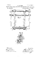
Be it known that I, FRANCIS MEISEL, a citizen of the United States, residing at Boston, in the county of Suffolk and State of Massachusetts, have invented certain Improvements in Machines for Cutting into Strips and Reeling or Winding Paper, Gard-Board, Cloth, and other Similar Materiah'of which the following is a full, clear, and exact description, reference being had to the accompanying drawings, making part of this specification, in which- Figure 1 is a front elevation of my improved machine for cutting into strips and winding paper, card board, &c., a portion of the paper being operated upon, and also a portion of the cutter shafts in front, being broken away to show the parts behind. Fig. 2 isa transverse vertical section through the center of the machine. Fig. 3is a side elevation of the machine. Fig. 4 is an enlarged detail of one of the small cutter shafts and a portion of the larger cutter shaft which co-operates therewith. Fig.5 is a sectional detail of the large cutter shaft, illustrating the manner in which it is supported at its ends. Fig. 6 is a sectional detail on the line as, w of Fig. 1, showing the arrangement of the gears inside the framework at one end of the machine. Fig. 7 is a plan showing the swinging pressure roll frame at the top of the machine. Fig. 8 is a sectional detail on the line y, y of Fig. 1, showing the arrangement of the journal boxes of the small cutter shafts.
My invention relates to an improved machine for cutting into strips paper, card-board, cloth, and other similar material, and reeling or winding it up into rolls, and has for its object to perform these operations in a more perfect and satisfactory manner than heretofore.
To this end my invention consists in certain novel combinations of parts and details of construction as hereinafter set forth and specifically pointed out in the claims.
In the said drawings, A representsthe framework of the machine, outside of which upon a suitable stud formed at the end of a tie-bar 10 is mounted the driving pulley B, upon the hub of which is a pinion O which meshes with and drives the gear Dsecured to the end of a friction feed or winding cylinder E, consisting of a tubular shell or core-shaft 12, over $erial No. 433,921- (No model.)
which are placed a series of thin steel cutting disks a, and rings orcollars b of the same diameter, the collars 6 being chamfered ed at one edge as seen in Figs. land 5, to allow the smallercutting disks 0, Figs. 1 and 4, to cooperate therewith and cut the paper into strips of the desired width.
The cutting disks or are made reversible in order that both edges may be utilized, and the rings or collars b may be of different widths, and may be so arranged in connections with the disks 0 as to cut a series of strips of different widths at the same time. The cylinder E is provided at one end with a supporting shaft 15,the journal of which runs in a box or bearing in one side of the framework, while the opposite end of the cylinder E is supported by and runs upon a sliding center pin e, which enters a conical recess in a plugfdriven into the end of the core-shaft 12, as seen in Fig. 5, said center pin 6 being held in position by a screw g, Fig. 1, provided with a crank handle h and mounted in an arm t provided with a hub or sleeve 7c turning freelyon astud outside the frameworkformed on one end of the tie bar 10, whereby the arm t'with the screw g may be readily swung. to one side to permit the center-pin e to be withdrawn to enable the cutting disks and collars on the cylinder E to be quickly removed and I changed to cut strips of different widths.
At one end of the cylinder E is a shoulder Z, Figs. 4 and 5, and at the opposite end a threaded collar or nut m of the same diameter as the rings and disks, and provided with holes nfor a wrench, whereby said nut may be screwed over one end of the core-shaft 12 tightly up against the last ring of the series to clamp the rings and cutters upon thecyl- 'inder.
On the supporting shaft 15 0f the cylinder E inside the framework, is a gear 1) which meshes with and drives the gears q, r, 8, Figs. 1 and 6, fasten the shafts G, which carry the small circular knives-or cutting disks 0 secured to their shafts by means of screws 25, whereby they may be adjusted longitudinally on said shafts to correspond to the positions of the large cutting disks a of the cylinder E with which they co-operate. The cutter shafts G have their hearings in boxes 20 which are placed, as seen in Figs. 4 and 8, in radial slots a in the sides of the framework A, in suit able recesses at the bottom of which are placed spiral springs b which bear against the boxes 11; and tend to force the same outward against the swinging buttons or latches a which extend thcreover, as seen in Figs. 1, 3, and 8, whereby when the bolts (1' on which the buttons are pivoted are loosened,- or the buttons are removed or swung. to one side, the springs b will force the shafts G outward away from the cylinder E,thereby withdrawing the smaller cutters 0 out of contact with thelarge cutting disks a on said cylinder, as is necessary to permit the end of the roll of paperor other material to pass between thelarger and smaller cutters at the commencement of the operation, or when it is desired to remove or adjust the cutting disks for strips of diiferent widths.
The boxes 20 atthe right hand end of the machine are each provided with a tubular extension 16 containing a spiral spring 18 as seen in Fig. t, and dotted in Fig. 1, which acts against the adjacent end of the shaft G and serves to force it in the proper direction to produce a lateral separation of the cutting disks a and c, which should be effected before the shaft G is forced away by the springs b from the cylinder E. At the opposite or left hand side of the machine the boxes w are each provided with a tubular extension e, to
the outer end of which is fitted, With a check nut 20, a screw f which bears against the adjacent end of the shaft G, whereby when the screw f is turned in by means of its handle 25, the shaft G will be moved longitudinally against the influence of the spring 18, andin this manner the entire series of cutters c on the shaft G may be simultaneously adjusted laterally to bring them into proper working contact with the cutting disks a of the cylinder E, thereby avoiding the delayand incon- Venience of setting up each cutter separately and independently as has hitherto been customary, and insuring a perfect and uniform working contact between the cutting disks as required to produce a clean smooth cut. In the same manner all of the cutters 0 upon a shaft G can be withdrawn or separated laterally from their co-operating cutters a at a single operation bya slight backward movement of the screw f belonging to said shaft,which will permit the spring 18 at the opposite end to force the shaft in the properdirection to effect this movement or adjustment.
\Vhen it is desired to out very narrow strips of paper, the rows of disks 0 may be arranged as shown in Fig. 1, in connection with their counterpart cutters a, so that those of one will sub-divide the strips cut by the row above.
The paper or other material to be cut into strips'and reeled up is taken from a roll I-I, Figs. 2 and 3, mounted on a shaft g having its hearings in the framework of the machine, the paper thence passing under a guide roll it, over a guide roll i, and under and partially around the winding and cutting cylinder E, where it is cut into strips by the circular cutters a and c, said strips being then wound up on a core shaft or mandrel I, and forming a roll K, which rests partially on the cylinder E and partially on another winding drum or cylinder L of the same diameter, and parallel with the cylinder E. The shaft of the cylinder L has secured to it at one end a gear Figs. 3 and 6, which meshes with and is driven by an intermediate gear 1' which is mounted upon a stud projecting from the framework, and meshes with and is driven by the gear 1) at the end of the cylinder E. The face of the gear 1 is double the width of the gear 19 to enable it to engage and drive the gear k which lies in a plane on one side of the gear 19 as seen in the upper portion of Fig. (5. By thus arranging the gears 19, 7a in different planes, I am enabled to bring the surfaces or peripheries of the two winding cylinders E, L, very close together, as is necessary to enable me to use a very small core shaftor mandrel upon which to wind the cut strips.
The two cylinders E, L, revolve in the same direction, but the cylinder L, the surface of which is preferably roughened, revolves with a greater surface velocity than the cylinder E by reason of the gear 7: being of smaller diameter and having a smaller number of teeth than the gear 19, and said cylinders form friction feed or winding cylinders which serve to rotate the roll K by frictional contact therewith, and as the said roll increases in diameter, the ends or journals of the core or mandrel I on which it is wound, rise vertically in guide grooves or ways m, Figs. 2 and 3, in the opposite side of the framework. By thus causing the cylinder L to revolve with a greater surface velocity than the cylinder E, the cut strips are kept stretched over the cylinder E, and tightly wound on the core shaft or roll, one close against the other,without IIO interlapping, whereby the cut rolls can be readily separated and removed from the core shaft.
M is an auxiliary friction winding and pressure roll, which bears upon the top of the roll K and is rotated by mechanism to be presently described with a surface velocity as great or greater than that of the friction winding cylinder L, which, together with its downward pressure, insures the positive rotation of the roll K, particularly when the diameter of the latter is small at the commencement of the operation, and its weight consequently light. The roll M is mounted in a pair of swinging arms 1;, p, the ends of its journals fitting within the vertical grooves or ways m, whereby as the roll M is raised, it is kept directly over the center of the roll- K. The arms p, p, are secured to an oscillating shaft N supported at its opposite ends in hearings in the ends of two swinging arms q, q, secured to a shaft 1", oscillating in bearings s, s, in the framework A; said arms q, g, being provided with adjustable weights t, t,
for varying the pressure of the roll M on the roll of cut strips K, which is thereby pressed against the friction winding cylinders E, L, with sufficient force to insure its being properly rotated to cause the cut strips of paper to be tightly wound into a solid roll. To one end of the roll M is secured a pinion w,Figs. 1 and 3, which meshes with and is driven by a gear a having fastened to one sidea sheave or pulley W, said gear and pulley being mounted on a stud c projecting from the inner side of one of the arms p as seen in Fig. 1.
P is a gear mounted upon a stud projecting from the framework, and meshing with and driven bythe gear is of 'the cylinder L, as shown in Figs. 2, 3, and 6, said gear P carrying a sheave or pulley d from which motion is communicated to the pulley b and gear a,
. by means of a belt Q which runs over two independent pulleys e f Fig. 1, running loosely on a stud 9 Fig. 2, projecting from the end of a bell-crank lever R, fulcrumed at 71 and having pivoted to its shorter arm a rod 2' the lower end of which slides in an eye or guide between which and an adjustable collar 1 it is encircled by a spiral spring m which tends to force the rod 2' upward and thereby keep the belt Q at all times tightly stretched as required, the spring m yielding to the movement of the bell-crank lever B as the pressure roll M and pulley b are raised by the increase in diameter of the roll K as the cut strips are wound or reeled up thereon. At the upper ends of the grooves m are lateral recesses or notches (1 Fig. 2, for the reception of the journals of the pressure roll M v when itis desired tohold the s'amein a raised position out of the way of the roll K.
WhatI claim as my invention, and desire to secure by Letters Patent, is-- 1. In a machine for cutting and winding paper 850., thefeed cylinder E provided with a series of removable cutters, combined with a sliding. center pin adapted to enter a recess in one end of said cylinder to support the same, a screw adapted to hold the center pin in place, said-screw being provided with a handle, and being mounted in a laterally swinging mnt', whereby it may be moved to one-side to permit the center pin to be withdrawn to release the end of the feed cylinder E whenits cutters are to be removed or adjusted, substantially as set forth.
2. In a machine for cuttin and winding paper the, the two friction winding cylinders E, L, revolving in the same directiongandadapted to support the roll of cut material being reeled up, combined with a pressure roll adapted to bear on the said roll of cut material, and mechanism for rotating said pressure roll, substantially as set forth.
3. In a machine for cutting and winding paper 850., the two friction windingcyliuders E, L, revolving in the samedirection, the cylinder L having agreater surface velocity than the cylinder E, and saidcylinders being adapted to support the roll of cut-material being reeled up, combined with a pressure roll adapted to bear on the said roll of cut material, and mechanism for rotating said pressure roll with a greater surface velocity than that of the winding cylinder L, substantially as set forth.
4. In a machine for cutting and winding paper 850., the combination, with the two friction winding cylinders E, L, revolving in the same direction, of the pressure rollM mounted in arms 1), 10', connected with and ferminga portion of a movable frame, the latter provided with weights and mechanism for rotating the pressure roll M, substantially asdescribed.
5. In a machine for cutting and winding paper &c., the combination of the friction winding cylinders E, L, revolving in the same direction, the pressure roll M mounted in a movable weighted frame and provided with a pinion w, the gear a meshin with said pinion and provided with a pulley ,the gearPprovided with a pulley d, the belt Q connecting the pulleys 12*, d and passing overindependent pulleys e f mounted on a lever or arm provided with a spring tightening device for maintaining a constant tension on the belt, Q, all constructed to operatesubstantially in the manner and for thepurpose set forth.
Witness my hand this 19th day of May, A. V
FRANCIS MEISEL. In presence of- P. E. TESCHEMACHER, HARRY W. AIKEN.
Publications (1)
| Publication Number | Publication Date |
|---|---|
| US492964A true US492964A (en) | 1893-03-07 |
Family
ID=2561807
Family Applications (1)
| Application Number | Title | Priority Date | Filing Date |
|---|---|---|---|
| US492964D Expired - Lifetime US492964A (en) | Machine for cutting into strips and reeling or winding paper |
Country Status (1)
| Country | Link |
|---|---|
| US (1) | US492964A (en) |
Cited By (3)
| Publication number | Priority date | Publication date | Assignee | Title |
|---|---|---|---|---|
| US2834558A (en) * | 1955-04-21 | 1958-05-13 | John G Halpin | Portable re-roll, inspection, measuring, and cutting unit for rugs |
| US3086577A (en) * | 1960-03-09 | 1963-04-23 | David C Gimple | Garment bag making equipment |
| US4256269A (en) * | 1978-12-28 | 1981-03-17 | Tex-Del, Inc. | Carpet roll forming apparatus and method |
-
0
- US US492964D patent/US492964A/en not_active Expired - Lifetime
Cited By (3)
| Publication number | Priority date | Publication date | Assignee | Title |
|---|---|---|---|---|
| US2834558A (en) * | 1955-04-21 | 1958-05-13 | John G Halpin | Portable re-roll, inspection, measuring, and cutting unit for rugs |
| US3086577A (en) * | 1960-03-09 | 1963-04-23 | David C Gimple | Garment bag making equipment |
| US4256269A (en) * | 1978-12-28 | 1981-03-17 | Tex-Del, Inc. | Carpet roll forming apparatus and method |
Similar Documents
| Publication | Publication Date | Title |
|---|---|---|
| US492964A (en) | Machine for cutting into strips and reeling or winding paper | |
| US197477A (en) | kneeland | |
| US610329A (en) | meisel | |
| US524501A (en) | Gore-cutting machine | |
| US672899A (en) | Paper-slitting machine. | |
| US577865A (en) | Winding and slitting machine | |
| US654248A (en) | Paper-cutting machine. | |
| US35592A (en) | Improvement in paper-cutting machines | |
| US164289A (en) | Improvement in machines for perforating paper | |
| US416829A (en) | Trimming and slitting machine | |
| US411535A (en) | Dampening and feeding mechanism for printing-machines | |
| US183112A (en) | Improvement in machines for rolling paper | |
| US195824A (en) | Improvement in machines for feeding and cutting paper and other materials | |
| US916562A (en) | Printing-press. | |
| US695029A (en) | Machine for making blanks for paper boxes. | |
| US5671A (en) | Machinery fob | |
| US499424A (en) | Resawing-machine | |
| US404645A (en) | Machine for cutting cloth into strips | |
| US380288A (en) | Paper feeding and cutting device | |
| US186133A (en) | Improvement in machines for cutting paper and other material | |
| US721144A (en) | Paper-bag machine. | |
| US492871A (en) | Perforating and cutting machine | |
| US1125648A (en) | Paper-cutting machine. | |
| US1225131A (en) | Machine for making paper box-blanks. | |
| US444136A (en) | Mechanism |