US4928254A - Laser flash thermal conductivity apparatus and method - Google Patents
Laser flash thermal conductivity apparatus and method Download PDFInfo
- Publication number
- US4928254A US4928254A US07/187,372 US18737288A US4928254A US 4928254 A US4928254 A US 4928254A US 18737288 A US18737288 A US 18737288A US 4928254 A US4928254 A US 4928254A
- Authority
- US
- United States
- Prior art keywords
- sample
- data
- pulses
- temperature rise
- radiant energy
- Prior art date
- Legal status (The legal status is an assumption and is not a legal conclusion. Google has not performed a legal analysis and makes no representation as to the accuracy of the status listed.)
- Expired - Fee Related
Links
Images


Classifications
-
- G—PHYSICS
- G01—MEASURING; TESTING
- G01N—INVESTIGATING OR ANALYSING MATERIALS BY DETERMINING THEIR CHEMICAL OR PHYSICAL PROPERTIES
- G01N21/00—Investigating or analysing materials by the use of optical means, i.e. using sub-millimetre waves, infrared, visible or ultraviolet light
- G01N21/62—Systems in which the material investigated is excited whereby it emits light or causes a change in wavelength of the incident light
- G01N21/71—Systems in which the material investigated is excited whereby it emits light or causes a change in wavelength of the incident light thermally excited
-
- G—PHYSICS
- G01—MEASURING; TESTING
- G01N—INVESTIGATING OR ANALYSING MATERIALS BY DETERMINING THEIR CHEMICAL OR PHYSICAL PROPERTIES
- G01N25/00—Investigating or analyzing materials by the use of thermal means
- G01N25/18—Investigating or analyzing materials by the use of thermal means by investigating thermal conductivity
Definitions
- the present invention relates generally to thermal diffusivity measurement using laser flash techniques. More particularly, the invention relates to an improved laser flash apparatus and method which provides high accuracy at comparatively low laser power levels, so that the sample under test, and any coating applied thereto, are not appreciably degraded or damaged during the test.
- thermal diffusivity is an important factor in designing new substrate materials to conduct heat away from electronic components.
- Ceramic materials are becoming increasingly popular in this application, since these materials can demonstrate comparatively high thermal conductivity with comparatively low electrical conductivity.
- the ability to quickly and accurately measure thermal diffusivity is quite important.
- accurate and conveniently obtainable diffusivity data the ceramic engineer or scientist can more readily experiment with new formulations and fine-tune existing formulations for optimal thermal conductivity.
- the Parker method employs a thermal pulse source in the form of a flash tube (lasers are commonly used today) to apply a thermal pulse to one surface or portion of the sample under test.
- the thermal pulse propagates through the sample, manifesting itself as a temperature variation in the sample over time.
- a temperature sensor such as a thermocouple contact sensor or an infrared noncontact sensor, senses a temperature rise on the rear surface or portion of the sample, which is indicative of the thermal diffusivity of the sample.
- the sensor output is fed to an oscilliscope to which a camera is attached for photographing the oscilliscope waveform.
- the waveform represents the temperature variation as a function of time.
- Diffusivity is then calculated based on the one-half time (t 1/2 ), that is, the time taken for the temperature to rise halfway between the ambient starting temperature and the final temperature, as revealed in the photograph of the oscilloscope waveform.
- t 1/2 the one-half time
- the relationship between one-half time and diffusivity may be expressed by the following equation: ##EQU1## where ⁇ is the diffusivity and L is the sample thickness.
- Thermal conductivity (K) is the product is diffusivity ( ⁇ ), the density ⁇ ) and the heat capacity (C p ):
- Ceramic substrates of the type presently used in the semiconductor industry are comparatively thin (on the order of 25 to 40/1000ths of an inch) and are often not fully opaque at these thicknesses. Optical transmission through these samples is problematic and can adversely affect the sensor and alter or disturb the diffusivity data.
- Providing the ceramic substrate with a coating of opaque material will, of course, prevent optical transmission from interfering with the sensor, although there has been a considerable problem with the laser energy destroying the coating and thereby exposing the sensor to unwanted illumination.
- the present invention overcomes the coating destruction problem by advantageously utilizing a low power laser as a radiant energy heat pulse source.
- the laser employed in the presently preferred embodiment develops an output heat pulse on the order of 0.7 joules, in contrast with the significantly higher powered lasers used in conventional flash methods.
- Parker used a flash tube dissipating 400 joules of energy in each flash.
- a more recent publication described a modified Parker technique using a ruby laser producing 3 joules of energy. See Yutaka Tada et al., "Laser Flash Method for Measuring Thermal Conductivity of Liquids-Application to Low Thermal Conductivity Liquids," Rev. Sci. Instrum., Vol. 49, No. 9, pp. 1305-1313, September 1978.
- the present invention is able to use inexpensive and nondestructive low power laser sources by means of a sophisticated signal processing technique whereby a plurality of temporally spaced low power radiant energy pulses are applied to a first portion (e.g. front surface) of the sample, each pulse causing a temperature rise to propagate through the sample to a second portion (e.g. rear surface).
- the temperature rise associated with each pulse is individually sensed, preferably using a noncontact infrared sensor, and electrically recorded as data in a two-state memory device such as the random access memory of a computer.
- the data is then statistically processed to derive a set of favored values indicative of the temperature of the second portion of the sample as a function of time.
- the statistical processing includes signal averaging of the sensed data.
- approximately 1000 data samples are taken during the relevant time period which is a function of the rise time of the thermal signal (from the onset of the thermal pulse until approximately three to four t 1/2 times thereafter) for each pulse.
- a plurality of single shot pulses are applied to the sample in succession and the data acquired after each pulse is coded and averaged.
- the thermal pulse signal power at a 0.7 joule output is quite low, the received signal at the sensor is greatly enhanced by the statistical processing. This results from the fact that random signals and noise in the measurement system tends to cancel out when averaged over a number of iterations, whereas the signal of interest resulting from the heat pulse propagation tends to add constructively with successive iterations.
- the statistical processing greatly improves the signal-to-noise ratio and allows the acquisition of good thermal data using the low power heat source.
- the statistically processed data representing a set of favored values indicative of the temperature of the second surface or portion as a function of time, is then further processed to determine the diffusivity of the sample.
- a least squares curve-fitting algorithm is applied to the favored values data and the curve fit is optimized to the data by adjusting numerical parameters indicative of the thermal diffusivity.
- the least squares curve fit algorithm is used based on the a priori assumption that the data will fit a curve defined by the following equation representing sensor reading as a function of time with diffusivity being an adjustable parameter:
- the curve-fitting algorithm as well as the statistical processing may be performed by a digital computer with the diffusivity parameter ( ⁇ ) yielding the desired numerical end result.
- FIG. 1 is a schematic block diagram of the presently preferred embodiment of the laser flash apparatus, also useful in understanding the method of the invention
- FIG. 2 is an enlarged cross-sectional view of an exemplary sample undergoing diffusivity measurement in accordance with the invention
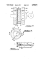
- FIG. 3 is a plan view of a presently preferred sample holder useful in practicing the invention.
- FIG. 4 is a cross-sectional view taken substantially along the line 4--4 of FIG. 3 illustrating the sample holder in greater detail;
- FIG. 5 is a graph of sensor output intensity as a function of time, illustrating the data after statistical processing to yield a set of favored values and also illustrating the curve fit selected by the invention for the illustrated data from which the diffusivity may be determined.
- a yttrium aluminum garnet (YAG) laser 10 delivers a pulsed thermal energy signal to sample 12.
- Laser 10 has an output at a wavelength of 1.06 microns of approximately 0.7 to 1.0 joules per pulse.
- a suitable laser for this purpose is the Quantel Model YG400.
- the presently preferred laser 10 has two modes of operation, a higher power Q-switched mode which delivers approximately 1.0 joules per pulse and a non-Q-switched mode which delivers about 0.7 to 0.85 joules per pulse.
- An optional visible light HeNe laser 14 provides a beam colinear with the invisible YAG laser beam via mirror 17 to aid in sample alignment if desired.
- a photodiode 19 sampling in front of the sample 12 may be used if desired to provide a feedback signal to microcomputer 26 if desired.
- a typical sample 12 may be a thin (less than 2 mm) disk which is opaque to both the YAG laser and to the plasma generated on the surface of the sample, provided with suitable opaque coating if necessary.
- the sample is fixed in a holder such as 1.125 inch inner diameter aluminum cylinder sample holder 16.
- Graphite apertures are placed immediately in front of and behind the sample to prevent any stray laser light and plasma generated light from reaching the detector or sensor 20.
- sample 12 is preferably held in holder 16 by means of three nylon set screws 30.
- the sample 12 is sufficiently thin to permit set screws 30 to act as spacers which prevent the annular graphite masks 32 from touching the sample Masks 32 have circular openings 34 through which the laser beam may illuminate the sample and through which blackbody emission from the sample may reach the detector 20.
- the sample can be provided with a suitable opaque coating to prevent the laser light and plasma generated at the first surface or portion 36 from reaching the sensor 20 positioned to monitor the second surface or portion 38.
- a suitable opaque coating comprises a layer 40 of sputtered gold deposited on first surface or portion 36, followed by a layer of sputtered carbon 42.
- the second surface or portion 38 may also be provided with a coating such as a layer of sputtered carbon 44.
- a 3 inch focal length CaF2 lens 18 collects and focuses the thermal radiation emitted from the second surface of sample 12 onto the input aperture of infrared detector 20.
- Detector 20 can be an InSb photovoltaic detector operating at 77° Kelvin.
- the infrared detector of the presently preferred embodiment has a peak sensitivity at a wavelength of 6 microns.
- the typical sample at room temperature may have a blackbody radiation energy distribution normally centered about a wavelength of approximately 10 microns. As the sample temperature increases in response to the applied thermal pulse, the blackbody radiant energy distribution of the sample shifts towards the shorter wavelengths. As this occurs, the infrared detector receives increasingly more signal at the 6 micron wavelength, thereby giving an indication of increased temperature.
- a HgCdTe infrared detector can also be used.
- the signal from detector 20 is amplified in matched preamplifier 22.
- the output of amplifier 22 is supplied to an analog processor 23 which further amplifies the signal.
- the output of processor 23 is supplied to a transient recorder 24 which includes analog-to-digital converters for digitizing the output signal.
- the transient recorder can be implemented using a Stanford Research Systems Model SR225.
- the sample 12, detector 20, and preferably amplifier 22 can be enclosed in a metal box 26, which functions as a Faraday cage.
- the analog processor is configured to add the signals from the infrared detector and a battery power supply. By adjusting the voltage of the battery power supply the background voltage from the detector is nulled to give essentially a zero reading at the ambient sample temperature prior to subjecting the sample to a thermal pulse.
- the sample can be maintained at ambient room temperature, or the cage can be placed in or configured to serve as a heating or cooling chamber, should it be desired to measure diffusivity at temperatures other than room temperature.
- the transient recorder further includes a digital memory device which collects each digitized scan of thermal data and stores it in a two-state memory device such as random access memory for storing binary data.
- the stored data from transient recorder 24 is transferred to a microcomputer terminal 26 which in turn communicates with a mainframe computer 28.
- the presently preferred embodiment uses a Digital Equipment Corporation LSI/11 microcomputer terminal connected to a VAX 11/785 mainframe computer.
- microcomputer 26 triggers laser 10 causing a first radiant energy pulse to be applied to the first surface or portion 36 of sample 12. If laser 10 is in the Q-switched mode, the pulse is approximately 10 nanoseconds in duration. In the non-Q-switched mode, the pulse is approximately 120 milliseconds in duration. The Q-switched mode thus produces a larger radiant energy peak intensity than the non-Q-switched mode. For samples which require opaque coatings, the lower peak intensity non-Q-switched mode is preferred.
- the front surface temperature can be calculated using the following equation where L is the thickness, T m is the maximum temperature, ⁇ is the diffusivity, y is the pulse width (10 nsec) and ⁇ is a constant equal to approximately 2. (See Parker reference cited above.) ##EQU2##
- the maximum front surface temperature becomes approximately 550° C. for the graphite film (dgf 123).
- other coatings may have different maximum temperature ratings which can be empirically determined or estimated from the above data.
- microcomputer 26 pulses laser 10 on and off preferably at a rate of approximately 4-60 times per minute.
- the time between pulses should be sufficient to allow the thermal pulse to propagate through the sample from front surface or portion 36 to rear surface or portion 38 and to allow the sample to return to ambient temperature.
- the infrared detector collects the thermal response data at the second surface or portion 38 of sample 12 and provides a time varying analog signal to amplifier 22. If desired, the analog signal can be viewed on oscilliscope 50. However, it will be recalled that the laser power is comparatively low, and hence it can be expected that the analog signal will contain a substantial amount of random signal and noise.
- the analog signal is amplified by amplifier 22 and normalized with respect to the ambient temperature by appropriate selection of the battery bias voltage applied to analog processor 23, so that the thermal response of the sample to the applied heat pulse can be measured relative to the ambient temperature baseline.
- the amplified data is digitized in the transient recorder into approximately 1000 data points in a time range from the laser pulse onset until the maximum temperature is reached on the order of three to four t 1/2 times thereafter.
- the data is transferred to microcomputer 26 where the data is stored as individual temperature data points corresponding to each sample time.
- the analog data is sampled 1000 times, then 1000 data points are stored for a given thermal pulse.
- This process is then repeated for the desired number of scans, with the resulting digitized data being coadded to the previously stored data in microcomputer 26 for averaging or otherwise statistically manipulating to minimize the effects of random signals and noise.
- the data collected from each pulse sequence is coadded and averaged sequentially with good results.
- other types of statistical processing could be practiced in place of or in addition to averaging if warranted by the particular nature of the desired signal vis-a-vis noise.
- Preferably greater than 100 scans are taken, with the data for each scan being stored and processed as described above.
- the data in microcomputer 26 is converted from a binary form to an ASCII form for transfer to the mainframe computer 28.
- the mainframe computer operates upon this data using a RS/E least squares curve fitting algorithm in order to fit the data to the analytical expression:
- Suitable software for performing the least squares curve fit algorithm is available for the VAX 11/785 computer from BBN Software Products Corporation.
- the least squares fit algorithm performs a successive number of iterations by adjusting parameters a, b and c of equation (3) until the optimal fit is achieved.
- the diffusivity is then calculated using equation (4) and the result may be output for display on microcomputer terminal 26.
- the display may include the numerically calculated diffusivity value ( ⁇ ) and may also include a graphical display of the data superimposed upon the curve determined by the curve fit algorithm.
- FIG. 5 illustrates an exemplary output curve including the actual data 60 and the superimposed curve fit data 70. As will be seen, the curve fit data matches the actual data quite closely.
- Equation (3) comprises the first two terms of an infinite series: ##EQU3## where T m is the maximum temperature, ⁇ is the diffusivity, n is the index, t is the time, L is the thickness and T is the temperature. If desired, a greater number or fewer number of terms of this series can be used, with the greater number providing greater accuracy and the lesser number providing a lesser accuracy. The number of terms selected for the curve fit computation is inversely related to the computation time required to find a suitable fit. Using only two terms of the series the present invention has demonstrated very good results with a resolution on the order of 1/10th of a degree Centigrade.
Abstract
Description
K=αC.sub.p ρ (2)
f(x)=c+b(1=2exp(-ax)+2exp(-4ax)) (3)
α=a(L/π) (4)
              TABLE I
______________________________________
Energy (mJ) Peak Power (MW)
                          Damage (Y/N)
______________________________________
40          4             N
70          7             Y
90          9             Y
700         70            Y
______________________________________
f(x)=c+b(1=2exp(-ax)+2exp(-4ax)) (3)
α=a(L/π) (4)
Claims (8)
f(x)=c+b(1-2exp(-ax)+2exp(-4ax))
Priority Applications (1)
| Application Number | Priority Date | Filing Date | Title |
|---|---|---|---|
| US07/187,372 US4928254A (en) | 1988-04-28 | 1988-04-28 | Laser flash thermal conductivity apparatus and method |
Applications Claiming Priority (1)
| Application Number | Priority Date | Filing Date | Title |
|---|---|---|---|
| US07/187,372 US4928254A (en) | 1988-04-28 | 1988-04-28 | Laser flash thermal conductivity apparatus and method |
Publications (1)
| Publication Number | Publication Date |
|---|---|
| US4928254A true US4928254A (en) | 1990-05-22 |
Family
ID=22688711
Family Applications (1)
| Application Number | Title | Priority Date | Filing Date |
|---|---|---|---|
| US07/187,372 Expired - Fee Related US4928254A (en) | 1988-04-28 | 1988-04-28 | Laser flash thermal conductivity apparatus and method |
Country Status (1)
| Country | Link |
|---|---|
| US (1) | US4928254A (en) |
Cited By (45)
| Publication number | Priority date | Publication date | Assignee | Title |
|---|---|---|---|---|
| DE4239479A1 (en) * | 1992-11-21 | 1994-05-26 | Hannover Laser Zentrum | Methods for recognizing and sorting different plastics |
| DE4301987A1 (en) * | 1993-01-26 | 1994-07-28 | Soelter Nikolai | Apparatus and method for determining the specific heat capacity by means of a heat pulse and at the same time determining the temperature conductivity |
| US5374122A (en) * | 1993-01-29 | 1994-12-20 | The United States Of America As Represented By The Secretary Of The Air Force | Method for quantifying porosity of parts of simple and complex geometries |
| US5439291A (en) * | 1992-03-02 | 1995-08-08 | Ta Instruments, Inc. | Method and apparatus for AC Differential thermal analysis |
| US5474385A (en) * | 1992-03-02 | 1995-12-12 | Ta Instruments, Inc. | Method and apparatus for parsed dynamic differential analysis |
| US5549387A (en) * | 1994-06-01 | 1996-08-27 | The Perkin-Elmer Corporation | Apparatus and method for differential analysis using real and imaginary signal components |
| US5558790A (en) * | 1994-02-15 | 1996-09-24 | Science Applications International Corporation | Method and laser system for the thermal analysis of a substance |
| US5562345A (en) * | 1992-05-05 | 1996-10-08 | The United States Of America As Represented By The Administrator Of The National Aeronautics And Space Administration | Method and apparatus for thermographically and quantitatively analyzing a structure for disbonds and/or inclusions |
| US5624187A (en) * | 1992-03-02 | 1997-04-29 | Ta Instruments, Inc. | Method and apparatus for gas flow modulated differential scanning calorimetry |
| GB2311851A (en) * | 1996-04-03 | 1997-10-08 | Aea Technology Plc | Wigner energy measurement |
| US5713665A (en) * | 1995-05-12 | 1998-02-03 | Agency Of Industrial Science & Technology, Ministry Of International Trade & Industry | Method and apparatus for thermal diffusivity measurement |
| US5801968A (en) * | 1996-04-23 | 1998-09-01 | Deltatrak, Inc. | Parameter end point measuring device |
| US5823677A (en) * | 1996-03-18 | 1998-10-20 | The Board Of Trustees Of Western Michigan | Method of identifying a substance by infrared imaging |
| WO2000016079A1 (en) * | 1998-09-14 | 2000-03-23 | Forschungszentrum Karlsruhe Gmbh | Method for determining the quality of adhesion in a laminar structure |
| US6331075B1 (en) | 1998-05-01 | 2001-12-18 | Administrator, National Aeronautics And Space Administration | Device and method for measuring thermal conductivity of thin films |
| NL1015691C2 (en) * | 2000-07-12 | 2002-01-15 | Tno | System for detecting deposition on a surface. |
| US6375349B1 (en) | 1999-08-05 | 2002-04-23 | Anter Corporation | Instrument configured to test multiple samples for the determination of thermophysical properties by the flash method |
| US20020197731A1 (en) * | 1996-10-09 | 2002-12-26 | Symyx Technologies, Inc. | Infrared spectroscopy imaging of libraries |
| WO2003002998A2 (en) * | 2001-06-27 | 2003-01-09 | Mathis Instruments Ltd. | Method and apparatus for monitoring substances |
| US6517238B2 (en) * | 2001-01-18 | 2003-02-11 | The United States Of America As Represented By The United States Department Of Energy | Thermal imaging measurement of lateral diffusivity and non-invasive material defect detection |
| US6592252B2 (en) * | 2000-10-17 | 2003-07-15 | National Institute Of Advanced Industrial Science And Technology | Method for measuring thermal diffusivity and interface thermal resistance |
| US6595685B2 (en) * | 1998-10-13 | 2003-07-22 | National Research Laboratory Of Metrology | Method and apparatus for measuring thermophysical properties |
| US6712502B2 (en) * | 2002-04-10 | 2004-03-30 | The United States Of America As Represented By The Administrator Of The National Aeronautics And Space Administration | Synchronized electronic shutter system and method for thermal nondestructive evaluation |
| DE10242741A1 (en) * | 2002-09-13 | 2004-04-01 | Netzsch-Gerätebau GmbH | Device for determining thermal conductivity using light pulses has reference radiation sensor with bandwidth significantly greater than reciprocal of radiation source pulse length for correcting infrared sensor signals |
| US20040241752A1 (en) * | 1998-02-03 | 2004-12-02 | Anderson Emory V. | Point of care diagnostic systems |
| EP1491881A1 (en) * | 2003-06-23 | 2004-12-29 | Ludovit Kubicar | Method and device for measuring thermophysical parameters of materials by pulse transient method |
| US20050099835A1 (en) * | 2003-11-04 | 2005-05-12 | Electro Scientific Industries, Inc. | Laser-based termination of passive electronic components |
| US20060127599A1 (en) * | 2002-02-12 | 2006-06-15 | Wojak Gregory J | Process and apparatus for preparing a diamond substance |
| US20060153269A1 (en) * | 2002-11-20 | 2006-07-13 | Fereydoun Lakestani | Method and system for measuring the thermal diffusivity |
| US20060216955A1 (en) * | 2003-11-04 | 2006-09-28 | Swenson Edward J | Laser-based termination of miniature passive electronic components |
| FR2894335A1 (en) * | 2005-12-06 | 2007-06-08 | Commissariat Energie Atomique | Object e.g. insulator, thermal conductivity measuring method for e.g. building, involves increasing temperature of one side of object e.g. insulator, for specific duration, and measuring temperature of another side of object |
| US20070143061A1 (en) * | 2005-12-16 | 2007-06-21 | Ringermacher Harry I | Method and apparatus for nondestructive evaluation of insulative coating |
| US20080317090A1 (en) * | 2007-06-20 | 2008-12-25 | General Electric Company | Method and apparatus for thermographic nondestructive evaluation of an object |
| US20090110025A1 (en) * | 2007-10-26 | 2009-04-30 | Korea Advanced Institute Of Science And Technology | Apparatus and method for measuring thermal diffusivity using the flash method |
| CN101782542A (en) * | 2010-03-02 | 2010-07-21 | 长安大学 | System and method for testing moisture and temperature of soil mass by heat pulse method |
| CN102226775A (en) * | 2011-03-16 | 2011-10-26 | 中国科学院上海技术物理研究所 | Method and apparatus for measuring material thermal conductivity based on optical-modulated thermo-emission spectroscopy |
| CN104040327A (en) * | 2011-12-23 | 2014-09-10 | 西格里碳素欧洲公司 | Method for measuring thermal conductivity |
| CN106053530A (en) * | 2016-08-09 | 2016-10-26 | 武汉钢铁股份有限公司 | Calculation method of thermal conductivity coefficient of refractory material |
| EP3372340A1 (en) | 2017-03-10 | 2018-09-12 | Scheppach Fabrikation von Holzbearbeitungsmaschinen GmbH | Method for controlling an electric tool and electric tool set up for carrying out the method |
| WO2020151780A1 (en) | 2019-01-24 | 2020-07-30 | Friedrich-Schiller-Universität Jena | Device and method for simultaneously determining temperature-dependent thermal conductivity, thermal diffusivity and specific heat capacity |
| US10809213B2 (en) | 2017-11-30 | 2020-10-20 | Battelle Energy Alliance, Llc | Sensors for measuring thermal conductivity and related methods |
| RU213568U1 (en) * | 2022-03-23 | 2022-09-16 | Российская Федерация, от имени которой выступает Государственная корпорация по атомной энергии "Росатом" (Госкорпорация "Росатом") | DEVICE FOR DETERMINING THE ENERGY DENSITY IN A DEVICE FOR DETERMINING THERMAL CONDUCTIVITY BY THE LASER FLASH METHOD |
| EP4170323A1 (en) * | 2021-10-22 | 2023-04-26 | Linseis Messgeräte GmbH | Thermal diffusivity measuring apparatus |
| US11719656B2 (en) | 2020-10-02 | 2023-08-08 | Ut-Battelle, Llc | Variable gap thermal conductivity apparatus and method |
| US11796496B1 (en) | 2022-08-29 | 2023-10-24 | Arrigo Enterprises, Llc | Instrument and method for measuring thermal diffusivity of materials |
Citations (4)
| Publication number | Priority date | Publication date | Assignee | Title |
|---|---|---|---|---|
| US4232543A (en) * | 1979-02-28 | 1980-11-11 | The President Of Kyoto University | Device for measuring thermal conductivity of liquids |
| US4283935A (en) * | 1979-03-19 | 1981-08-18 | President Of Kyoto University | Device for measuring thermal conductivity of liquid |
| US4568198A (en) * | 1982-06-03 | 1986-02-04 | Budapesti Muszaki Egyetem | Method and apparatus for the determination of the heat transfer coefficient |
| US4630938A (en) * | 1983-04-27 | 1986-12-23 | Polska Akademia Nauk Centrum Badan Molekularnych I Makromolekularnych | Method of determination of thermal conduction coefficient and heat capacity of materials and the apparatus for measurements of thermal conduction coefficient and heat capacity of material |
-
1988
- 1988-04-28 US US07/187,372 patent/US4928254A/en not_active Expired - Fee Related
Patent Citations (4)
| Publication number | Priority date | Publication date | Assignee | Title |
|---|---|---|---|---|
| US4232543A (en) * | 1979-02-28 | 1980-11-11 | The President Of Kyoto University | Device for measuring thermal conductivity of liquids |
| US4283935A (en) * | 1979-03-19 | 1981-08-18 | President Of Kyoto University | Device for measuring thermal conductivity of liquid |
| US4568198A (en) * | 1982-06-03 | 1986-02-04 | Budapesti Muszaki Egyetem | Method and apparatus for the determination of the heat transfer coefficient |
| US4630938A (en) * | 1983-04-27 | 1986-12-23 | Polska Akademia Nauk Centrum Badan Molekularnych I Makromolekularnych | Method of determination of thermal conduction coefficient and heat capacity of materials and the apparatus for measurements of thermal conduction coefficient and heat capacity of material |
Non-Patent Citations (29)
| Title |
|---|
| A. Chmielewski et al., "Computerized Data Acquisition and Analysis For Measuring Thermal Diffusivity" Society of Automotive Engineers, Inc. No. 859462 1985, pp. 3.565-3.568. |
| A. Chmielewski et al., Computerized Data Acquisition and Analysis For Measuring Thermal Diffusivity Society of Automotive Engineers, Inc. No. 859462 1985, pp. 3.565 3.568. * |
| Andrew Whittaker et al., "Thermal Diffusivity of Some Fine-Weave Carbon/Carbon-Fibre Composites," High Temperatures--High Pressures, vol. 17, 1985, pp. 225-231. |
| Andrew Whittaker et al., Thermal Diffusivity of Some Fine Weave Carbon/Carbon Fibre Composites, High Temperatures High Pressures, vol. 17, 1985, pp. 225 231. * |
| D. L. Balageas, "Nouvelle Methode D'interpretation des Thermogrammes Pour la Determination de la Diffusivite Thermique par la Methode Impulsionnelle," Revue Phys. Appl., vol. 17, Apr. 1982, pp. 227-237. |
| D. L. Balageas, Nouvelle Methode D interpretation des Thermogrammes Pour la Determination de la Diffusivite Thermique par la Methode Impulsionnelle, Revue Phys. Appl., vol. 17, Apr. 1982, pp. 227 237. * |
| F. Righini et al., "Pulse Method of Thermal Diffusivity Measurements (A Review)," High Temperatures--High Pressures, vol. 5, 1973, pp. 481-501. |
| F. Righini et al., Pulse Method of Thermal Diffusivity Measurements (A Review), High Temperatures High Pressures, vol. 5, 1973, pp. 481 501. * |
| Fyzikolny Casopis (1970), No. 1; "Measurement of Thermal Conductivity of Thin Samples of a Finite Length"; J. Kristofic et al., pp. 48-55. |
| Fyzikolny Casopis (1970), No. 1; Measurement of Thermal Conductivity of Thin Samples of a Finite Length ; J. Kristofic et al., pp. 48 55. * |
| H. L. Lee et al., "Comparison of Data For Thermal Diffusivity Obtained by Laser-Flash Method Using Thermocouple and Photodetector," J. Am. Ceram. Soc., vol. 68, No. 1, C-12-C-13, Jan. 1985. |
| H. L. Lee et al., Comparison of Data For Thermal Diffusivity Obtained by Laser Flash Method Using Thermocouple and Photodetector, J. Am. Ceram. Soc., vol. 68, No. 1, C 12 C 13, Jan. 1985. * |
| L. M. Clark III and R. E. Taylor, Journal of Applied Physics, vol. 46, No. 2, 2/1975, pp. 714 719. * |
| L. M. Clark III and R. E. Taylor, Journal of Applied Physics, vol. 46, No. 2, 2/1975, pp. 714-719. |
| L. Pawlowski et al., "The Least Square Method in the Determination of Thermal Diffusivity Using a Flash Method," Revue De Physique Appliquee, vol. 21, No. 2, Feb. 1986, pp. 83-86. |
| L. Pawlowski et al., The Least Square Method in the Determination of Thermal Diffusivity Using a Flash Method, Revue De Physique Appliquee, vol. 21, No. 2, Feb. 1986, pp. 83 86. * |
| M. A. Bucknam et al., "The Measurement of the Thermal Conductivity of Refractories By The Laser-Flash Method," Transactions of the British Ceramic Society, vol. 82, No. 1, 1983, pp. 18-23. |
| M. A. Bucknam et al., The Measurement of the Thermal Conductivity of Refractories By The Laser Flash Method, Transactions of the British Ceramic Society, vol. 82, No. 1, 1983, pp. 18 23. * |
| Martin I. Darby, "Analysis of Thermal Conductivity Experiments on Glass at High Temperatures," High Temperatures--High Pressures, vol. 15, 1983, pp. 629-644. |
| Martin I. Darby, Analysis of Thermal Conductivity Experiments on Glass at High Temperatures, High Temperatures High Pressures, vol. 15, 1983, pp. 629 644. * |
| R. E. Taylor et al., "Thermal Diffusivity of Fiber-Reinforced Composites Using The Laser Flash Techinque," Carbon, vol. 23, No. 2, 1985, pp. 215-222. |
| R. E. Taylor et al., Thermal Diffusivity of Fiber Reinforced Composites Using The Laser Flash Techinque, Carbon, vol. 23, No. 2, 1985, pp. 215 222. * |
| Standard Test Method For Thermal Diffusivity of Carbon and Graphite by a Thermal Pulse Method The American Society for Testing and Materials Designation C714, Aug. 1972. * |
| W. J. Parker et al., "Flash Method of Determining Thermal Diffusivity, Heat Capacity, and Thermal Conductivity*," Journal of Applied Physics, vol. 32, No. 9, Sep. 1961, pp. 1679-1684. |
| W. J. Parker et al., Flash Method of Determining Thermal Diffusivity, Heat Capacity, and Thermal Conductivity*, Journal of Applied Physics, vol. 32, No. 9, Sep. 1961, pp. 1679 1684. * |
| Y. Takahashi, "Measurement of Thermophysical Properties of Metals and Ceramics By the Laser-Flash Method," International Journal of Thermophysics, vol. 5, No. 1, Feb. 8, 1984, pp. 41-52. |
| Y. Takahashi, Measurement of Thermophysical Properties of Metals and Ceramics By the Laser Flash Method, International Journal of Thermophysics, vol. 5, No. 1, Feb. 8, 1984, pp. 41 52. * |
| Yutaka Tada et al., "Laser Flash Method For Measuring Thermal Conductivity Of Liquids--Application To Low Thermal Conductivity Liquids," Rev. Sci. Instrum. vol. 29, No. 9, Sep. 1978, pp. 1305-1314. |
| Yutaka Tada et al., Laser Flash Method For Measuring Thermal Conductivity Of Liquids Application To Low Thermal Conductivity Liquids, Rev. Sci. Instrum. vol. 29, No. 9, Sep. 1978, pp. 1305 1314. * |
Cited By (78)
| Publication number | Priority date | Publication date | Assignee | Title |
|---|---|---|---|---|
| US5624187A (en) * | 1992-03-02 | 1997-04-29 | Ta Instruments, Inc. | Method and apparatus for gas flow modulated differential scanning calorimetry |
| US5439291A (en) * | 1992-03-02 | 1995-08-08 | Ta Instruments, Inc. | Method and apparatus for AC Differential thermal analysis |
| US5474385A (en) * | 1992-03-02 | 1995-12-12 | Ta Instruments, Inc. | Method and apparatus for parsed dynamic differential analysis |
| US5562345A (en) * | 1992-05-05 | 1996-10-08 | The United States Of America As Represented By The Administrator Of The National Aeronautics And Space Administration | Method and apparatus for thermographically and quantitatively analyzing a structure for disbonds and/or inclusions |
| US5489778A (en) * | 1992-11-21 | 1996-02-06 | Laser Zentrum Hannover E.V. | Process and installation for the identification of materials |
| EP0599153A1 (en) * | 1992-11-21 | 1994-06-01 | LASER ZENTRUM HANNOVER e.V. | Method and device for the identification of materials |
| DE4239479A1 (en) * | 1992-11-21 | 1994-05-26 | Hannover Laser Zentrum | Methods for recognizing and sorting different plastics |
| EP0612999A2 (en) * | 1993-01-25 | 1994-08-31 | Sölter, Nicolai | Thermal pulse method and apparatus for determining specific heat capacities and thermal conductivities |
| EP0612999A3 (en) * | 1993-01-26 | 1996-07-03 | Soelter Nicolai | Thermal pulse method and apparatus for determining specific heat capacities and thermal conductivities. |
| DE4301987A1 (en) * | 1993-01-26 | 1994-07-28 | Soelter Nikolai | Apparatus and method for determining the specific heat capacity by means of a heat pulse and at the same time determining the temperature conductivity |
| US5374122A (en) * | 1993-01-29 | 1994-12-20 | The United States Of America As Represented By The Secretary Of The Air Force | Method for quantifying porosity of parts of simple and complex geometries |
| US5558790A (en) * | 1994-02-15 | 1996-09-24 | Science Applications International Corporation | Method and laser system for the thermal analysis of a substance |
| US5549387A (en) * | 1994-06-01 | 1996-08-27 | The Perkin-Elmer Corporation | Apparatus and method for differential analysis using real and imaginary signal components |
| US5713665A (en) * | 1995-05-12 | 1998-02-03 | Agency Of Industrial Science & Technology, Ministry Of International Trade & Industry | Method and apparatus for thermal diffusivity measurement |
| US5823677A (en) * | 1996-03-18 | 1998-10-20 | The Board Of Trustees Of Western Michigan | Method of identifying a substance by infrared imaging |
| GB2311851A (en) * | 1996-04-03 | 1997-10-08 | Aea Technology Plc | Wigner energy measurement |
| GB2311851B (en) * | 1996-04-03 | 1999-09-08 | Aea Technology Plc | Wigner energy measurement |
| US5801968A (en) * | 1996-04-23 | 1998-09-01 | Deltatrak, Inc. | Parameter end point measuring device |
| US20090002708A1 (en) * | 1996-10-09 | 2009-01-01 | Symyx Technologies, Inc. | Methods and apparatus for spectroscopic imaging of materials in an array |
| US7551285B2 (en) | 1996-10-09 | 2009-06-23 | Symyx Technologies, Inc. | Methods and apparatus for spectroscopic imaging of materials in an array |
| US20090045341A1 (en) * | 1996-10-09 | 2009-02-19 | Symyx Technologies, Inc. | Systems for observing reactions using infrared imaging |
| US20020197731A1 (en) * | 1996-10-09 | 2002-12-26 | Symyx Technologies, Inc. | Infrared spectroscopy imaging of libraries |
| US7364697B2 (en) | 1996-10-09 | 2008-04-29 | Symyx Technologies, Inc. | System for infrared spectroscopic imaging of libraries |
| US6541271B1 (en) * | 1996-10-09 | 2003-04-01 | Symyx Technologies, Inc. | Infrared spectroscopic imaging of libraries |
| US20050164304A1 (en) * | 1996-10-09 | 2005-07-28 | Symyx Technologies, Inc. | Infrared spectroscopic imaging of libraries |
| US6849460B2 (en) | 1996-10-09 | 2005-02-01 | Symyx Technologies, Inc. | Infrared spectroscopy imaging of libraries |
| US20040241752A1 (en) * | 1998-02-03 | 2004-12-02 | Anderson Emory V. | Point of care diagnostic systems |
| US7270970B2 (en) * | 1998-02-03 | 2007-09-18 | Adeza Biomedical Corporation | Point of care diagnostic systems |
| US20060008923A1 (en) * | 1998-02-03 | 2006-01-12 | Anderson Emory V | Point of care diagnostic systems |
| US6331075B1 (en) | 1998-05-01 | 2001-12-18 | Administrator, National Aeronautics And Space Administration | Device and method for measuring thermal conductivity of thin films |
| WO2000016079A1 (en) * | 1998-09-14 | 2000-03-23 | Forschungszentrum Karlsruhe Gmbh | Method for determining the quality of adhesion in a laminar structure |
| US6595685B2 (en) * | 1998-10-13 | 2003-07-22 | National Research Laboratory Of Metrology | Method and apparatus for measuring thermophysical properties |
| US6375349B1 (en) | 1999-08-05 | 2002-04-23 | Anter Corporation | Instrument configured to test multiple samples for the determination of thermophysical properties by the flash method |
| NL1015691C2 (en) * | 2000-07-12 | 2002-01-15 | Tno | System for detecting deposition on a surface. |
| WO2002004290A1 (en) * | 2000-07-12 | 2002-01-17 | Nederlandse Organisatie Voor Toegepast-Natuurwetenschappelijk Onderzoek Tno | System for detecting a deposit on a surface |
| US6592252B2 (en) * | 2000-10-17 | 2003-07-15 | National Institute Of Advanced Industrial Science And Technology | Method for measuring thermal diffusivity and interface thermal resistance |
| US6517238B2 (en) * | 2001-01-18 | 2003-02-11 | The United States Of America As Represented By The United States Department Of Energy | Thermal imaging measurement of lateral diffusivity and non-invasive material defect detection |
| WO2003002998A3 (en) * | 2001-06-27 | 2003-08-28 | Mathis Instr Ltd | Method and apparatus for monitoring substances |
| US7048436B2 (en) | 2001-06-27 | 2006-05-23 | Mathis Instruments Ltd. | Method and apparatus for monitoring substances |
| WO2003002998A2 (en) * | 2001-06-27 | 2003-01-09 | Mathis Instruments Ltd. | Method and apparatus for monitoring substances |
| US20050202571A1 (en) * | 2001-06-27 | 2005-09-15 | Mathis Instruments, Ltd. | Method and apparatus for monitoring substances |
| US20040165645A1 (en) * | 2001-06-27 | 2004-08-26 | Nancy Mathis | Method and apparatus for monitoring substances |
| US20060127599A1 (en) * | 2002-02-12 | 2006-06-15 | Wojak Gregory J | Process and apparatus for preparing a diamond substance |
| US6712502B2 (en) * | 2002-04-10 | 2004-03-30 | The United States Of America As Represented By The Administrator Of The National Aeronautics And Space Administration | Synchronized electronic shutter system and method for thermal nondestructive evaluation |
| US7038209B2 (en) * | 2002-09-13 | 2006-05-02 | Netzsch-Geraetebau Gmbh | Device for detecting thermal conductivity by means of optical pulses |
| DE10242741A1 (en) * | 2002-09-13 | 2004-04-01 | Netzsch-Gerätebau GmbH | Device for determining thermal conductivity using light pulses has reference radiation sensor with bandwidth significantly greater than reciprocal of radiation source pulse length for correcting infrared sensor signals |
| DE10242741B4 (en) * | 2002-09-13 | 2005-08-11 | Netzsch-Gerätebau GmbH | Device for determining the thermal conductivity by means of light pulses |
| US20040079886A1 (en) * | 2002-09-13 | 2004-04-29 | Johannes Opfermann | Device for detecting thermal conductivity by means of optical pulses |
| US7364354B2 (en) * | 2002-11-20 | 2008-04-29 | The European Community | Method and system for measuring the thermal diffusivity |
| US20060153269A1 (en) * | 2002-11-20 | 2006-07-13 | Fereydoun Lakestani | Method and system for measuring the thermal diffusivity |
| EP1491881A1 (en) * | 2003-06-23 | 2004-12-29 | Ludovit Kubicar | Method and device for measuring thermophysical parameters of materials by pulse transient method |
| US7378337B2 (en) | 2003-11-04 | 2008-05-27 | Electro Scientific Industries, Inc. | Laser-based termination of miniature passive electronic components |
| US20060216955A1 (en) * | 2003-11-04 | 2006-09-28 | Swenson Edward J | Laser-based termination of miniature passive electronic components |
| US7053011B2 (en) * | 2003-11-04 | 2006-05-30 | Electro Scientific Industries, Inc. | Laser-based termination of passive electronic components |
| US20050099835A1 (en) * | 2003-11-04 | 2005-05-12 | Electro Scientific Industries, Inc. | Laser-based termination of passive electronic components |
| FR2894335A1 (en) * | 2005-12-06 | 2007-06-08 | Commissariat Energie Atomique | Object e.g. insulator, thermal conductivity measuring method for e.g. building, involves increasing temperature of one side of object e.g. insulator, for specific duration, and measuring temperature of another side of object |
| US7409313B2 (en) * | 2005-12-16 | 2008-08-05 | General Electric Company | Method and apparatus for nondestructive evaluation of insulative coating |
| US20070143061A1 (en) * | 2005-12-16 | 2007-06-21 | Ringermacher Harry I | Method and apparatus for nondestructive evaluation of insulative coating |
| US20080317090A1 (en) * | 2007-06-20 | 2008-12-25 | General Electric Company | Method and apparatus for thermographic nondestructive evaluation of an object |
| US7549789B2 (en) * | 2007-06-20 | 2009-06-23 | General Electric Company | Method and apparatus for thermographic nondestructive evaluation of an object |
| US7976215B2 (en) * | 2007-10-26 | 2011-07-12 | Korea Advanced Institute Of Science And Technology | Apparatus and method for measuring thermal diffusivity using the flash method |
| US20090110025A1 (en) * | 2007-10-26 | 2009-04-30 | Korea Advanced Institute Of Science And Technology | Apparatus and method for measuring thermal diffusivity using the flash method |
| CN101782542B (en) * | 2010-03-02 | 2012-10-03 | 长安大学 | System and method for testing moisture and temperature of soil mass by heat pulse method |
| CN101782542A (en) * | 2010-03-02 | 2010-07-21 | 长安大学 | System and method for testing moisture and temperature of soil mass by heat pulse method |
| CN102226775A (en) * | 2011-03-16 | 2011-10-26 | 中国科学院上海技术物理研究所 | Method and apparatus for measuring material thermal conductivity based on optical-modulated thermo-emission spectroscopy |
| CN104040327A (en) * | 2011-12-23 | 2014-09-10 | 西格里碳素欧洲公司 | Method for measuring thermal conductivity |
| CN106053530B (en) * | 2016-08-09 | 2018-11-30 | 武汉钢铁有限公司 | The calculation method of Refractory Thermal Conductivity |
| CN106053530A (en) * | 2016-08-09 | 2016-10-26 | 武汉钢铁股份有限公司 | Calculation method of thermal conductivity coefficient of refractory material |
| EP3372340A1 (en) | 2017-03-10 | 2018-09-12 | Scheppach Fabrikation von Holzbearbeitungsmaschinen GmbH | Method for controlling an electric tool and electric tool set up for carrying out the method |
| WO2018162020A1 (en) | 2017-03-10 | 2018-09-13 | Scheppach Fabrikation Von Holzbearbeitungsmaschinen Gmbh | Method for controlling an electric tool, and electric tool designed for carrying out the method |
| US11256227B2 (en) | 2017-03-10 | 2022-02-22 | Scheppach Fabrikation Von Holzbearbeitungsmaschinen Gmbh | Method for controlling a power tool and power tool configured for carrying out the method |
| US10809213B2 (en) | 2017-11-30 | 2020-10-20 | Battelle Energy Alliance, Llc | Sensors for measuring thermal conductivity and related methods |
| WO2020151780A1 (en) | 2019-01-24 | 2020-07-30 | Friedrich-Schiller-Universität Jena | Device and method for simultaneously determining temperature-dependent thermal conductivity, thermal diffusivity and specific heat capacity |
| DE102019000590A1 (en) | 2019-01-24 | 2020-07-30 | Friedrich-Schiller-Universität Jena | Device and method for the simultaneous determination of the temperature-dependent thermal conductivity, thermal diffusivity and specific heat capacity |
| US11719656B2 (en) | 2020-10-02 | 2023-08-08 | Ut-Battelle, Llc | Variable gap thermal conductivity apparatus and method |
| EP4170323A1 (en) * | 2021-10-22 | 2023-04-26 | Linseis Messgeräte GmbH | Thermal diffusivity measuring apparatus |
| RU213568U1 (en) * | 2022-03-23 | 2022-09-16 | Российская Федерация, от имени которой выступает Государственная корпорация по атомной энергии "Росатом" (Госкорпорация "Росатом") | DEVICE FOR DETERMINING THE ENERGY DENSITY IN A DEVICE FOR DETERMINING THERMAL CONDUCTIVITY BY THE LASER FLASH METHOD |
| US11796496B1 (en) | 2022-08-29 | 2023-10-24 | Arrigo Enterprises, Llc | Instrument and method for measuring thermal diffusivity of materials |
Similar Documents
| Publication | Publication Date | Title |
|---|---|---|
| US4928254A (en) | Laser flash thermal conductivity apparatus and method | |
| US6081330A (en) | Method and device for measuring the thickness of opaque and transparent films | |
| US4243327A (en) | Double-beam optical method and apparatus for measuring thermal diffusivity and other molecular dynamic processes in utilizing the transient thermal lens effect | |
| US5305416A (en) | Semiconductor processing technique, including pyrometric measurement of radiantly heated bodies | |
| DE69730371T2 (en) | Self-calibrating temperature probe | |
| KR970705742A (en) | AUTOMATIC GAIN CONTROL FOR INFRARED RADIATION PYROMETER | |
| US7937240B2 (en) | Method and device for characterizing, using active pyrometry, a thin-layer material arranged on a substrate | |
| Varpula et al. | Optical power calibrator based on a stabilized green He-Ne laser and a cryogenic absolute radiometer | |
| Karner et al. | Pulsed laser photothermal displacement spectroscopy for surface studies | |
| Akoshima et al. | Thermal diffusivity measurements of candidate reference materials by the laser flash method | |
| Chen et al. | Noncontact nanosecond-time-resolution temperature measurement in excimer laser heating of Ni–P disk substrates | |
| Nettesheim et al. | Pulsed laser heating of surfaces: nanosecond timescale temperature measurement using black body radiation | |
| Xu et al. | Measurement of solid–liquid interface temperature during pulsed excimer laser melting of polycrystalline silicon films | |
| EP0192722B1 (en) | Apparatus and method for static stress measurement in an object | |
| JPS6250652A (en) | Method and instrument for measuring thermal diffusivity | |
| US4755049A (en) | Method and apparatus for measuring the ion implant dosage in a semiconductor crystal | |
| US6375349B1 (en) | Instrument configured to test multiple samples for the determination of thermophysical properties by the flash method | |
| Cuneo et al. | A refractive index gradient (RING) diagnostic for transient discharges or expansions of vapor or plasmas | |
| Grilli et al. | Thermal conductivity of e-beam coatings | |
| Mann | Automated damage testing facility for excimer laser optics | |
| Li et al. | Nonlinearity measurements of high-power laser detectors at NIST | |
| Dai et al. | Development of a millisecond pulse-heating apparatus | |
| Skolnik | A review of techniques for measuring small optical losses in infrared transmitting materials | |
| Moksin et al. | Thermal diffusivity measurement of black and metallic graphite paint coatings | |
| Polland et al. | A difference detection system for high precision measurements of ultrafast transmission changes |
Legal Events
| Date | Code | Title | Description |
|---|---|---|---|
| AS | Assignment |
Owner name: DOW CHEMICAL COMPANY, THE, MICHIGAN Free format text: ASSIGNMENT OF ASSIGNORS INTEREST.;ASSIGNORS:KNUDSEN, ARNE K.;DELZER, SCOTT H.;LANGHOFF, CHARLES A.;REEL/FRAME:005252/0701 Effective date: 19880622 |
|
| FEPP | Fee payment procedure |
Free format text: PAYOR NUMBER ASSIGNED (ORIGINAL EVENT CODE: ASPN); ENTITY STATUS OF PATENT OWNER: LARGE ENTITY |
|
| FPAY | Fee payment |
Year of fee payment: 4 |
|
| REMI | Maintenance fee reminder mailed | ||
| LAPS | Lapse for failure to pay maintenance fees | ||
| FP | Lapsed due to failure to pay maintenance fee |
Effective date: 19980527 |
|
| STCH | Information on status: patent discontinuation |
Free format text: PATENT EXPIRED DUE TO NONPAYMENT OF MAINTENANCE FEES UNDER 37 CFR 1.362 |