US4925002A - Conveyorized sortation system - Google Patents
Conveyorized sortation system Download PDFInfo
- Publication number
- US4925002A US4925002A US07/367,871 US36787189A US4925002A US 4925002 A US4925002 A US 4925002A US 36787189 A US36787189 A US 36787189A US 4925002 A US4925002 A US 4925002A
- Authority
- US
- United States
- Prior art keywords
- conveyor
- packages
- divider
- transition section
- distribution
- Prior art date
- Legal status (The legal status is an assumption and is not a legal conclusion. Google has not performed a legal analysis and makes no representation as to the accuracy of the status listed.)
- Expired - Lifetime
Links
Images


Classifications
-
- B—PERFORMING OPERATIONS; TRANSPORTING
- B07—SEPARATING SOLIDS FROM SOLIDS; SORTING
- B07C—POSTAL SORTING; SORTING INDIVIDUAL ARTICLES, OR BULK MATERIAL FIT TO BE SORTED PIECE-MEAL, e.g. BY PICKING
- B07C5/00—Sorting according to a characteristic or feature of the articles or material being sorted, e.g. by control effected by devices which detect or measure such characteristic or feature; Sorting by manually actuated devices, e.g. switches
- B07C5/36—Sorting apparatus characterised by the means used for distribution
-
- B—PERFORMING OPERATIONS; TRANSPORTING
- B07—SEPARATING SOLIDS FROM SOLIDS; SORTING
- B07C—POSTAL SORTING; SORTING INDIVIDUAL ARTICLES, OR BULK MATERIAL FIT TO BE SORTED PIECE-MEAL, e.g. BY PICKING
- B07C3/00—Sorting according to destination
- B07C3/02—Apparatus characterised by the means used for distribution
- B07C3/06—Linear sorting machines in which articles are removed from a stream at selected points
-
- B—PERFORMING OPERATIONS; TRANSPORTING
- B65—CONVEYING; PACKING; STORING; HANDLING THIN OR FILAMENTARY MATERIAL
- B65G—TRANSPORT OR STORAGE DEVICES, e.g. CONVEYORS FOR LOADING OR TIPPING, SHOP CONVEYOR SYSTEMS OR PNEUMATIC TUBE CONVEYORS
- B65G21/00—Supporting or protective framework or housings for endless load-carriers or traction elements of belt or chain conveyors
- B65G21/20—Means incorporated in, or attached to, framework or housings for guiding load-carriers, traction elements or loads supported on moving surfaces
- B65G21/2045—Mechanical means for guiding or retaining the load on the load-carrying surface
- B65G21/2063—Mechanical means for guiding or retaining the load on the load-carrying surface comprising elements not movable in the direction of load-transport
- B65G21/2072—Laterial guidance means
-
- Y—GENERAL TAGGING OF NEW TECHNOLOGICAL DEVELOPMENTS; GENERAL TAGGING OF CROSS-SECTIONAL TECHNOLOGIES SPANNING OVER SEVERAL SECTIONS OF THE IPC; TECHNICAL SUBJECTS COVERED BY FORMER USPC CROSS-REFERENCE ART COLLECTIONS [XRACs] AND DIGESTS
- Y10—TECHNICAL SUBJECTS COVERED BY FORMER USPC
- Y10S—TECHNICAL SUBJECTS COVERED BY FORMER USPC CROSS-REFERENCE ART COLLECTIONS [XRACs] AND DIGESTS
- Y10S209/00—Classifying, separating, and assorting solids
- Y10S209/90—Sorting flat-type mail
Definitions
- This invention relates to apparatus for sorting, conveying and distributing items, and in particular to a sorting, conveying and distributing system for the handling of rigid or flexible packages of documents, or loosely packaged documents, and for allowing the positioning, distribution and accumulation of these packages for subsequent handling.
- the prior art sorting and conveying systems comprised divided, multi-laned conveyors having separate belts and dividers which conveyed the packages to chutes that had to be configured to meet the needs of the conveyor system.
- the prior art apparatus was found to be inefficient and noneconomical with respect to an optimum layout for the use of man power and space.
- the prior art systems were not designed to eliminate such cracks and other potential problem points where jams and stoppages could occur in the system between the conveyor belt and the collection point.
- the prior art systems had no convenient means for clearing a jam which occurred at points in the system past the conveyor surfaces.
- Another object of the invention is to provide a conveying and sorting system which is capable of handling envelopes or packages made from any flexible or rigid packaging material.
- the new and improved conveyorized sorting and distribution system of the present invention comprises an infeed conveyor and an inclined conveyor in tandem and having a plurality of conveyor divider plates mounted above said conveyor surfaces for dividing said surfaces into a plurality of sorting lanes.
- the conveying surfaces have grooves therein immediately below the divider plates which extend into the grooves.
- a divider transition section conveys the packages from the inclined conveyor to a distribution transition section which introduces the packages to the individual discharge chutes where they are conveyed to receptacles.
- the objects are accomplished by the configuration of the components, the design of the components, and the method of construction which prevent the packages from becoming jammed or in any other manner damaged or stuck in the apparatus for conveying and sorting.
- This invention has eliminated the points in the flow path of the conveyed packages where jamming might occur.
- the conveyor system provides for the packages to travel with no access to crevices and the gravity transition sections are constructed so that no jamming can occur.
- FIG. 1 is a plan view of the conveyorized sorting and distribution system of the present invention.
- FIG. 2 is a side elevational view of the invention.
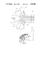
- FIG. 3 is a sectional view of the conveyor belt showing the grooves therein and the position of the conveyor divider plates relative thereto taken along the line 3--3 of FIG. 2.
- FIG. 4 is a partial side elevational view showing the conveyor end divider transition section.
- FIG. 5 is a partial sectional view showing the conveyor divider transition section.
- FIG. 6 is a partial sectional view showing the discharge section of the apparatus.
- FIG. 7 is a partial sectional view showing the distribution transition section of the invention.
- I indicates the infeed conveyor section comprising a conveyor belt which is divided into a plurality of sorting lanes into which the packages are initially placed for sortation
- II indicates an inclined conveyor section in tandem with the infeed conveyor and containing the same number of sortation lanes, and which functions to elevate the packages to a height to insure gravity flow movement in the part of the system past the conveyor belts
- III indicates a conveyor end divider transition section which functions to allow the packages to move from the conveyor belts to a plurality of discharge chutes aligned with the individual sortation lanes, the discharge chutes having an optimum angle of discharge.
- the conveyor end divider transition section is designed to allow easy access to the packages therein in the unlikely effect of a jam or failure of the packaging material.
- the conveyor end divider transition section is attached to the lane conveyors and integrates the conveyors to the discharge system and provides for a first change in direction of the conveyed packages at the optimum attitude for proper and consistent gravity flow.
- IV indicates a distribution transition section which provides for the distribution of the conveyed packages into the appropriate number of discharge points.
- the distribution transition section provides for the continued movement of the packages at the optimum attitude and angle for gravity flow and permits the downstream discharge chutes to be identical.
- V indicates the discharge section comprising a plurality of discharge chutes which permit the packages to be discharged into receptacles.
- the discharge chutes may be identical in design and dimension and allow the conveyed packages to be at the optimum attitude for proper handling.
- the discharge chutes also provide for the conveyed materials to be laid flat for stacking and subsequent handling. This lay down feature provides for the conveyed materials to always be orientated in the same direction for ease of label or identification reading.
- the apparatus of the present invention comprises an infeed conveyor generally designated by the numeral 10.
- the conveyor means 10 may be of substantially any typical construction known to those skilled in the art such as a belt-type conveyor having floor supports 11, a belt 12 for defining a package-supporting surface, and a plurality of driving and idler rollers 13 for driving and/or supporting the belt 12 in any manner apparent to those skilled in the art.
- the belt 12 may be driven in any manner apparent to those skilled in the art such as by way of a typical drive motor (not shown) to cause packages 14 thereon to move in the direction of the arrow 15.
- inclined conveyor 20 is positioned in tandem with the infeed conveyor 10 to receive the conveyed packages therefrom and to elevate the packages to a height sufficient to enable gravity to distribute the packages as hereinafter described.
- inclined conveyor 20 would not be needed in the event that the place of installation permitted the infeed conveyor 10 to be positioned at a sufficient height with respect to the divider transition section, conveyor divider transition section, and the discharge section whereby gravity would permit the distribution of the packages leaving the infeed conveyor.
- the inclined conveyor comprises floor supports 21, a belt 22 for defining a package-supporting conveyor surface, and a plurality of driving and idler rollers 23 for driving and supporting the belt 22 in a manner that will be apparent to those skilled in the art.
- the belt 22 may be driven in any manner apparent to those skilled in the art such as by way of a typical drive motor (not shown) to cause the packages 14 to move in the direction of the arrow 25.
- the conveyor surfaces 12 and 22 are divided into sort lanes by an adjustable six position conveyor divider plate apparatus comprising an adjustable height frame having a horizontal member 16, support members 17 and a plurality of dividers 18 which divide the conveyor surfaces into a plurality of sorting lanes.
- the conveyor surface 12 has grooves 19 therein which align with and receive the bottom ends of the dividers 18.
- the conveyor surface 22 of the inclined conveyor also has grooves therein (not shown) which align with and receive the bottom ends of the dividers 18 which are positioned above such grooves.
- the conveyor divider plate apparatus is vertically adjustable to allow the dividers to be adjusted downwardly to contact the belts to machine the grooves 19 in the surfaces 12 and 22 of the conveyor belts; or the grooves 19 may be machined by other appropriate means prior to assembly.
- the six position divider plates also are capable of longitudinal and horizontal movement with respect to the conveyor belt surfaces in order to adjust the divider plates to provide sort lanes having the desired width and eliminate spaces and cracks between the divider plates and the other parts of the system where packages might become jammed.
- the conveyor surface 12 is shown divided into eight (8) lanes by divider plates 18.
- Seven (7) of the lanes contain packages made from the material spunbonded olefin which has a tendency to become flimsy with repeated handling to form edges and ends such as illustrated at 14A, 14B and 14C which are susceptible to snagging between the divider plates and the conveyor belts in the prior art systems.
- the present invention avoids this problem by providing the grooves 19 in the conveyor belt which eliminates the cracks between the divider plates and the belts which was one of the places in the prior art systems where such packages became jammed and snagged.
- One (1) of the sort lanes contains a rigid package such as illustrated at 15.
- the end divider transition section indicated by III is shown in detail.
- the transition section between the conveyor surface and the distribution and discharge sections posed a problem because of the many potential jamming surfaces therein and because of the tendency for the packages to fail because of the handling.
- Jams and failures of the packages in the prior art systems at this point where particularly troublesome because of the delay and the inability to quickly clear such a jam.
- the present system avoids the problem of the prior art by providing a novel divider transition section which quickly and safely conveys the packaged material without exposing the packages to edges or crevices for snagging; and further, provides a convenient means for clearing a jam caused by failure of a package at this point.
- the conveyor end divider transition section is generally designated by the reference numeral 30 and is attached to the inclined conveyor 20 by means of a support structure 31 mounted on floor supports 21.
- the conveyor end divider transition section 30 provides a smooth transition without snags and jams for the conveyed items 14 from the inclined conveyor 20 to the distribution transition section IV hereinafter described.
- the conveyor end divider transition section 30 comprises an access plate 32 that is hinged to rotate to allow for easy access to the conveying path for maintenance and clearing of jams caused by a failure of the package material.
- the conveyor end divider transition section 30 is designed and constructed to allow the conveyed materials 14 to flow by means of gravity and is designed to maintain the optimum angle for package flow and prevention of jamming.
- the access plates 32 located in each sort lane are supported by, and are free to pivot around, an access plate pivot shaft 33.
- the access plates 32 are maintained in their normal operating position by an access plate support assembly 34.
- the support assemblies 34 are attached to a common pivot shaft assembly 35 and each support assembly 34 is individually adjustable. All of the support assemblies 34 are pivoted simultaneously by operating a spring-loaded pivot release handle 36, which is attached to the pivot shaft 35 by means of a yoke assembly 37.
- a distribution transition section generally designated by the reference numeral 40 is attached to the downstream end of the conveyor end divider transition section 30 to receive the packages flowing therefrom.
- the distribution transition section 40 consists of a plurality of chutes to receive the packages and convey the packages in a pre-determined geometric configuration to the discharge chutes 50 hereinafter described.
- the distribution transition section 40 is designed to provide for the optimum conveying angle for gravity flow of the packages with no points or crevices for snags or jams to occur, and also provides for the necessary direction changes to distribute the material to the individual discharge chutes 50.
- the distribution transition section 40 is connected at one end to the conveyor end divider transition section 30 and at the other end to the discharge chutes 50, and is supported by an adjustable support 42.
- the packages flow from the distribution transition section 40 to the individual discharge chutes 50 which allow the packages to continue flowing at the optimum conveying angle without snags and jams.
- the discharge chutes 50 have a "lay-down" device (not shown) to insure that the packages are properly aligned for speed of handling and recognition.
- the center lines of the discharge chutes 51, the distribution transition section chutes 41, the conveyor end transition section lanes and the sort lanes are aligned and are designated by the reference numeral 53.
- the conveyed and sorted packages 14 emerge from the ends 54 of the discharge chutes 51 where the packages can be either collected in a removable accumulation box (not shown) or can be deflected downward by means of a deflector (not shown) to be collected in a collection bag (not shown) as will be apparent to those skilled in the art.
- the present invention provides a new and useful conveyorized sorting and distribution apparatus which overcomes the problems of the prior art.
- the apparatus of the present invention introduces a six-position adjustable divider plate that allows for the creation of a custom groove in the belt to prevent jamming of flimsy envelope packaging material. This system of adjustment also allows for one common belt and driving means to be used to convey multiple packages simultaneously.
- the conveyor end divider transition section of the present invention makes possible the transition from the powered conveyor section to the gravity distribution transition section without jamming and allows steel materials to be used in the construction of the apparatus.
- This section also has the unique feature of access from the underside for maintenance through individually-adjustable access plates.
- the distribution transition section allows the maintenance of the proper and optimum angle for conveying. This transition section also allows distribution of the lanes so that equal spacing thereof is possible and identical chutes can be used. This distribution transition section makes possible the simultaneous change in direction in multiple planes.
- packages 14 will be placed on the belt 12 in the particular lane related to the destination of the package which will be conveyed in the direction of the arrow 15.
- the package will proceed in the direction of the arrow 15 along the infeed conveyor 10 onto the inclined conveyor 20 where it will proceed in the direction of the arrow 25 to the conveyor end divider transition section 30 where it will flow by gravity to the distribution transition section 40 where it continues to flow under the force of gravity and through the distribution transition chutes 41 and finally to the discharge chutes 51 to the receptacles at the ends thereof.
Landscapes
- Engineering & Computer Science (AREA)
- Mechanical Engineering (AREA)
- Branching, Merging, And Special Transfer Between Conveyors (AREA)
- Discharge Of Articles From Conveyors (AREA)
Abstract
A conveyorized sorting and distribution system for the handling of packages of documents or other items includes an infeed conveyor in tandem with an inclined conveyor and a plurality of vertically adjustable conveyor divider plates positioned above the infeed and inclined conveyors to divide the conveying surfaces into a plurality of individual sorting lanes. The infeed and inclined conveyor belts have a plurality of longitudinal grooves therein which may be created by and are aligned with the divider plates which extend into said grooves. A conveyor end divider transition section positioned at the end of the inclined conveyor enables the conveyed materials to flow by means by gravity to a distribution transition section that includes a chute for each lane of conveyed materials. The distribution transition section provides for the optimum conveying angle for gravity flow of the conveyed materials and also provides the necessary direction changes to distribute the materials to the desired discharge chute. A plurality of discharge chutes receive the conveyed materials at the end of the distribution transition section and discharges the conveyed materials into receptacles.
Description
This invention relates to apparatus for sorting, conveying and distributing items, and in particular to a sorting, conveying and distributing system for the handling of rigid or flexible packages of documents, or loosely packaged documents, and for allowing the positioning, distribution and accumulation of these packages for subsequent handling.
In recent years, the overnight courier and package delivery industry has grown to the point where the companies have a relatively short period of time to collect, sort and deliver hundreds of thousands of packages in order to meet the promised next day delivery deadline.
The industry quickly outgrew the capacity of manual sortation systems and attempted to adapt known sortation-conveyor systems to solve the enormous sorting and conveying work load. The prior art sorting and conveying systems comprised divided, multi-laned conveyors having separate belts and dividers which conveyed the packages to chutes that had to be configured to meet the needs of the conveyor system. The prior art apparatus was found to be inefficient and noneconomical with respect to an optimum layout for the use of man power and space. One specific complaint against adaptation of the prior art apparatus to the overnight package delivery industry was that the layout of the sorting-conveying apparatus was dictated by the equipment which required excessive space to accomplish the sortation-conveying process. Moreover, in order to prevent jamming of loosely packaged or flexible packages of documents, the prior art apparatus required multiple belt, complicated mechanical conveying systems which were uneconomical and inefficient with respect to the use of space, man power and cost. Another problem with the prior art systems was that they did not allow for the placing of the discharge and collection points in the best positions for the utilization of man power and space. See for example U.S. Patent Nos. 4,047,712; 3,032,211: 2,833,393; and 2,679,309 for prior art sorting-conveying systems having features which were adapted for use in the overnight package delivery industry with limited success.
Another problem resulting from the use of prior art sorting-conveying systems relates to the particular type of material used by numerous courier service companies to make their envelopes. The material is spun bonded olefin which is very strong and durable, but which becomes flimsy, pliable and dogeared with repeated handling whereby the envelope develops numerous edges or corners which are susceptible to catching on protrusions or in cracks while being conveyed. The prior art systems have numerous places and cracks where the edges and corners of such packages may catch and cause a jam. For example, the space between the lane dividers and the conveyor belts immediately below were a continuous source of jams and stoppages in the prior art systems. Also, the prior art systems were not designed to eliminate such cracks and other potential problem points where jams and stoppages could occur in the system between the conveyor belt and the collection point. The prior art systems had no convenient means for clearing a jam which occurred at points in the system past the conveyor surfaces.
Therefore, a need has developed for a sorting, conveying, and distributing system for the handling of packages which are susceptible to snagging on the conveyor surface and causing jams, or which are susceptible to failure whereby the contents will be spilled and cause a jam.
It is a general object of this invention to provide a conveying and sorting means for envelopes and packages made from spunbonded olefin, or other similar materials, without damage, jamming, or delay.
Another object of the invention is to provide a conveying and sorting system which is capable of handling envelopes or packages made from any flexible or rigid packaging material.
The new and improved conveyorized sorting and distribution system of the present invention comprises an infeed conveyor and an inclined conveyor in tandem and having a plurality of conveyor divider plates mounted above said conveyor surfaces for dividing said surfaces into a plurality of sorting lanes. The conveying surfaces have grooves therein immediately below the divider plates which extend into the grooves. A divider transition section conveys the packages from the inclined conveyor to a distribution transition section which introduces the packages to the individual discharge chutes where they are conveyed to receptacles.
The objects are accomplished by the configuration of the components, the design of the components, and the method of construction which prevent the packages from becoming jammed or in any other manner damaged or stuck in the apparatus for conveying and sorting. This invention has eliminated the points in the flow path of the conveyed packages where jamming might occur. The conveyor system provides for the packages to travel with no access to crevices and the gravity transition sections are constructed so that no jamming can occur.
FIG. 1 is a plan view of the conveyorized sorting and distribution system of the present invention.
FIG. 2 is a side elevational view of the invention.
FIG. 3 is a sectional view of the conveyor belt showing the grooves therein and the position of the conveyor divider plates relative thereto taken along the line 3--3 of FIG. 2.
FIG. 4 is a partial side elevational view showing the conveyor end divider transition section.
FIG. 5 is a partial sectional view showing the conveyor divider transition section.
FIG. 6 is a partial sectional view showing the discharge section of the apparatus.
FIG. 7 is a partial sectional view showing the distribution transition section of the invention.
Referring to FIG. 1, the five (5) basic sections of the conveyorized sorting and distribution system of the present invention are indicated as follows: I indicates the infeed conveyor section comprising a conveyor belt which is divided into a plurality of sorting lanes into which the packages are initially placed for sortation; II indicates an inclined conveyor section in tandem with the infeed conveyor and containing the same number of sortation lanes, and which functions to elevate the packages to a height to insure gravity flow movement in the part of the system past the conveyor belts; III indicates a conveyor end divider transition section which functions to allow the packages to move from the conveyor belts to a plurality of discharge chutes aligned with the individual sortation lanes, the discharge chutes having an optimum angle of discharge. The conveyor end divider transition section is designed to allow easy access to the packages therein in the unlikely effect of a jam or failure of the packaging material. The conveyor end divider transition section is attached to the lane conveyors and integrates the conveyors to the discharge system and provides for a first change in direction of the conveyed packages at the optimum attitude for proper and consistent gravity flow. IV indicates a distribution transition section which provides for the distribution of the conveyed packages into the appropriate number of discharge points. The distribution transition section provides for the continued movement of the packages at the optimum attitude and angle for gravity flow and permits the downstream discharge chutes to be identical. V indicates the discharge section comprising a plurality of discharge chutes which permit the packages to be discharged into receptacles. The discharge chutes may be identical in design and dimension and allow the conveyed packages to be at the optimum attitude for proper handling. The discharge chutes also provide for the conveyed materials to be laid flat for stacking and subsequent handling. This lay down feature provides for the conveyed materials to always be orientated in the same direction for ease of label or identification reading.
Referring to FIGS. 1 and 2, the apparatus of the present invention comprises an infeed conveyor generally designated by the numeral 10. The conveyor means 10 may be of substantially any typical construction known to those skilled in the art such as a belt-type conveyor having floor supports 11, a belt 12 for defining a package-supporting surface, and a plurality of driving and idler rollers 13 for driving and/or supporting the belt 12 in any manner apparent to those skilled in the art. The belt 12 may be driven in any manner apparent to those skilled in the art such as by way of a typical drive motor (not shown) to cause packages 14 thereon to move in the direction of the arrow 15.
II indicates an inclined conveyor which is positioned in tandem with the infeed conveyor 10 to receive the conveyed packages therefrom and to elevate the packages to a height sufficient to enable gravity to distribute the packages as hereinafter described. Of course, inclined conveyor 20 would not be needed in the event that the place of installation permitted the infeed conveyor 10 to be positioned at a sufficient height with respect to the divider transition section, conveyor divider transition section, and the discharge section whereby gravity would permit the distribution of the packages leaving the infeed conveyor.
The inclined conveyor comprises floor supports 21, a belt 22 for defining a package-supporting conveyor surface, and a plurality of driving and idler rollers 23 for driving and supporting the belt 22 in a manner that will be apparent to those skilled in the art. The belt 22 may be driven in any manner apparent to those skilled in the art such as by way of a typical drive motor (not shown) to cause the packages 14 to move in the direction of the arrow 25.
Referring to FIGS. 1, 2 and 3, the conveyor surfaces 12 and 22 are divided into sort lanes by an adjustable six position conveyor divider plate apparatus comprising an adjustable height frame having a horizontal member 16, support members 17 and a plurality of dividers 18 which divide the conveyor surfaces into a plurality of sorting lanes. The conveyor surface 12 has grooves 19 therein which align with and receive the bottom ends of the dividers 18. The conveyor surface 22 of the inclined conveyor also has grooves therein (not shown) which align with and receive the bottom ends of the dividers 18 which are positioned above such grooves. The conveyor divider plate apparatus is vertically adjustable to allow the dividers to be adjusted downwardly to contact the belts to machine the grooves 19 in the surfaces 12 and 22 of the conveyor belts; or the grooves 19 may be machined by other appropriate means prior to assembly. The six position divider plates also are capable of longitudinal and horizontal movement with respect to the conveyor belt surfaces in order to adjust the divider plates to provide sort lanes having the desired width and eliminate spaces and cracks between the divider plates and the other parts of the system where packages might become jammed.
Referring to FIG. 3, the conveyor surface 12 is shown divided into eight (8) lanes by divider plates 18. Seven (7) of the lanes contain packages made from the material spunbonded olefin which has a tendency to become flimsy with repeated handling to form edges and ends such as illustrated at 14A, 14B and 14C which are susceptible to snagging between the divider plates and the conveyor belts in the prior art systems. The present invention avoids this problem by providing the grooves 19 in the conveyor belt which eliminates the cracks between the divider plates and the belts which was one of the places in the prior art systems where such packages became jammed and snagged. One (1) of the sort lanes contains a rigid package such as illustrated at 15.
Referring now to FIGS. 4 and 5, the end divider transition section indicated by III is shown in detail. In prior art systems, the transition section between the conveyor surface and the distribution and discharge sections posed a problem because of the many potential jamming surfaces therein and because of the tendency for the packages to fail because of the handling. Jams and failures of the packages in the prior art systems at this point where particularly troublesome because of the delay and the inability to quickly clear such a jam. The present system avoids the problem of the prior art by providing a novel divider transition section which quickly and safely conveys the packaged material without exposing the packages to edges or crevices for snagging; and further, provides a convenient means for clearing a jam caused by failure of a package at this point.
The conveyor end divider transition section is generally designated by the reference numeral 30 and is attached to the inclined conveyor 20 by means of a support structure 31 mounted on floor supports 21. The conveyor end divider transition section 30 provides a smooth transition without snags and jams for the conveyed items 14 from the inclined conveyor 20 to the distribution transition section IV hereinafter described. The conveyor end divider transition section 30 comprises an access plate 32 that is hinged to rotate to allow for easy access to the conveying path for maintenance and clearing of jams caused by a failure of the package material. The conveyor end divider transition section 30 is designed and constructed to allow the conveyed materials 14 to flow by means of gravity and is designed to maintain the optimum angle for package flow and prevention of jamming.
The access plates 32 located in each sort lane are supported by, and are free to pivot around, an access plate pivot shaft 33. The access plates 32 are maintained in their normal operating position by an access plate support assembly 34. The support assemblies 34 are attached to a common pivot shaft assembly 35 and each support assembly 34 is individually adjustable. All of the support assemblies 34 are pivoted simultaneously by operating a spring-loaded pivot release handle 36, which is attached to the pivot shaft 35 by means of a yoke assembly 37.
A distribution transition section generally designated by the reference numeral 40 is attached to the downstream end of the conveyor end divider transition section 30 to receive the packages flowing therefrom. The distribution transition section 40 consists of a plurality of chutes to receive the packages and convey the packages in a pre-determined geometric configuration to the discharge chutes 50 hereinafter described. The distribution transition section 40 is designed to provide for the optimum conveying angle for gravity flow of the packages with no points or crevices for snags or jams to occur, and also provides for the necessary direction changes to distribute the material to the individual discharge chutes 50. The distribution transition section 40 is connected at one end to the conveyor end divider transition section 30 and at the other end to the discharge chutes 50, and is supported by an adjustable support 42.
The packages flow from the distribution transition section 40 to the individual discharge chutes 50 which allow the packages to continue flowing at the optimum conveying angle without snags and jams. The discharge chutes 50 have a "lay-down" device (not shown) to insure that the packages are properly aligned for speed of handling and recognition. The center lines of the discharge chutes 51, the distribution transition section chutes 41, the conveyor end transition section lanes and the sort lanes are aligned and are designated by the reference numeral 53.
The conveyed and sorted packages 14 emerge from the ends 54 of the discharge chutes 51 where the packages can be either collected in a removable accumulation box (not shown) or can be deflected downward by means of a deflector (not shown) to be collected in a collection bag (not shown) as will be apparent to those skilled in the art.
The inventor has discovered that there is a minimum conveying angle to insure that packages moving under the force of gravity in sections III, IV and V will flow freely and continuously. This angle is 25° as indicated by numeral 43 in FIG. 4.
It will thus be seen that the present invention provides a new and useful conveyorized sorting and distribution apparatus which overcomes the problems of the prior art. The apparatus of the present invention introduces a six-position adjustable divider plate that allows for the creation of a custom groove in the belt to prevent jamming of flimsy envelope packaging material. This system of adjustment also allows for one common belt and driving means to be used to convey multiple packages simultaneously.
The conveyor end divider transition section of the present invention makes possible the transition from the powered conveyor section to the gravity distribution transition section without jamming and allows steel materials to be used in the construction of the apparatus. This section also has the unique feature of access from the underside for maintenance through individually-adjustable access plates.
The distribution transition section allows the maintenance of the proper and optimum angle for conveying. This transition section also allows distribution of the lanes so that equal spacing thereof is possible and identical chutes can be used. This distribution transition section makes possible the simultaneous change in direction in multiple planes.
The use and operation of the conveyorized sorting and distribution system of the present invention will be apparent to those skilled in the art. In general, packages 14 will be placed on the belt 12 in the particular lane related to the destination of the package which will be conveyed in the direction of the arrow 15. The package will proceed in the direction of the arrow 15 along the infeed conveyor 10 onto the inclined conveyor 20 where it will proceed in the direction of the arrow 25 to the conveyor end divider transition section 30 where it will flow by gravity to the distribution transition section 40 where it continues to flow under the force of gravity and through the distribution transition chutes 41 and finally to the discharge chutes 51 to the receptacles at the ends thereof.
Although the invention has been described and illustrated with respect to a preferred embodiment thereof, it is not to be so limited since changes and modifications may be made therein which are within the full intended scope of the invention.
Claims (6)
1. Apparatus for sorting, conveying, and distributing packages comprising:
(a) An infeed conveyor having a belt which defines a package-supporting conveyor surface
(b) An inclined conveyor having a belt defining a package-supporting conveyor surface, said inclined conveyor being positioned in tandem and inclined with respect to said infeed conveyor;
(c) A divider plate assembly mounted above said infeed and inclined conveyors and having a plurality of divider plates extending longitudinally above said conveyor belts to divide said conveyor belts into a plurality of sort lanes: said divider plates being vertically adjustable with respect to said conveyor belts whereby said plates may be lowered to contact said conveyor belts to machine grooves therein;
(d) Conveyor end divider transition means having a sort lane aligned with each sort lane on said conveyor belts and positioned at the end of said inclined conveyor to receive packages conveyed thereon, said conveyor end divider transition section functioning to convey by gravity flow packages received from said inclined conveyor;
(e) Distribution transition means having a sort lane aligned with each sort lane in said conveyor end divider transition means and connected to said conveyor end divider transition means to receive packages conveyed therefrom and to convey by gravity flow such packages in pre-determined directions: and
(f) Discharge means having a chute aligned with each sort lane in said distribution transition means and connected to said distribution transition means to receive packages conveyed therefrom to convey by gravity flow packages received from said distribution transition section to desired locations.
2. The apparatus for sorting, conveying and distributing packages of claim 1 in which said infeed conveyor belt and said inclined conveyor belt have pre-formed longitudinal grooves therein; and wherein said divider plates are positioned above said longitudinal grooves and are lowered so that the lower edges of said plates fit within said grooves.
3. The apparatus for sorting, conveying and distributing packages of claim 1 wherein said conveyor end divider transition means, said distribution transition means, and said discharge means are designed to provide a minimum angle of 25° for the gravity fall of said packages.
4. The apparatus for sorting, conveying and distributing packages of claim 1 wherein each sort lane in said conveyor end divider transition means contains an access plate which may be opened to expose said sort lane.
5. The apparatus of claim 1 wherein said divider plate assembly comprises divider plates which are capable of vertical, horizontal and longitudinal movement with respect to said conveyor surfaces.
6. The apparatus of claim 1 wherein said discharge chutes deflect, align and stack each package in the same manner for speed of subsequent handling and recognition of the packages.
Priority Applications (2)
| Application Number | Priority Date | Filing Date | Title |
|---|---|---|---|
| US07/367,871 US4925002A (en) | 1989-06-19 | 1989-06-19 | Conveyorized sortation system |
| PCT/US1990/003373 WO1990015764A1 (en) | 1989-06-19 | 1990-06-19 | Conveyorized sortation system |
Applications Claiming Priority (1)
| Application Number | Priority Date | Filing Date | Title |
|---|---|---|---|
| US07/367,871 US4925002A (en) | 1989-06-19 | 1989-06-19 | Conveyorized sortation system |
Publications (1)
| Publication Number | Publication Date |
|---|---|
| US4925002A true US4925002A (en) | 1990-05-15 |
Family
ID=23448978
Family Applications (1)
| Application Number | Title | Priority Date | Filing Date |
|---|---|---|---|
| US07/367,871 Expired - Lifetime US4925002A (en) | 1989-06-19 | 1989-06-19 | Conveyorized sortation system |
Country Status (2)
| Country | Link |
|---|---|
| US (1) | US4925002A (en) |
| WO (1) | WO1990015764A1 (en) |
Cited By (18)
| Publication number | Priority date | Publication date | Assignee | Title |
|---|---|---|---|---|
| US5626101A (en) * | 1995-10-23 | 1997-05-06 | Kuhl; Jeffrey B. | Apparatus for continuous high speed loading of chicks into handling trays |
| US6152282A (en) * | 1999-02-01 | 2000-11-28 | Src Vision, Inc. | Laned conveyor belt |
| US6209707B1 (en) * | 1998-06-03 | 2001-04-03 | Ronchipack S.R.L. | Apparatus for adjusting the relative position of side-walls for guiding containers in machines for forming arrays of said containers |
| US20050205387A1 (en) * | 2004-03-11 | 2005-09-22 | Tritek Technologies, Inc. | Object transport & sorting assemblies & methods |
| US20080135464A1 (en) * | 2006-10-17 | 2008-06-12 | Lubezny Vadim A | Separating system for separating articles |
| CN100403014C (en) * | 2005-05-10 | 2008-07-16 | 浙江工业大学 | An online automatic monitoring device for stamping quality of crystal oscillator shell |
| US20090044642A1 (en) * | 2007-08-16 | 2009-02-19 | Woolley Randy P | Automated Sample Collection Apparatus |
| US20110067780A1 (en) * | 2009-09-21 | 2011-03-24 | Kellly John J | Apparatus for filling receptacles with granular material |
| CN105363690A (en) * | 2015-11-30 | 2016-03-02 | 大连海洋大学 | Photoelectric scallop sorting device |
| US9676561B1 (en) * | 2011-04-29 | 2017-06-13 | American Airlines, Inc. | Baggage cart handling system |
| CN108706321A (en) * | 2018-05-18 | 2018-10-26 | 江苏澳洋世家服装有限公司 | A kind of ring bobbin automatic arranging apparatus |
| CN109911548A (en) * | 2019-03-20 | 2019-06-21 | 深圳沸石科技股份有限公司 | A kind of patch production arranging-in-row device for putting and shunting conveying function with counnter attack |
| CN110328162A (en) * | 2019-07-09 | 2019-10-15 | 汪杉杉 | A kind of automatic material flow sorting palletizing system |
| CN113663925A (en) * | 2021-08-18 | 2021-11-19 | 天能电池集团(马鞍山)新能源科技有限公司 | Automatic matching conveying line for storage batteries and using method thereof |
| CN114408545A (en) * | 2020-10-28 | 2022-04-29 | 深圳顺丰泰森控股(集团)有限公司 | Sorting device, grid slot plate thereof and sorting method |
| CN114678313A (en) * | 2022-03-31 | 2022-06-28 | 先之科半导体科技(东莞)有限公司 | A multi-channel adjustable patch diode forwarding component |
| CN114887937A (en) * | 2022-05-25 | 2022-08-12 | 无锡图创智能科技有限公司 | 3D vision work piece sorting device and letter sorting snatchs mechanism thereof |
| CN117085950A (en) * | 2023-07-25 | 2023-11-21 | 广东信源物流设备有限公司 | An efficient logistics processing system and sorting method for small express parcels |
Citations (8)
| Publication number | Priority date | Publication date | Assignee | Title |
|---|---|---|---|---|
| FR1196499A (en) * | 1957-06-21 | 1959-11-24 | Siemens Ag | Device for placing missives in control position |
| GB824414A (en) * | 1957-04-18 | 1959-12-02 | Siemens Ag | Improvements in or relating to sorting machines for letters or the like |
| DE1105342B (en) * | 1957-11-12 | 1961-04-20 | Siemens Ag | Device for sorting out and feeding unordered items to forklifts |
| GB919716A (en) * | 1960-07-05 | 1963-02-27 | Vickers Armstrongs South Marst | Improvements in or relating to machines for sorting articles |
| US3083810A (en) * | 1960-12-28 | 1963-04-02 | Johnson Co Gordon | Giblet conveyor |
| US3554353A (en) * | 1968-09-18 | 1971-01-12 | Emhart Corp | Adjustable lane guides |
| US4162727A (en) * | 1977-10-26 | 1979-07-31 | Fabreeka Products Company | Conveyor belt |
| US4337866A (en) * | 1980-07-28 | 1982-07-06 | Acme Visible Records, Inc. | Mail sorting apparatus and system |
Family Cites Families (1)
| Publication number | Priority date | Publication date | Assignee | Title |
|---|---|---|---|---|
| US308310A (en) * | 1884-11-18 | ewers |
-
1989
- 1989-06-19 US US07/367,871 patent/US4925002A/en not_active Expired - Lifetime
-
1990
- 1990-06-19 WO PCT/US1990/003373 patent/WO1990015764A1/en not_active Ceased
Patent Citations (8)
| Publication number | Priority date | Publication date | Assignee | Title |
|---|---|---|---|---|
| GB824414A (en) * | 1957-04-18 | 1959-12-02 | Siemens Ag | Improvements in or relating to sorting machines for letters or the like |
| FR1196499A (en) * | 1957-06-21 | 1959-11-24 | Siemens Ag | Device for placing missives in control position |
| DE1105342B (en) * | 1957-11-12 | 1961-04-20 | Siemens Ag | Device for sorting out and feeding unordered items to forklifts |
| GB919716A (en) * | 1960-07-05 | 1963-02-27 | Vickers Armstrongs South Marst | Improvements in or relating to machines for sorting articles |
| US3083810A (en) * | 1960-12-28 | 1963-04-02 | Johnson Co Gordon | Giblet conveyor |
| US3554353A (en) * | 1968-09-18 | 1971-01-12 | Emhart Corp | Adjustable lane guides |
| US4162727A (en) * | 1977-10-26 | 1979-07-31 | Fabreeka Products Company | Conveyor belt |
| US4337866A (en) * | 1980-07-28 | 1982-07-06 | Acme Visible Records, Inc. | Mail sorting apparatus and system |
Cited By (25)
| Publication number | Priority date | Publication date | Assignee | Title |
|---|---|---|---|---|
| US5626101A (en) * | 1995-10-23 | 1997-05-06 | Kuhl; Jeffrey B. | Apparatus for continuous high speed loading of chicks into handling trays |
| US6209707B1 (en) * | 1998-06-03 | 2001-04-03 | Ronchipack S.R.L. | Apparatus for adjusting the relative position of side-walls for guiding containers in machines for forming arrays of said containers |
| US6152282A (en) * | 1999-02-01 | 2000-11-28 | Src Vision, Inc. | Laned conveyor belt |
| US20050205387A1 (en) * | 2004-03-11 | 2005-09-22 | Tritek Technologies, Inc. | Object transport & sorting assemblies & methods |
| US7185748B2 (en) * | 2004-03-11 | 2007-03-06 | Tritek Technologies, Inc. | Object transport and sorting assemblies and methods |
| CN100403014C (en) * | 2005-05-10 | 2008-07-16 | 浙江工业大学 | An online automatic monitoring device for stamping quality of crystal oscillator shell |
| US20080135464A1 (en) * | 2006-10-17 | 2008-06-12 | Lubezny Vadim A | Separating system for separating articles |
| US20090044642A1 (en) * | 2007-08-16 | 2009-02-19 | Woolley Randy P | Automated Sample Collection Apparatus |
| US7721897B2 (en) * | 2007-08-16 | 2010-05-25 | Kennecott Utah Copper Llc | Automated sample collection apparatus |
| US20110067780A1 (en) * | 2009-09-21 | 2011-03-24 | Kellly John J | Apparatus for filling receptacles with granular material |
| US9701483B1 (en) | 2011-04-29 | 2017-07-11 | American Airlines, Inc. | Baggage cart handling system |
| US9676561B1 (en) * | 2011-04-29 | 2017-06-13 | American Airlines, Inc. | Baggage cart handling system |
| US10507983B1 (en) | 2011-04-29 | 2019-12-17 | American Airlines, Inc. | Baggage cart handling system |
| CN105363690A (en) * | 2015-11-30 | 2016-03-02 | 大连海洋大学 | Photoelectric scallop sorting device |
| CN108706321A (en) * | 2018-05-18 | 2018-10-26 | 江苏澳洋世家服装有限公司 | A kind of ring bobbin automatic arranging apparatus |
| CN108706321B (en) * | 2018-05-18 | 2024-05-03 | 冠县云鑫纺织有限公司 | Automatic spun yarn tube placing device |
| CN109911548A (en) * | 2019-03-20 | 2019-06-21 | 深圳沸石科技股份有限公司 | A kind of patch production arranging-in-row device for putting and shunting conveying function with counnter attack |
| CN110328162B (en) * | 2019-07-09 | 2021-02-09 | 苏州快捷智能科技有限公司 | Automatic sorting and stacking system for material flows |
| CN110328162A (en) * | 2019-07-09 | 2019-10-15 | 汪杉杉 | A kind of automatic material flow sorting palletizing system |
| CN114408545A (en) * | 2020-10-28 | 2022-04-29 | 深圳顺丰泰森控股(集团)有限公司 | Sorting device, grid slot plate thereof and sorting method |
| CN113663925A (en) * | 2021-08-18 | 2021-11-19 | 天能电池集团(马鞍山)新能源科技有限公司 | Automatic matching conveying line for storage batteries and using method thereof |
| CN114678313A (en) * | 2022-03-31 | 2022-06-28 | 先之科半导体科技(东莞)有限公司 | A multi-channel adjustable patch diode forwarding component |
| CN114678313B (en) * | 2022-03-31 | 2023-03-24 | 先之科半导体科技(东莞)有限公司 | Multichannel adjustable patch diode righting assembly |
| CN114887937A (en) * | 2022-05-25 | 2022-08-12 | 无锡图创智能科技有限公司 | 3D vision work piece sorting device and letter sorting snatchs mechanism thereof |
| CN117085950A (en) * | 2023-07-25 | 2023-11-21 | 广东信源物流设备有限公司 | An efficient logistics processing system and sorting method for small express parcels |
Also Published As
| Publication number | Publication date |
|---|---|
| WO1990015764A1 (en) | 1990-12-27 |
Similar Documents
| Publication | Publication Date | Title |
|---|---|---|
| US4925002A (en) | Conveyorized sortation system | |
| EP3117910B1 (en) | A method for culling flat packages and use | |
| US5695071A (en) | Small flats sorter | |
| EP2882650B1 (en) | Parcel handling method | |
| US4527937A (en) | Automatic storage and distribution system | |
| US6401936B1 (en) | Divert apparatus for conveyor system | |
| CN105873839B (en) | Separator Conveyor System for Big Bags in Rigid and Small Bags | |
| EP0565498B1 (en) | Methods and apparatus for conveying packages in a manner minimizing jams | |
| US8376118B2 (en) | Matrix sorter system | |
| KR102248689B1 (en) | Package Sorter For Ununiformed Freight | |
| CN109863103B (en) | Shunting chute in sorting and conveying system | |
| US20090242356A1 (en) | Matrix Sorter System With Transpositor Conveyor | |
| US20190031450A1 (en) | Article sorter with active discharge | |
| US3837469A (en) | Product orienting apparatus for packaging | |
| US6439367B1 (en) | Bowl diverter | |
| US20140041991A1 (en) | Checking station, separating device and method for separating piece goods | |
| US3752293A (en) | Article grouping system | |
| US20250066128A1 (en) | Sorting conveyor system | |
| US6564922B1 (en) | Flex diverter | |
| EP3870528B1 (en) | Positive displacement sorter with parallel divert and diagonal discharge | |
| KR102853804B1 (en) | Apparatus For Conveying Products Having Diverting Portion | |
| US3325005A (en) | Tableware sorter | |
| KR20260028422A (en) | Package sorting device | |
| EP4455058A1 (en) | Commissioning installation |
Legal Events
| Date | Code | Title | Description |
|---|---|---|---|
| STCF | Information on status: patent grant |
Free format text: PATENTED CASE |
|
| FEPP | Fee payment procedure |
Free format text: PAYOR NUMBER ASSIGNED (ORIGINAL EVENT CODE: ASPN); ENTITY STATUS OF PATENT OWNER: SMALL ENTITY |
|
| REMI | Maintenance fee reminder mailed | ||
| FPAY | Fee payment |
Year of fee payment: 4 |
|
| SULP | Surcharge for late payment | ||
| REMI | Maintenance fee reminder mailed | ||
| FPAY | Fee payment |
Year of fee payment: 8 |
|
| SULP | Surcharge for late payment | ||
| FPAY | Fee payment |
Year of fee payment: 12 |