US491971A - Coin controlled dice throwing machine - Google Patents
Coin controlled dice throwing machine Download PDFInfo
- Publication number
- US491971A US491971A US491971DA US491971A US 491971 A US491971 A US 491971A US 491971D A US491971D A US 491971DA US 491971 A US491971 A US 491971A
- Authority
- US
- United States
- Prior art keywords
- rod
- arm
- dice
- box
- throwing machine
- Prior art date
- Legal status (The legal status is an assumption and is not a legal conclusion. Google has not performed a legal analysis and makes no representation as to the accuracy of the status listed.)
- Expired - Lifetime
Links
- 239000011435 rock Substances 0.000 description 23
- 241000282693 Cercopithecidae Species 0.000 description 13
- 210000003414 extremity Anatomy 0.000 description 8
- 210000003141 lower extremity Anatomy 0.000 description 5
- 239000003795 chemical substances by application Substances 0.000 description 2
- 210000001364 upper extremity Anatomy 0.000 description 2
- 241000507564 Aplanes Species 0.000 description 1
- 241000294754 Macroptilium atropurpureum Species 0.000 description 1
- 102100027069 Odontogenic ameloblast-associated protein Human genes 0.000 description 1
- 101710091533 Odontogenic ameloblast-associated protein Proteins 0.000 description 1
- 238000010276 construction Methods 0.000 description 1
- 230000000994 depressogenic effect Effects 0.000 description 1
- 238000002349 difference gel electrophoresis Methods 0.000 description 1
- 230000000694 effects Effects 0.000 description 1
- 239000000463 material Substances 0.000 description 1
- 239000002184 metal Substances 0.000 description 1
- 210000000707 wrist Anatomy 0.000 description 1
Images


Classifications
-
- G—PHYSICS
- G07—CHECKING-DEVICES
- G07F—COIN-FREED OR LIKE APPARATUS
- G07F5/00—Coin-actuated mechanisms; Interlocks
- G07F5/02—Coin-actuated mechanisms; Interlocks actuated mechanically by coins, e.g. by a single coin
Definitions
- w mam: mins 00.. wnmaumu. wAsHmumn. n. 4;
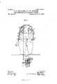
- Figure 1 is a sectional elevation of the machine including a view of the left side of the monkey.
- Fig. 2 is a sectional elevation comprising parts of the other side of the monkey.
- Fig. 3 is a sectional elevation taken parallel with the front of the monkey.
- Fig. 4 is aplan of certain parts.
- Figs. 5, 6 and 7 are enlarged detail views of the motor mechanism.
- the machine consists essentially of a motor mechanism controlled by a coin receptacle, a movable table or platform, a monkey having one arm movable for the purpose of alternately tilting the table and returning it to a horizontal. position, and another arm having the dice box and movable-to shake the dice within the box, subsequently empty the box over the table and finally hold the box below the table so. that upon ,the tilting of the table the dice will drop back into the box.
- the body D of the monkey may be made of cast metal or of any other suitable material and of any desired configuration to represent wearing apparel. It is mounted upon and secured to the box or case B.
- the head is not in the present instance intended to be movable. Indeed, as here shown, none of the parts of the monkey are movable except the arms.
- This rod is immovable.
- a lower limb consisting of a rod 61 is pivoted by means of a pin 01 passing through the same.
- a rock shaft d is journaled in a fixed portion of the body D of the monkey, as here shown in bearings fastened to the cross piece 01
- This rock shaft has two arms d 61
- the arm d has a pivotal or loose connection with a rod 6 extending from the motor mechanism, said rod serving when actuated by the motor mechanism to transmit an oscillating motion to the rock shaft.
- the arm 01 of the rock shaft has a pivotal or'loose connection with one end of a rod (i which, at the other end is connected with the rod or limb d considerably forward of the pivot pin 01) It will be readily understood that when the rock shaft is oscillated in such direction that its arms (1 will be swung upward the rod or limb d will be swung upward, and as this is connected with the left side of the table, that this side of the table will be elevated and the right side depressed. The left hand at is connected with thetable and has a swinging connection with the rod 01 so as to adapt itself to the tilting of the table.
- the joints between the rods d and d and between the rod 61 and the rod d will be sufficiently loose to enable the rod 01 to swing laterally to compensate for the versed sine of the are through which the left side of the table moves.
- the swivel connection between the hand and the rod d may be made in any desirable manner, as for instance by circumferentially grooving the rod or a cylindric block attached to the rod, forming a cylindric socket in the wrist extending from the hand and inserting apin or screw through the socket into said groove.
- the right arm has an upper limb consisting mainly of a rod 61 which is rigidly connected in any suitable manner to the body D, as for instance by screws passing through it and engaging with the cross piece (1 of the body.
- This rod d like the rod d, is immovable.
- the lower limb of this arm consists of a rod cl pivotally connected by a pin (1 to the rod (Z in such manner as to be free to swing upward and downward.
- (Z is a rock shaft journaled in the body D, in the present instance in bearings attached to the cross piece (1 It has two arms (Z (Z).
- the arm (1 has a pivotal or loose connection with a rod e which is actuated by the motor mechanism to oscillate the rock shaft.
- the arm (Z has a pivotal or loose connection with one end of a rod (Z which at the other end has a pivotal or loose connection with the limb or rod d at a point considerably forward of the pin (Z connecting this rod or limb with the rod (Z Whenever the rod 0 is raised and the rock shaft is in consequence thereof oscillated in such direction as to swing upward the arm (1 the latter through the rod (1 will swing the'rod or limb (Z upward.
- the dice box D will be elevated above the table top. Vhen the rod 6 is lowered the rod or limb (Z will be lowered sufficiently for the box to receive the dice as they leave the tilted table top.
- the right hand which holds the dice box is fixedly secured upon a rock shaft (1 which is journaled in bearings that are secured to the rod or limb d.
- This rock shaft (1 is provided with an arm (Z which has a pivotal or loose connection with one end of a rod (1 whose upper end has a pivotal or loose connection with an arm (Z extending from a rock shaft (Z journaled in the body D, in the present instance in bearings secured upon the cross piece (Z).
- the rock shaft (Z is also provided with an arm (Z and the latter has a pivotal or loose connection with one end of a rod 6 actuated by the motor mechanism.
- the rods e e c are operated by cams c c c affixed to a shaft 0 journaled in plates 0 c comprised in the motor mechanism.
- On this shaft 0 is affixed a gear wheel 0 which engages with a pinion c affixed to a shaft 0 journaled in the plates 0 0
- the shaft 0 has affixed to it a gear wheel 0 which engages with a pinion e mounted upon a shaft 0 that is journaled in the plates 0 c and has affixed to it a worm wheel or star wheel 0 that engages with a worm 0 whose shaft is journaled in brackets secured to the plate 0 and is provided with a fan. In this way, the shaft 0 is retarded.
- a drum o around which is wound a chain or cord 0*, at whose lower end may be attached a motor weight.
- This drum has attached to it a pinion 0 and a ratchet wheel c, the latter engaging with a pawl 0 pivot-ally connected to the gear wheel 0 and so arranged that when the chain or cord is unwinding motion will be imparted by the drum to the said gear wheel 0 and consequently to the shaft 0 and the cams c c c and that when the drum is 1'0- tated in a direction to wind the chain or cord up no motion will be imparted to the shaft 0 or its appurtenances.
- the pinion c engages with a segment lever 0 fulcrumed to the plates 0 c Opposite one arm of this lever a slider bar G is arranged and it extends from the inside to the outside of the box B.
- the slider bar When the slider bar is moved inward it will oscillate the segment lever and rotate the drum in such direction as to wind up the chain or cord and raise the weight. Afterward, providing the motor mechanism shall be released for action, the weight will descend and operate the motor mechanism and through the latter move the monkey and table.
- the shaft 0 has affixed to it a disk 0 having in its periphery a notch with which may engage a pin h on a lever H fulcrumed between its ends by a pin it to one of the plates of the motor mechanism or to any other support in the box 13. WVhen the pin engages with said notch the motor mechanism will be stopped.
- the other end of the lever H is provided with a coin receptacle over which extends a chute J leading from the outside of the box B. When a coin of the proper denomination is dropped into the coin recepta cle the lever H will be oscillated and the motor mechanism released.
- the motor is stopped when the coin receptacle returns to its normal position.
- a tilting table a rod movable up and down to tilt the table and return it to its normal position
- a cam for moving said rod up and down, substantially as specified.
- a tilting table a rod movable up and down to tilt the table and return it to its nor-X mal position, a swiveling connection between said rod and the table, and a cam for moving said rod up and down, substantially as specified.
- a tilting table a rod d, a rod d pivotally connected to the rod d, a hand (1 connected to the table and having a swiveling connection with the rod (1 a rock shaft 01 having arms (1 01 a rod 01 extending between the arm 01 and the rod (1 and a rod e connected to the arm (1 substantially as specified.
- a tilting table a dice box
- a rod serving to support the dice box
- a cam for moving said rod up and down
- a rock shaft journaled on said rod and forming a connection between said rod and dice box and a second cam for oscillating this rock shaft, substantially as specified.
- a dice throwing machine the combination of a figure representing a living creature, movable arms, a tilting table connected with one of the arms and a dice box connected to the other arm, substantially as specified.
- a dice throwing machine the combination of a figure representing a living creature, movable arms, a tilting table connected with. one of the arms, a dice box connected to the other arm, motor mechanism for operating the arms and a coin receptacle for controlling the motor mechanism, substantially as specified.
- a motor mechanism comprising a main shaft, a drum connected to the shaft to impart motion thereto in one direction but to .run free vertically in the other direction, a
Landscapes
- Physics & Mathematics (AREA)
- General Physics & Mathematics (AREA)
- Toys (AREA)
Description
(No Model.) 4 Sheets-Sheet 1. P. G- WILLIAMS 8n A W, ROOVERS.
' GOIN UONTROLLED DIGE' THROWING MACHINE.
No. 491,971. Patented Feb. 14, 1893.
l x J I I 35 11%; awe anew EYERS CO, FNOYOJJTHM WEHiNGTDf. 0- C4 (No Model.) 4- Shets-Shet .2.
P. G. WILLIAMS & A. W. ROOVERS. GOIN CONTROLLED DIGB THROWING MAGHINE.
No. 491,971. Patented Feb. 14,1893.
gym vbow 4100 if m aa kfauwm "m: uonms PE ERS 00.. mun-(0.. wmmutau. n. I;
. 4 Sheets-Sheet 3. P.' G. WILLIAMS .& A W. RUDY HRS. COIN CONTROLLED DICE THROWING MACHINE- NO. 491,971. Patented Feb. 14, 1893- (No Model.)
w: mam: mins 00.. wnmaumu. wAsHmumn. n. 4;
(No Model.) 4 Sheets-8heet 4.
P G. WILLIAMS 8?: A. w. ROOVERS. COIN GONTROLLED DICE THROWING MACHINE;
No. 491,971. v Patented Feb. 14, 1893. /////////////J/ Wa e/way a aayva wtozw. v atrO'Z/HQ/WW z r "m: nonms PETERS 00.. PHCTO-UTHQ. WASNINGTON. n. c.
FFICEQ PEROY G. WILLIAMS AND ALFRED W. ROOVERS, OF BROOKLYN, NEW YORK; SAID ROOVERS ASSIGNOR TO SAID WILLIAMS.
COIN-CONTROLLED DICE-TH ROWING MACHINE.
SPECIFICATION forming part of Letters Patent No. 491,971, dated February 14, 1893.
Application filed December 26, 1889. Serial No. 334,948- (No model.)
To all whom it may concern.-
Be it known that we, PERCY G. WILLIAMS and ALFRED W. RoovERs, both of Brooklyn, Kings county, and State of New York, have invented a certain new and useful Improvement in Coin-Controlled Dice-Throwing Machines, of which the following is a specification.
We will describe a machine embodying the improvement and then point. out the novel features in the claims.
In the accompanying drawings, the machine is represented as comprising a figure representing a monkey.
Figure 1 is a sectional elevation of the machine including a view of the left side of the monkey. Fig. 2 is a sectional elevation comprising parts of the other side of the monkey. Fig. 3 is a sectional elevation taken parallel with the front of the monkey. Fig. 4is aplan of certain parts. Figs. 5, 6 and 7 are enlarged detail views of the motor mechanism.
Similar letters of reference designate corresponding parts in all the figures.
It may conduce to a clear understanding of the particular machine illustrated to premise that the machine consists essentially of a motor mechanism controlled by a coin receptacle, a movable table or platform, a monkey having one arm movable for the purpose of alternately tilting the table and returning it to a horizontal. position, and another arm having the dice box and movable-to shake the dice within the box, subsequently empty the box over the table and finally hold the box below the table so. that upon ,the tilting of the table the dice will drop back into the box.
A designates the table. Itis shown as consisting of a top a pivotally connected or.
' the latter being in the present example of our improvement designated by the letter D and held in the right hand of the monkey. The table top is tilted by a movement of the left arm of the monkey, the left hand being connected with the left side of the table top.
The body D of the monkey may be made of cast metal or of any other suitable material and of any desired configuration to represent wearing apparel. It is mounted upon and secured to the box or case B. The head is not in the present instance intended to be movable. Indeed, as here shown, none of the parts of the monkey are movable except the arms.
We will begin a description'of-the mechanism of the monkey at the left arm. This has an upper limb comprising a rod 01 which is v fastened in any suitable manner, as for instance, by screws d to a fixed part of the body D of the monkey, in the present instance, to a cross piece d in said body. This rod is immovable. To its lower end a lower limb consisting of a rod 61 is pivoted by means of a pin 01 passing through the same. A rock shaft d is journaled in a fixed portion of the body D of the monkey, as here shown in bearings fastened to the cross piece 01 This rock shaft has two arms d 61 The arm d has a pivotal or loose connection with a rod 6 extending from the motor mechanism, said rod serving when actuated by the motor mechanism to transmit an oscillating motion to the rock shaft. The arm 01 of the rock shaft has a pivotal or'loose connection with one end of a rod (i which, at the other end is connected with the rod or limb d considerably forward of the pivot pin 01 It will be readily understood that when the rock shaft is oscillated in such direction that its arms (1 will be swung upward the rod or limb d will be swung upward, and as this is connected with the left side of the table, that this side of the table will be elevated and the right side depressed. The left hand at is connected with thetable and has a swinging connection with the rod 01 so as to adapt itself to the tilting of the table. The joints between the rods d and d and between the rod 61 and the rod d will be sufficiently loose to enable the rod 01 to swing laterally to compensate for the versed sine of the are through which the left side of the table moves. The swivel connection between the hand and the rod d may be made in any desirable manner, as for instance by circumferentially grooving the rod or a cylindric block attached to the rod, forming a cylindric socket in the wrist extending from the hand and inserting apin or screw through the socket into said groove.
Before taking up the details of the motor mechanism, we will explain the construction of the right arm. It has an upper limb consisting mainly of a rod 61 which is rigidly connected in any suitable manner to the body D, as for instance by screws passing through it and engaging with the cross piece (1 of the body. This rod d like the rod d, is immovable. The lower limb of this arm consists of a rod cl pivotally connected by a pin (1 to the rod (Z in such manner as to be free to swing upward and downward.
(Z is a rock shaft journaled in the body D, in the present instance in bearings attached to the cross piece (1 It has two arms (Z (Z The arm (1 has a pivotal or loose connection with a rod e which is actuated by the motor mechanism to oscillate the rock shaft. The arm (Z has a pivotal or loose connection with one end of a rod (Z which at the other end has a pivotal or loose connection with the limb or rod d at a point considerably forward of the pin (Z connecting this rod or limb with the rod (Z Whenever the rod 0 is raised and the rock shaft is in consequence thereof oscillated in such direction as to swing upward the arm (1 the latter through the rod (1 will swing the'rod or limb (Z upward. In this way, the dice box D will be elevated above the table top. Vhen the rod 6 is lowered the rod or limb (Z will be lowered sufficiently for the box to receive the dice as they leave the tilted table top. The right hand which holds the dice box is fixedly secured upon a rock shaft (1 which is journaled in bearings that are secured to the rod or limb d. The rear end of this rock shaft (1 is provided with an arm (Z which has a pivotal or loose connection with one end of a rod (1 whose upper end has a pivotal or loose connection with an arm (Z extending from a rock shaft (Z journaled in the body D, in the present instance in bearings secured upon the cross piece (Z The rock shaft (Z is also provided with an arm (Z and the latter has a pivotal or loose connection with one end of a rod 6 actuated by the motor mechanism.
Before entering upon a detailed description of the motor mechanism, we will explain that the movements of therods e e e are so timed that while the left arm is holding the table in an approximately horizontal position, the lower limb of the right arm will be elevated to a point considerably above the table. \Vhile said limb is in this position, the right hand will be oscillated several times laterally to shake up the dice in the dice box. Subsequently the hand will be oscillated a considerably greater distance inward to effect the deposit of the dice upon the table, and after this the lower limb of the right arm will be lowered. The right hand will be oscillated to tilt the dice box toward the table and the lower limb of the left arm will be raised to tilt the table toward the dice box.
The rods e e c are operated by cams c c c affixed to a shaft 0 journaled in plates 0 c comprised in the motor mechanism. On this shaft 0 is affixed a gear wheel 0 which engages with a pinion c affixed to a shaft 0 journaled in the plates 0 0 The shaft 0 has affixed to it a gear wheel 0 which engages with a pinion e mounted upon a shaft 0 that is journaled in the plates 0 c and has affixed to it a worm wheel or star wheel 0 that engages with a worm 0 whose shaft is journaled in brackets secured to the plate 0 and is provided with a fan. In this way, the shaft 0 is retarded.
On the shaft 0 is loosely mounted a drum o around which is wound a chain or cord 0*, at whose lower end may be attached a motor weight. This drum has attached to it a pinion 0 and a ratchet wheel c, the latter engaging with a pawl 0 pivot-ally connected to the gear wheel 0 and so arranged that when the chain or cord is unwinding motion will be imparted by the drum to the said gear wheel 0 and consequently to the shaft 0 and the cams c c c and that when the drum is 1'0- tated in a direction to wind the chain or cord up no motion will be imparted to the shaft 0 or its appurtenances. The pinion c engages with a segment lever 0 fulcrumed to the plates 0 c Opposite one arm of this lever a slider bar G is arranged and it extends from the inside to the outside of the box B. A spring 9 coiled around it and engaging at one end with it and at the other end with the box B or an appurtenance thereof, serves to move the slider bar outward when it is not otherwise actuated. When the slider bar is moved inward it will oscillate the segment lever and rotate the drum in such direction as to wind up the chain or cord and raise the weight. Afterward, providing the motor mechanism shall be released for action, the weight will descend and operate the motor mechanism and through the latter move the monkey and table.
It is not necessary to describe the shapes of the cams c c c as they are fully shown in the drawings and we have already intimated what their contour should be by stating the movements which they are to impart to the rods 6 e 6 The shaft 0 has affixed to it a disk 0 having in its periphery a notch with which may engage a pin h on a lever H fulcrumed between its ends by a pin it to one of the plates of the motor mechanism or to any other support in the box 13. WVhen the pin engages with said notch the motor mechanism will be stopped. The other end of the lever H is provided with a coin receptacle over which extends a chute J leading from the outside of the box B. When a coin of the proper denomination is dropped into the coin recepta cle the lever H will be oscillated and the motor mechanism released.
0 is an arm or projection on the shaft 0, designed to contact with the extended end of the pin h, on the lever H, after the wheel 0 shall have made one revolution and the pin falls back into the notch in said wheel. By this means the motor is stopped when the coin receptacle returns to its normal position.
What we claim as our invention, and desire to secure by Letters Patent, is
1. In a dice throwing machine, the combination of a tilting table and a dice box movable independently of the table from a point above to a point below the table, substantially as specified.
2. In a dice throwing machine, the combination of a tilting table, a rod movable up and down to tilt the table and return it to its normal position, and a cam for moving said rod up and down, substantially as specified.
3. In a dice throwing machine, the combination of a tilting table, a rod movable up and down to tilt the table and return it to its nor-X mal position, a swiveling connection between said rod and the table, and a cam for moving said rod up and down, substantially as specified.
4. In a dice throwing machine, the combination of a tilting table, arod d, a rock shaft 01 having arms 01 d, a rod (1 pivotally connected to the rod d, a rod d extending between the arm 01 and the rod d and a rod e connected to the arm d substantially as specified.
5. In a dice throwing machine, the combination of a tilting table, a rod d, a rod d pivotally connected to the rod d, a hand (1 connected to the table and having a swiveling connection with the rod (1 a rock shaft 01 having arms (1 01 a rod 01 extending between the arm 01 and the rod (1 and a rod e connected to the arm (1 substantially as specified.
6. In a dice throwing machine, thecombination of a tilting table, a rod (1, a rock shaft d having arms 01 01 a rod d pivotally connected to the rod d, a rod d extending between the arm cl and the rod (i a rod 6 connected to the arm d and a cam for operating said rod 6', substantially as specified.
7. In a dice throwing machine, the combination of a tilting table, a dice box, a rod serving to support the dice box and a cam for moving said rod up and down, substantially as specified.
8. In a dice throwing machine, the combination of a tilting table, a dice box, a rod serving to support the dice box, a cam for moving said rod up and down, a rock shaft journaled on said rod and forming a connection between said rod and dice box and a second cam for oscillating this rock shaft, substantially as specified.
9. In a dice throwing machine, the combination of a rod @1 a rod d pivotally connected thereto, a rock shaft 01 having arms 01 and d, a rod (Z connecting the arm 61 with the rod (1 and a cam for operating the rock shaft (1, substantially as specified.
10. In a dice throwing machine, the combination of rod d rod d pivotally connected to the rod al a rock shaftd having an arin c1 rods d connecting the arm 61 with the rod d, a rock shaft d journaled on the rod d, a rock shaft 01 having an, arm (Z and a rod (Z connecting the arm 01 with an arm extending from the rock shaft d",-substan-- tially as specified.
11. In a dice throwing machine, the combination of a figure representing a living creature, movable arms, a tilting table connected with one of the arms and a dice box connected to the other arm, substantially as specified.
12. In a dice throwing machine, the combination of a figure representing a living creature, movable arms, a tilting table connected with. one of the arms, a dice box connected to the other arm, motor mechanism for operating the arms and a coin receptacle for controlling the motor mechanism, substantially as specified.
13. In a coin controlled machine, the combination of a motor mechanism comprising a main shaft, a drum connected to the shaft to impart motion thereto in one direction but to .run free vertically in the other direction, a
motive agent connected with the drum, a segment lever for rotating the drum in the reverse direction to that in which it is rotated by the motive agent and a slider bar for operating the segment lever, substantially as specified. v
PERCY G. WILLIAMS. ALFRED W. ROOVERS. Witnesses:
EDWIN I-I. BROWN, 0. R. FERGUSON.
Publications (1)
| Publication Number | Publication Date |
|---|---|
| US491971A true US491971A (en) | 1893-02-14 |
Family
ID=2560815
Family Applications (1)
| Application Number | Title | Priority Date | Filing Date |
|---|---|---|---|
| US491971D Expired - Lifetime US491971A (en) | Coin controlled dice throwing machine |
Country Status (1)
| Country | Link |
|---|---|
| US (1) | US491971A (en) |
Cited By (7)
| Publication number | Priority date | Publication date | Assignee | Title |
|---|---|---|---|---|
| US3831948A (en) * | 1972-04-24 | 1974-08-27 | Yoshi Ito | Automatic dice shaking device |
| US20080048394A1 (en) * | 2006-08-23 | 2008-02-28 | C H Lin | Automatic Dice- Throwing Method and its Device |
| US20100090399A1 (en) * | 2008-10-14 | 2010-04-15 | Tzu-Hsiang Tseng | Automatic dice shaking apparatus |
| US20100090398A1 (en) * | 2008-10-14 | 2010-04-15 | Tzu-Hsiang Tseng | Automatic dice shaking method |
| US20100133748A1 (en) * | 2008-12-02 | 2010-06-03 | Tzu-Hsiang Tseng | Automatic dice shaking system |
| US9227134B1 (en) | 2014-11-05 | 2016-01-05 | Nqds, Llc | Gaming table apparatus |
| USD763363S1 (en) | 2014-11-05 | 2016-08-09 | Nqds, Llc | Gaming table |
-
0
- US US491971D patent/US491971A/en not_active Expired - Lifetime
Cited By (10)
| Publication number | Priority date | Publication date | Assignee | Title |
|---|---|---|---|---|
| US3831948A (en) * | 1972-04-24 | 1974-08-27 | Yoshi Ito | Automatic dice shaking device |
| US20080048394A1 (en) * | 2006-08-23 | 2008-02-28 | C H Lin | Automatic Dice- Throwing Method and its Device |
| US20100090399A1 (en) * | 2008-10-14 | 2010-04-15 | Tzu-Hsiang Tseng | Automatic dice shaking apparatus |
| US20100090398A1 (en) * | 2008-10-14 | 2010-04-15 | Tzu-Hsiang Tseng | Automatic dice shaking method |
| US7744087B2 (en) * | 2008-10-14 | 2010-06-29 | Tzu-Hsiang Tseng | Automatic dice shaking apparatus |
| US7744088B2 (en) * | 2008-10-14 | 2010-06-29 | Tzu-Hsiang Tseng | Automatic dice shaking method |
| US20100133748A1 (en) * | 2008-12-02 | 2010-06-03 | Tzu-Hsiang Tseng | Automatic dice shaking system |
| US7775522B2 (en) * | 2008-12-02 | 2010-08-17 | Tzu-Hsiang Tseng | Automatic dice shaking system |
| US9227134B1 (en) | 2014-11-05 | 2016-01-05 | Nqds, Llc | Gaming table apparatus |
| USD763363S1 (en) | 2014-11-05 | 2016-08-09 | Nqds, Llc | Gaming table |
Similar Documents
| Publication | Publication Date | Title |
|---|---|---|
| US491971A (en) | Coin controlled dice throwing machine | |
| US624799A (en) | haueis | |
| US846925A (en) | Amusement device. | |
| US659555A (en) | Toy. | |
| US494653A (en) | Vending-machine | |
| US453561A (en) | Automatic selling device | |
| US232699A (en) | George w | |
| US407874A (en) | mcmanus | |
| US1942613A (en) | Phonograph | |
| US1746278A (en) | Musical wagon | |
| US553872A (en) | Yen ding-instrument | |
| US428450A (en) | bowen | |
| US800725A (en) | Vending mechanism. | |
| US391262A (en) | Manus | |
| US582685A (en) | Coin-controlled apparatus | |
| US1028096A (en) | Vending-machine. | |
| US259403A (en) | Toy money-box | |
| US666821A (en) | Musical instrument. | |
| US439189A (en) | Coin-controlled microscope | |
| US764892A (en) | Automatic vending-machine. | |
| US497974A (en) | The norrrs peters co | |
| US538206A (en) | Alfred a | |
| US411108A (en) | Coin-operated automaton | |
| US408959A (en) | doublebay | |
| US1049805A (en) | Turnstile. |