US4917798A - Method of fabricating a perforated plate for a hollow fiber separator apparatus, and devices obtained thereby - Google Patents
Method of fabricating a perforated plate for a hollow fiber separator apparatus, and devices obtained thereby Download PDFInfo
- Publication number
- US4917798A US4917798A US07/326,533 US32653389A US4917798A US 4917798 A US4917798 A US 4917798A US 32653389 A US32653389 A US 32653389A US 4917798 A US4917798 A US 4917798A
- Authority
- US
- United States
- Prior art keywords
- tube plate
- hollow fiber
- bundles
- resin
- sleeves
- Prior art date
- Legal status (The legal status is an assumption and is not a legal conclusion. Google has not performed a legal analysis and makes no representation as to the accuracy of the status listed.)
- Expired - Lifetime
Links
- 239000012510 hollow fiber Substances 0.000 title claims abstract description 37
- 238000004519 manufacturing process Methods 0.000 title claims abstract description 6
- 229920005989 resin Polymers 0.000 claims abstract description 20
- 239000011347 resin Substances 0.000 claims abstract description 20
- 230000003014 reinforcing effect Effects 0.000 claims abstract description 19
- 238000000034 method Methods 0.000 claims description 7
- 238000004026 adhesive bonding Methods 0.000 claims description 4
- 239000000835 fiber Substances 0.000 abstract description 19
- 239000012530 fluid Substances 0.000 description 8
- 238000009826 distribution Methods 0.000 description 3
- 239000000463 material Substances 0.000 description 3
- 238000004891 communication Methods 0.000 description 2
- 238000005520 cutting process Methods 0.000 description 2
- 239000012528 membrane Substances 0.000 description 2
- 230000006835 compression Effects 0.000 description 1
- 238000007906 compression Methods 0.000 description 1
- 238000000502 dialysis Methods 0.000 description 1
- 230000000694 effects Effects 0.000 description 1
- 239000003822 epoxy resin Substances 0.000 description 1
- 239000004744 fabric Substances 0.000 description 1
- 238000012423 maintenance Methods 0.000 description 1
- 239000002184 metal Substances 0.000 description 1
- 238000001471 micro-filtration Methods 0.000 description 1
- 238000005373 pervaporation Methods 0.000 description 1
- 239000004033 plastic Substances 0.000 description 1
- 229920000647 polyepoxide Polymers 0.000 description 1
- 238000004382 potting Methods 0.000 description 1
- 238000011045 prefiltration Methods 0.000 description 1
- 238000001223 reverse osmosis Methods 0.000 description 1
- 238000000108 ultra-filtration Methods 0.000 description 1
Images

Classifications
-
- B—PERFORMING OPERATIONS; TRANSPORTING
- B01—PHYSICAL OR CHEMICAL PROCESSES OR APPARATUS IN GENERAL
- B01D—SEPARATION
- B01D63/00—Apparatus in general for separation processes using semi-permeable membranes
- B01D63/02—Hollow fibre modules
- B01D63/04—Hollow fibre modules comprising multiple hollow fibre assemblies
-
- B—PERFORMING OPERATIONS; TRANSPORTING
- B01—PHYSICAL OR CHEMICAL PROCESSES OR APPARATUS IN GENERAL
- B01D—SEPARATION
- B01D63/00—Apparatus in general for separation processes using semi-permeable membranes
- B01D63/02—Hollow fibre modules
- B01D63/021—Manufacturing thereof
- B01D63/022—Encapsulating hollow fibres
- B01D63/0221—Encapsulating hollow fibres using a mould
Definitions
- the invention relates to a method of fabricating a tube plate for a hollow fiber separator apparatus, and to devices obtained by the method.
- the membrane is in the form of hollow fibers bundled together in ordered manner or otherwise with at least one end of the bundle being embedded in a resin support referred to as a tube plate.
- the bundle of fibers is normally initially in the form of a hank with at least one end being embedded in the resin and is transformed into a bundle during the subsequent operation of putting the hollow fibers into communication with the outside, by slicing the tube plate of by cutting off the loops of fiber projecting therefrom.
- French patent number FR-2 380 051 describes a tube plate which is pierced by a network of passages extending perpendicularly to the fibers. This technique requires an additional stage during which the passages are pierced after the tube plate has been fabricated.
- the present invention provides a method of fabricating a tube plate for a hollow fiber separator apparatus, from a set of hollow fibers whose end is embedded in a resin, in which the tube plate can be reinforced in a manner which is simple and effective without an additional step of piercing the resin.
- the method of the invention consists in subdividing the set of hollow fibers into a plurality of elementary bundles. which are advantageously in the form of hanks, in enclosing at least a first end of each elementary bundle in a reinforcing element, in sticking said first ends together using a resin in order to form a reinforced tube plate, and in putting the hollow fibers into communication with the outside in a manner known per se.
- the reinforcing elements extend over the entire length of said elementary bundles up to their second ends which may be stuck together to form a second, reinforced tube plate.
- the invention also provides a tube plate for a hollow fiber separator apparatus formed by gluing the end of a bundle of hollow fibers by means of a curable resin, wherein the plate includes reinforcing elements embedded in the resin and surrounding respective ends of a plurality of elementary bundles which together make up the bundle of hollow fibers.
- the invention also provides a hollow fiber separator device comprising a plurality of hollow fiber bundles contained in respective perforated sleeves which are embedded at both ends in tube plates formed at the two ends of the bundles.
- Another variant provides a hollow fiber separator device comprising a plurality of bundles of hollow fibers attached to a rigid riser interconnecting the perforated sleeves situated at the opposite ends of the bundles and embedded in the tube plates.
- These reinforcing elements are preferably perforated sleeves of circular or polygonal right cross-section.
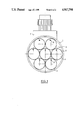
- FIG. 1 is a plan view of one embodiment of a tube plate in accordance with the invention.
- FIG. 2 is a side view in partial section of a separator device in accordance with the invention.
- FIG. 1 is a plan view of a tube plate in accordance with an embodiment of the invention, and the invention is naturally not limited to this particular embodiment as shown.
- the assembly constituted by the fibers and the tube plate(s) is mounted in a generally cylindrical envelope into which the fluid to be treated is inserted either to pass from the outside towards the inside of the fibers so as to escape in purified form beyond the outlet tube plate, or else so that it passes from the inside towards the outside of the fibers leaving in purified form between the inlet tube plate and the other end which may be constituted by another tube plate, or otherwise.
- the envelope 1 contains a tube plate 2 constituted by a resin, e.g. an epoxy resin, which sticks together hollow fiber ends 3.
- the tube plate of the present invention contains a plurality of elementary bundles 4 of fibers 3 (with only a few fibers being shown in order to avoid overcrowding the figure) with the elementary bundles being distinct from one another and being separated by reinforcing elements 5 which surround each of them.
- the right cross-section of the reinforcing elements 5 is circular, and there are seven of them, thereby enabling them to be disposed in a relatively compact configuration.
- Other cross-sections could naturally be envisaged, for example they could be polygonal and in particular hexagonal or octagonal in order to facilitate obtaining a relatively compact configuration.
- the reinforcing elements 5 which are described below as being circular in section for reasons for convenience, are constituted by tube sleeves which surround the ends of the bundles of fibers and are made in the form of grids, gratings, or lattices of a material which is sufficiently rigid in order to obtain the desired strength (e.g. metal or plastic materials).
- a material which is sufficiently rigid in order to obtain the desired strength (e.g. metal or plastic materials).
- FIG. 2 is shown diagrammatically in FIG. 2.
- This form comprises a cylinder which is regularly perforated by close-together holes 6 of arbitrary shape, e.g. circular.
- the open space ratio, the shape, the distribution, the number, and the size of the mesh are all determined as a function of the desired flow rate and flow distribution.
- the spacing between the mesh holes is designed to ensure that the sleeve remains strong enough.
- Such sleeves constitute a very simple means for avoiding any deformation of the tube plate under the effect of pressure differences between the two faces of the plate.
- the sleeves embedded in the outlet tube plate extend beyond said plate over the entire length of the elementary bundles as far as their second ends which are stuck together to form a second tube plate.
- FIG. 2 shows in which an envelope 1 contains a plurality of sleeves or reinforcing elements 5 which are perforated by holes 6 surrounding a plurality of elementary bundles of fibers 3 each of which is terminated at each end in a tube plate.
- the two tube plates interconnected in this way by the reinforcing elements are better able to withstand the compression or traction forces to which they are subjected due to the pressure difference which exists between the inside and the outside of the envelope.
- such a disposition facilitates installing the hollow fibers in the envelope and facilitates the flow of fluid at the outside of the fibers with the fluid merely having to find a tortuous path between the fibers after which it can flow freely in the spaced between the sleeves 5, thereby considerably reducing head losses.
- the envelope 1 is connected to a network for the fluid to be treated either via its ends, or else via an inlet duct 8 and/or an outlet duct 7. Whichever disposition is used, the presence of sleeves subdividing the set of hollow fibers gives rise to better fluid distribution since free passages are available between the sleeves. In addition, the fact of having an assembly of several bundles means that empty spaces are left at the inside periphery of the envelope which means that fluid inlets/outlets can be put into place by a suitable choice of diameters for the sleeves and for the envelope such that fluid flow is facilitated and excessive head loss avoided. Further, baffles 9 may be provided level with said inlets and/or outlets in order to provide local protection of the bundle from the hydraulic forces generated by the restrictions of these inlets and/or outlets.
- a baffle 9 is provided level with the inlet duct 8
- a baffle 10 is provided level with the outlet duct 7 essentially for the purpose of protecting the bundle.
- the device shown in FIG. 2 may have the following characteristics:
- the perforated sleeves may also be used to support a prefilter (as in a multiple tube filter), thereby performing prefiltering.
- the separator device may be constituted by a plurality of bundles of hollow fibers attached to a rigid riser (rod or bar) which is fixed to the two sleeves on each elementary bundle and which holds them apart.
- the bundle is kept on the riser e.g. by a tape or cloth which is wound spirally thereabout in order to individualize each bundle.
- a plurality of hanks of hollow fibers are prepared which are small in diameter compared with the hanks normally used so as to subdivide the set of hollow fibers into a plurality of elementary bundles, after which a perforated sleeve is fitted over at least one of the ends of each hank, and the sleeves are disposed in the desired configuration in order to enable them to be stuck together with an appropriate resin.
- Sticking may be done, for example, by potting the ends of the bundles in a mold or by applying resin by centrifuging. Each bundle end may be stuck individually to its sleeve, essentially for testing prior to final assembly, and then all of the bundles and sleeves may be assembled by a second gluing operation. It is also possible to mount the sleeves removably in the tube plate in order to enable them to be dismantled, e.g. for maintenance purposes.
- perforated sleeves in the tube plate makes it possible to secure the sleeves firmly in the resin since the resins passes through the perforations and ensures intimate bonding.
- subdividing the fibers into a plurality of bundles also makes it easier for the resin to penetrate during gluing.
Landscapes
- Chemical & Material Sciences (AREA)
- Chemical Kinetics & Catalysis (AREA)
- Engineering & Computer Science (AREA)
- Manufacturing & Machinery (AREA)
- Separation Using Semi-Permeable Membranes (AREA)
- Spinning Methods And Devices For Manufacturing Artificial Fibers (AREA)
- Cell Separators (AREA)
- Artificial Filaments (AREA)
Applications Claiming Priority (2)
| Application Number | Priority Date | Filing Date | Title |
|---|---|---|---|
| FR8804067A FR2629361B1 (fr) | 1988-03-29 | 1988-03-29 | Procede de fabrication d'une plaque tubulaire pour appareil de separation a fibres creuses, et dispositifs obtenus |
| FR8804067 | 1988-03-29 |
Publications (1)
| Publication Number | Publication Date |
|---|---|
| US4917798A true US4917798A (en) | 1990-04-17 |
Family
ID=9364717
Family Applications (1)
| Application Number | Title | Priority Date | Filing Date |
|---|---|---|---|
| US07/326,533 Expired - Lifetime US4917798A (en) | 1988-03-29 | 1989-03-21 | Method of fabricating a perforated plate for a hollow fiber separator apparatus, and devices obtained thereby |
Country Status (7)
| Country | Link |
|---|---|
| US (1) | US4917798A (de) |
| EP (1) | EP0335760B1 (de) |
| AT (1) | ATE56375T1 (de) |
| DE (1) | DE68900008D1 (de) |
| DK (1) | DK148589A (de) |
| ES (1) | ES2018364B3 (de) |
| FR (1) | FR2629361B1 (de) |
Cited By (15)
| Publication number | Priority date | Publication date | Assignee | Title |
|---|---|---|---|---|
| EP0811474A2 (de) * | 1996-02-15 | 1997-12-10 | JOHNSON & JOHNSON VISION PRODUCTS, INC. | Vorrichtung und Verfahren zur Entgassung entionisierten Wassers für Inspektion und Verpackung |
| WO2003000389A2 (en) * | 2001-06-22 | 2003-01-03 | Petro Sep International Ltd. | Membrane-assisted fluid separation apparatus and method |
| US6635179B1 (en) * | 1999-12-30 | 2003-10-21 | Nephros, Inc. | Sterile fluid filtration cartridge and method for using same |
| WO2005030374A1 (en) * | 2003-09-26 | 2005-04-07 | Koch Membrane Systems, Inc. | Reinforced filtration cartridge and method of making same |
| US20070163943A1 (en) * | 2005-09-02 | 2007-07-19 | Nephros, Inc. | Dual stage ultrafilter devices in the form of portable filter devices, shower devices, and hydration packs |
| US20090078625A1 (en) * | 2005-11-03 | 2009-03-26 | Palumbo Giuseppe | Redundant ultrafiltration device |
| US20090115078A1 (en) * | 2005-06-20 | 2009-05-07 | Carl Freudenberg Kg | Hollow Fiber System |
| JP2015182056A (ja) * | 2014-03-26 | 2015-10-22 | 日東電工株式会社 | 中空糸膜モジュール |
| US20160151744A1 (en) * | 2013-06-12 | 2016-06-02 | Evonik Fibres Gmbh | Membrane cartridge system |
| EP2883592A4 (de) * | 2012-08-10 | 2016-09-21 | Ube Industries | Gastrennmembranmodul |
| US20180282292A1 (en) * | 2004-12-22 | 2018-10-04 | Chemtor, LP. | Method And System For Production Of A Chemical Commodity Using A Fiber Conduit Reactor |
| US10213745B2 (en) | 2011-12-22 | 2019-02-26 | Refine Technology, Llc | Hollow fiber cartridges and components and methods of their construction |
| WO2019141498A1 (en) * | 2018-01-16 | 2019-07-25 | Nanostone Water Inc. | Membrane modules with limited defects and related methods |
| US10526299B2 (en) | 2004-12-22 | 2020-01-07 | Chemtor, Lp | Fiber conduit reactor with a heat exchange medium inlet and a heat exchange medium outlet |
| US10946309B2 (en) * | 2018-11-29 | 2021-03-16 | Merichem Company | Liquid-liquid mass transfer process and apparatus |
Families Citing this family (3)
| Publication number | Priority date | Publication date | Assignee | Title |
|---|---|---|---|---|
| FR2639248B1 (fr) * | 1988-11-21 | 1990-12-28 | Lyonnaise Eaux | Carter pour modules de filtration a faisceaux de fibres |
| EP0585614A3 (de) * | 1992-08-03 | 1994-03-23 | L'air Liquide, Societe Anonyme Pour L'etude Et L'exploitation Des Procedes Georges Claude | Hohlfasern-Permeationsvorrichtung mit Vorform für Rohrplatte |
| US5282964A (en) * | 1993-02-19 | 1994-02-01 | The Dow Chemical Company | Boreside feed hollow fiber membrane device |
Citations (4)
| Publication number | Priority date | Publication date | Assignee | Title |
|---|---|---|---|---|
| US3228877A (en) * | 1960-09-19 | 1966-01-11 | Dow Chemical Co | Permeability separatory apparatus and process utilizing hollow fibers |
| US3616928A (en) * | 1969-10-02 | 1971-11-02 | Du Pont | Permeation separation device for separating fluids |
| US4308654A (en) * | 1979-09-24 | 1982-01-05 | Monsanto Company | Methods for assembling permeators |
| US4430219A (en) * | 1978-01-10 | 1984-02-07 | Tayo Boseki Kabushiki Karsha | Hollow fiber package body and its production |
Family Cites Families (5)
| Publication number | Priority date | Publication date | Assignee | Title |
|---|---|---|---|---|
| FR1471991A (fr) * | 1966-02-21 | 1967-03-03 | Du Pont | Procédé et appareil pour séparer des fluides |
| DD129043A1 (de) * | 1976-11-30 | 1977-12-28 | Christian Jonas | Permeator mit tubulaeren membranbuendeln |
| JPS5492580A (en) * | 1977-12-29 | 1979-07-21 | Nippon Zeon Co Ltd | Hollow fiber type material transferring apparatus |
| JPS621409A (ja) * | 1985-06-26 | 1987-01-07 | Kurita Water Ind Ltd | 中空糸による濾過モジユ−ル |
| JPS62163709A (ja) * | 1986-01-14 | 1987-07-20 | Hitachi Ltd | 濾過塔 |
-
1988
- 1988-03-29 FR FR8804067A patent/FR2629361B1/fr not_active Expired - Lifetime
-
1989
- 1989-03-03 DE DE8989400599T patent/DE68900008D1/de not_active Expired - Lifetime
- 1989-03-03 AT AT89400599T patent/ATE56375T1/de active
- 1989-03-03 ES ES89400599T patent/ES2018364B3/es not_active Expired - Lifetime
- 1989-03-03 EP EP89400599A patent/EP0335760B1/de not_active Expired - Lifetime
- 1989-03-21 US US07/326,533 patent/US4917798A/en not_active Expired - Lifetime
- 1989-03-28 DK DK148589A patent/DK148589A/da not_active IP Right Cessation
Patent Citations (4)
| Publication number | Priority date | Publication date | Assignee | Title |
|---|---|---|---|---|
| US3228877A (en) * | 1960-09-19 | 1966-01-11 | Dow Chemical Co | Permeability separatory apparatus and process utilizing hollow fibers |
| US3616928A (en) * | 1969-10-02 | 1971-11-02 | Du Pont | Permeation separation device for separating fluids |
| US4430219A (en) * | 1978-01-10 | 1984-02-07 | Tayo Boseki Kabushiki Karsha | Hollow fiber package body and its production |
| US4308654A (en) * | 1979-09-24 | 1982-01-05 | Monsanto Company | Methods for assembling permeators |
Cited By (27)
| Publication number | Priority date | Publication date | Assignee | Title |
|---|---|---|---|---|
| EP0811474A3 (de) * | 1996-02-15 | 2000-07-19 | JOHNSON & JOHNSON VISION PRODUCTS, INC. | Vorrichtung und Verfahren zur Entgassung entionisierten Wassers für Inspektion und Verpackung |
| EP0811474A2 (de) * | 1996-02-15 | 1997-12-10 | JOHNSON & JOHNSON VISION PRODUCTS, INC. | Vorrichtung und Verfahren zur Entgassung entionisierten Wassers für Inspektion und Verpackung |
| US6635179B1 (en) * | 1999-12-30 | 2003-10-21 | Nephros, Inc. | Sterile fluid filtration cartridge and method for using same |
| US7459084B2 (en) * | 2001-06-22 | 2008-12-02 | Petro Sep International Ltd. | Membrane-assisted fluid separation apparatus and method |
| WO2003000389A3 (en) * | 2001-06-22 | 2003-05-30 | Petro Sep Internat Ltd | Membrane-assisted fluid separation apparatus and method |
| US20040211726A1 (en) * | 2001-06-22 | 2004-10-28 | Baig Fakhir U. | Membrane-assisted fluid separation apparatus and method |
| WO2003000389A2 (en) * | 2001-06-22 | 2003-01-03 | Petro Sep International Ltd. | Membrane-assisted fluid separation apparatus and method |
| WO2005030374A1 (en) * | 2003-09-26 | 2005-04-07 | Koch Membrane Systems, Inc. | Reinforced filtration cartridge and method of making same |
| US20050121391A1 (en) * | 2003-09-26 | 2005-06-09 | Koch David H. | Reinforced filtration cartridge and method of making same |
| US10526299B2 (en) | 2004-12-22 | 2020-01-07 | Chemtor, Lp | Fiber conduit reactor with a heat exchange medium inlet and a heat exchange medium outlet |
| US10189806B2 (en) | 2004-12-22 | 2019-01-29 | Chemtor, LP. | Fiber conduit apparatus for conducting chemical reactions and chemical extractions |
| US20180282292A1 (en) * | 2004-12-22 | 2018-10-04 | Chemtor, LP. | Method And System For Production Of A Chemical Commodity Using A Fiber Conduit Reactor |
| US8104748B2 (en) | 2005-06-20 | 2012-01-31 | Carl Freudenberg Kg | Hollow fiber system |
| US20090115078A1 (en) * | 2005-06-20 | 2009-05-07 | Carl Freudenberg Kg | Hollow Fiber System |
| US7534349B2 (en) | 2005-09-02 | 2009-05-19 | Nephros, Inc. | Dual stage ultrafilter devices in the form of portable filter devices, shower devices, and hydration packs |
| US8343347B2 (en) | 2005-09-02 | 2013-01-01 | Nephros, Inc. | Dual stage ultrafilter devices in the form of portable filter devices, shower devices, and hydration packs |
| US20070163943A1 (en) * | 2005-09-02 | 2007-07-19 | Nephros, Inc. | Dual stage ultrafilter devices in the form of portable filter devices, shower devices, and hydration packs |
| US7775375B2 (en) | 2005-11-03 | 2010-08-17 | Medica S.R.L. | Redundant ultrafiltration device |
| US20090078625A1 (en) * | 2005-11-03 | 2009-03-26 | Palumbo Giuseppe | Redundant ultrafiltration device |
| US10213745B2 (en) | 2011-12-22 | 2019-02-26 | Refine Technology, Llc | Hollow fiber cartridges and components and methods of their construction |
| EP2883592A4 (de) * | 2012-08-10 | 2016-09-21 | Ube Industries | Gastrennmembranmodul |
| US9504962B2 (en) | 2012-08-10 | 2016-11-29 | Ube Industries, Ltd. | Gas-separating membrane module |
| US20160151744A1 (en) * | 2013-06-12 | 2016-06-02 | Evonik Fibres Gmbh | Membrane cartridge system |
| US10456750B2 (en) * | 2013-06-12 | 2019-10-29 | Evonik Fibres Gmbh | Membrane cartridge system |
| JP2015182056A (ja) * | 2014-03-26 | 2015-10-22 | 日東電工株式会社 | 中空糸膜モジュール |
| WO2019141498A1 (en) * | 2018-01-16 | 2019-07-25 | Nanostone Water Inc. | Membrane modules with limited defects and related methods |
| US10946309B2 (en) * | 2018-11-29 | 2021-03-16 | Merichem Company | Liquid-liquid mass transfer process and apparatus |
Also Published As
| Publication number | Publication date |
|---|---|
| FR2629361B1 (fr) | 1991-10-25 |
| EP0335760A1 (de) | 1989-10-04 |
| ES2018364B3 (es) | 1991-04-01 |
| FR2629361A1 (fr) | 1989-10-06 |
| DK148589A (da) | 1989-09-30 |
| DK148589D0 (da) | 1989-03-28 |
| DE68900008D1 (de) | 1990-10-18 |
| EP0335760B1 (de) | 1990-09-12 |
| ATE56375T1 (de) | 1990-09-15 |
Similar Documents
| Publication | Publication Date | Title |
|---|---|---|
| US4917798A (en) | Method of fabricating a perforated plate for a hollow fiber separator apparatus, and devices obtained thereby | |
| US4031012A (en) | Separatory apparatus | |
| US4352736A (en) | Wound flattened hollow fiber assembly having plural spaced core sections | |
| US5264171A (en) | Method of making spiral-wound hollow fiber membrane fabric cartridges and modules having flow-directing baffles | |
| US3884814A (en) | Apparatus for fractionating fluids | |
| US4080296A (en) | Hollow fiber permeator | |
| US4207192A (en) | Hollow filament separatory module and method of fabrication | |
| US5160673A (en) | Hollow fiber module | |
| KR100519690B1 (ko) | 개선된 미공성 막 여과 조립체 | |
| EP0540877A2 (de) | Zweiseitig endendes Hohlfaserbündel und Trennungsvorrichtung für Fluide | |
| EP0038611B1 (de) | Hohlfasermoduln und Verfahren zu deren Herstellung | |
| EP0234893B1 (de) | Rohrplatte für Permeationsvorrichtung mit spiralförmig gewickelten Hohlfasern | |
| US4341005A (en) | Manufacture of hollow fiber fluid fractionating cells | |
| JPS61167407A (ja) | 中空糸濾過膜モジユ−ルの製造方法 | |
| US4210536A (en) | Hollow filament separatory module | |
| EP0177510A1 (de) | System zum wickeln eines bündels. | |
| EP0226431B1 (de) | Hohlfasermodul für Trennungsverfahren | |
| CA2299016A1 (en) | Sheet of filtration, separation or reaction elements, a module comprising such a sheet, and methods for producing the sheet and module | |
| US4578190A (en) | Fluid distribution system for separation modules | |
| US5183566A (en) | Hollow fiber module built up from concentric cylinders of hollow fibers | |
| US4220489A (en) | Method of fabricating a hollow filament separator module | |
| US4565630A (en) | Fluid distribution system for separation modules | |
| EP0585614A2 (de) | Hohlfasern-Permeationsvorrichtung mit Vorform für Rohrplatte | |
| JPH04219126A (ja) | 中空糸ステープル及び中空糸パッケージの製法、及び流体からのガスの分離法並びに濾過法 | |
| US20050126982A1 (en) | Membrane module having fiber breakage protection |
Legal Events
| Date | Code | Title | Description |
|---|---|---|---|
| AS | Assignment |
Owner name: LYONNAISE DES EAUX, FRANCE Free format text: ASSIGNMENT OF ASSIGNORS INTEREST.;ASSIGNORS:LIOU, JUN K.;APTEL, PHILIPPE;REEL/FRAME:005081/0269 Effective date: 19890310 |
|
| STCF | Information on status: patent grant |
Free format text: PATENTED CASE |
|
| FPAY | Fee payment |
Year of fee payment: 4 |
|
| FPAY | Fee payment |
Year of fee payment: 8 |
|
| FPAY | Fee payment |
Year of fee payment: 12 |