US4913485A - Truck sleeper cab - Google Patents
Truck sleeper cab Download PDFInfo
- Publication number
- US4913485A US4913485A US07/069,837 US6983787A US4913485A US 4913485 A US4913485 A US 4913485A US 6983787 A US6983787 A US 6983787A US 4913485 A US4913485 A US 4913485A
- Authority
- US
- United States
- Prior art keywords
- cab
- truck
- side wall
- portions
- wall
- Prior art date
- Legal status (The legal status is an assumption and is not a legal conclusion. Google has not performed a legal analysis and makes no representation as to the accuracy of the status listed.)
- Expired - Lifetime
Links
Images


Classifications
-
- B—PERFORMING OPERATIONS; TRANSPORTING
- B62—LAND VEHICLES FOR TRAVELLING OTHERWISE THAN ON RAILS
- B62D—MOTOR VEHICLES; TRAILERS
- B62D33/00—Superstructures for load-carrying vehicles
- B62D33/06—Drivers' cabs
- B62D33/0612—Cabins with living accommodation, especially for long distance road vehicles, i.e. sleeping, cooking, or other facilities
Definitions
- truck-tractor-trailer rigs used for long distance hauling of goods have sometimes been provided with sleeping compartments for the drivers.
- the sleeping compartments have been provided in the rear of and as part of the truck cab itself. In other instances, the sleeping compartment has been provided in a separate sleeping cab unit mounted on the truck frame behind the truck cab.
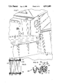
- FIG. 3 is a side elevational view of the sleeping cab unit as mounted on a truck;
Abstract
Description
Claims (28)
Priority Applications (3)
| Application Number | Priority Date | Filing Date | Title |
|---|---|---|---|
| US07/069,837 US4913485A (en) | 1987-07-06 | 1987-07-06 | Truck sleeper cab |
| CA000569420A CA1308142C (en) | 1987-07-06 | 1988-06-14 | Truck sleeper cab |
| US07/502,873 US5083834A (en) | 1987-07-06 | 1990-03-30 | Truck sleeper cab |
Applications Claiming Priority (1)
| Application Number | Priority Date | Filing Date | Title |
|---|---|---|---|
| US07/069,837 US4913485A (en) | 1987-07-06 | 1987-07-06 | Truck sleeper cab |
Related Child Applications (1)
| Application Number | Title | Priority Date | Filing Date |
|---|---|---|---|
| US07/502,873 Continuation US5083834A (en) | 1987-07-06 | 1990-03-30 | Truck sleeper cab |
Publications (1)
| Publication Number | Publication Date |
|---|---|
| US4913485A true US4913485A (en) | 1990-04-03 |
Family
ID=22091512
Family Applications (1)
| Application Number | Title | Priority Date | Filing Date |
|---|---|---|---|
| US07/069,837 Expired - Lifetime US4913485A (en) | 1987-07-06 | 1987-07-06 | Truck sleeper cab |
Country Status (2)
| Country | Link |
|---|---|
| US (1) | US4913485A (en) |
| CA (1) | CA1308142C (en) |
Cited By (21)
| Publication number | Priority date | Publication date | Assignee | Title |
|---|---|---|---|---|
| US5386674A (en) * | 1992-09-17 | 1995-02-07 | Joseph T. Ryerson & Son, Inc. | Two piece bulkhead door for rail cars and the like |
| US5556498A (en) * | 1994-12-19 | 1996-09-17 | Roamer Corporation | Method of manufacturing a recreational vehicle cabin |
| US5560673A (en) * | 1994-02-04 | 1996-10-01 | Paccar Inc. | Truck cab and sleeper assembly |
| US5928735A (en) * | 1995-06-07 | 1999-07-27 | Havco Wood Products, Inc. | Composite wood flooring |
| US6213531B1 (en) | 1999-12-08 | 2001-04-10 | Paccar Inc | Extendable sleeper for a truck |
| US6276748B1 (en) | 1998-03-17 | 2001-08-21 | Western Sear Trucks Inc. | Lightweight cab/sleeper for trucks |
| US6276736B1 (en) | 2000-09-01 | 2001-08-21 | Paccar Inc. | Storage compartment for a vehicle |
| US6464288B2 (en) * | 2001-01-25 | 2002-10-15 | Mack Trucks, Inc. | Modular truck sleeper assembly |
| US6558765B2 (en) | 1995-06-07 | 2003-05-06 | Havco Wood Products L.L.C. | Method of manufacturing composite wood flooring |
| US20050266200A1 (en) * | 2003-09-04 | 2005-12-01 | Havco Wood Products Llc | Trailer flooring with hotmelt coating |
| US20060179733A1 (en) * | 2005-02-11 | 2006-08-17 | Havco Wood Products, L.L.C. | Durable wood-plastic composite flooring for trailers |
| US20070193179A1 (en) * | 2006-01-27 | 2007-08-23 | Prolam, Societe En Commandite | Wooden laminated floor product to improve strength, water protection and fatigue resistance |
| US7263754B1 (en) * | 2005-10-12 | 2007-09-04 | Henry David J | Truck sleeper |
| US20080236704A1 (en) * | 2006-10-02 | 2008-10-02 | Prolam, Societe En Commandite | Utilization of coloration to improve the detection of "hit or miss" defects when using scanner equipment and an automated saw to remove defects in wood pieces |
| US20100295334A1 (en) * | 2008-02-01 | 2010-11-25 | Rockland Flooring | Reinforced wood flooring with a discontinuous glue pattern for truck trailers and containers |
| US20120067511A1 (en) * | 2010-09-20 | 2012-03-22 | Composite Solutions, Inc. | Method for manufacturing composite components |
| US20130062910A1 (en) * | 2011-09-11 | 2013-03-14 | Valtra Oy Ab | Tractor Cabs |
| US8857125B2 (en) | 2012-06-27 | 2014-10-14 | Industrial Hardwood Products, Inc. | Wood flooring with sealed joints for truck trailers and containers |
| US9434421B1 (en) | 2015-06-02 | 2016-09-06 | Rockland Flooring Llc | Wood flooring with reinforced thermoplastic underlayer |
| US10112351B2 (en) | 2012-10-30 | 2018-10-30 | Composite Solutions, Inc. | Method for manufacturing slide-room for recreational vehicle |
| US10974664B2 (en) | 2019-03-25 | 2021-04-13 | Flare Space, Llc | Vehicle retrofit providing extended interior width |
Citations (17)
| Publication number | Priority date | Publication date | Assignee | Title |
|---|---|---|---|---|
| US2728702A (en) * | 1951-07-13 | 1955-12-27 | Lockheed Aircraft Corp | Composite cellular plastic structure |
| US2730772A (en) * | 1953-06-22 | 1956-01-17 | Gustaf P Jones | Trailer wall construction |
| US3163434A (en) * | 1961-03-14 | 1964-12-29 | Dairy Equipment Co | Truck tank |
| US3586119A (en) * | 1968-07-11 | 1971-06-22 | George D Greer | Power train and trailer |
| US3625560A (en) * | 1969-12-15 | 1971-12-07 | Robert M Bjork | Boot for camper-truck combination |
| DE2127862A1 (en) * | 1971-06-04 | 1972-08-31 | VIATEST Baumaschinen und Fahr zeugwerk Ernst Otto Heise, 7251 Flacht | Portable laboratory house |
| DE2128042A1 (en) * | 1971-06-05 | 1972-12-14 | Dechentreiter, Josef, 8857 Wertingen | Caravan |
| US3817545A (en) * | 1972-09-08 | 1974-06-18 | B Ward | Vehicle |
| US3879240A (en) * | 1973-08-17 | 1975-04-22 | Raymond W Wall | Method of making a unitary camper structure |
| US4121684A (en) * | 1977-02-17 | 1978-10-24 | Paccar Inc. | Truck with tilting cab and non-tilting separated sleeping compartment |
| US4157201A (en) * | 1977-09-02 | 1979-06-05 | Leer, Inc. | Pick-up truck camper door assembly |
| US4201415A (en) * | 1978-03-22 | 1980-05-06 | Jaroslav Suchanek | Long-distance truck tractor with living quarters |
| JPS57107925A (en) * | 1980-12-24 | 1982-07-05 | Ikeda Bussan Co Ltd | Connecting method and device of carpet for vehicle |
| US4378856A (en) * | 1981-02-24 | 1983-04-05 | Double Eagle Industries, Inc. | Passageway for truck cab and sleeper unit |
| US4491362A (en) * | 1981-09-23 | 1985-01-01 | Kennedy Thomas H | Automotive fiberglass body |
| US4542933A (en) * | 1981-02-06 | 1985-09-24 | Rainer Bischoff | Camper superstructure |
| FR2572106A1 (en) * | 1984-10-19 | 1986-04-25 | Lantermoz Entreprise Henri | Method for constructing gables for very tall structures and the means for implementing the method |
-
1987
- 1987-07-06 US US07/069,837 patent/US4913485A/en not_active Expired - Lifetime
-
1988
- 1988-06-14 CA CA000569420A patent/CA1308142C/en not_active Expired
Patent Citations (17)
| Publication number | Priority date | Publication date | Assignee | Title |
|---|---|---|---|---|
| US2728702A (en) * | 1951-07-13 | 1955-12-27 | Lockheed Aircraft Corp | Composite cellular plastic structure |
| US2730772A (en) * | 1953-06-22 | 1956-01-17 | Gustaf P Jones | Trailer wall construction |
| US3163434A (en) * | 1961-03-14 | 1964-12-29 | Dairy Equipment Co | Truck tank |
| US3586119A (en) * | 1968-07-11 | 1971-06-22 | George D Greer | Power train and trailer |
| US3625560A (en) * | 1969-12-15 | 1971-12-07 | Robert M Bjork | Boot for camper-truck combination |
| DE2127862A1 (en) * | 1971-06-04 | 1972-08-31 | VIATEST Baumaschinen und Fahr zeugwerk Ernst Otto Heise, 7251 Flacht | Portable laboratory house |
| DE2128042A1 (en) * | 1971-06-05 | 1972-12-14 | Dechentreiter, Josef, 8857 Wertingen | Caravan |
| US3817545A (en) * | 1972-09-08 | 1974-06-18 | B Ward | Vehicle |
| US3879240A (en) * | 1973-08-17 | 1975-04-22 | Raymond W Wall | Method of making a unitary camper structure |
| US4121684A (en) * | 1977-02-17 | 1978-10-24 | Paccar Inc. | Truck with tilting cab and non-tilting separated sleeping compartment |
| US4157201A (en) * | 1977-09-02 | 1979-06-05 | Leer, Inc. | Pick-up truck camper door assembly |
| US4201415A (en) * | 1978-03-22 | 1980-05-06 | Jaroslav Suchanek | Long-distance truck tractor with living quarters |
| JPS57107925A (en) * | 1980-12-24 | 1982-07-05 | Ikeda Bussan Co Ltd | Connecting method and device of carpet for vehicle |
| US4542933A (en) * | 1981-02-06 | 1985-09-24 | Rainer Bischoff | Camper superstructure |
| US4378856A (en) * | 1981-02-24 | 1983-04-05 | Double Eagle Industries, Inc. | Passageway for truck cab and sleeper unit |
| US4491362A (en) * | 1981-09-23 | 1985-01-01 | Kennedy Thomas H | Automotive fiberglass body |
| FR2572106A1 (en) * | 1984-10-19 | 1986-04-25 | Lantermoz Entreprise Henri | Method for constructing gables for very tall structures and the means for implementing the method |
Cited By (34)
| Publication number | Priority date | Publication date | Assignee | Title |
|---|---|---|---|---|
| US5386674A (en) * | 1992-09-17 | 1995-02-07 | Joseph T. Ryerson & Son, Inc. | Two piece bulkhead door for rail cars and the like |
| US5560673A (en) * | 1994-02-04 | 1996-10-01 | Paccar Inc. | Truck cab and sleeper assembly |
| US5556498A (en) * | 1994-12-19 | 1996-09-17 | Roamer Corporation | Method of manufacturing a recreational vehicle cabin |
| US6558765B2 (en) | 1995-06-07 | 2003-05-06 | Havco Wood Products L.L.C. | Method of manufacturing composite wood flooring |
| US5928735A (en) * | 1995-06-07 | 1999-07-27 | Havco Wood Products, Inc. | Composite wood flooring |
| US6558766B2 (en) | 1995-06-07 | 2003-05-06 | Havco Wood Products L.L.C. | Composite wood flooring |
| US6276748B1 (en) | 1998-03-17 | 2001-08-21 | Western Sear Trucks Inc. | Lightweight cab/sleeper for trucks |
| US6213531B1 (en) | 1999-12-08 | 2001-04-10 | Paccar Inc | Extendable sleeper for a truck |
| US6276736B1 (en) | 2000-09-01 | 2001-08-21 | Paccar Inc. | Storage compartment for a vehicle |
| US6464288B2 (en) * | 2001-01-25 | 2002-10-15 | Mack Trucks, Inc. | Modular truck sleeper assembly |
| US20050266200A1 (en) * | 2003-09-04 | 2005-12-01 | Havco Wood Products Llc | Trailer flooring with hotmelt coating |
| US8337994B2 (en) | 2003-09-04 | 2012-12-25 | Havco Wood Products, Llc | Trailer flooring with hotmelt coating |
| US20110223328A1 (en) * | 2003-09-04 | 2011-09-15 | Havco Wood Products, LLC. | Trailer flooring with hotmelt coating |
| US7972707B2 (en) | 2003-09-04 | 2011-07-05 | Havco Wood Products, LLC. | Trailer flooring with hotmelt coating |
| US20060179733A1 (en) * | 2005-02-11 | 2006-08-17 | Havco Wood Products, L.L.C. | Durable wood-plastic composite flooring for trailers |
| US7263754B1 (en) * | 2005-10-12 | 2007-09-04 | Henry David J | Truck sleeper |
| US20070193179A1 (en) * | 2006-01-27 | 2007-08-23 | Prolam, Societe En Commandite | Wooden laminated floor product to improve strength, water protection and fatigue resistance |
| US7926524B2 (en) | 2006-10-02 | 2011-04-19 | Prolam, Societe En Commandite | Utilization of coloration to improve the detection of “hit or miss” defects when using scanner equipment and an automated saw to remove defects in wood pieces |
| US20080236704A1 (en) * | 2006-10-02 | 2008-10-02 | Prolam, Societe En Commandite | Utilization of coloration to improve the detection of "hit or miss" defects when using scanner equipment and an automated saw to remove defects in wood pieces |
| US20100295334A1 (en) * | 2008-02-01 | 2010-11-25 | Rockland Flooring | Reinforced wood flooring with a discontinuous glue pattern for truck trailers and containers |
| US20120067511A1 (en) * | 2010-09-20 | 2012-03-22 | Composite Solutions, Inc. | Method for manufacturing composite components |
| US20120068491A1 (en) * | 2010-09-20 | 2012-03-22 | Composite Solutions, Inc. | Slide-room for recreational vehicle |
| US8454072B2 (en) * | 2010-09-20 | 2013-06-04 | Composite Solutions, Inc. | Slide-room for recreational vehicle |
| US8603289B2 (en) * | 2010-09-20 | 2013-12-10 | Composite Solutions Inc. | Method for manufacturing composite components |
| US8702143B2 (en) | 2010-09-20 | 2014-04-22 | Composite Solutions, Inc. | Slide-room for recreational vehicle |
| US20130062910A1 (en) * | 2011-09-11 | 2013-03-14 | Valtra Oy Ab | Tractor Cabs |
| US8857125B2 (en) | 2012-06-27 | 2014-10-14 | Industrial Hardwood Products, Inc. | Wood flooring with sealed joints for truck trailers and containers |
| US10112351B2 (en) | 2012-10-30 | 2018-10-30 | Composite Solutions, Inc. | Method for manufacturing slide-room for recreational vehicle |
| US9434421B1 (en) | 2015-06-02 | 2016-09-06 | Rockland Flooring Llc | Wood flooring with reinforced thermoplastic underlayer |
| US9878744B2 (en) | 2015-06-02 | 2018-01-30 | Rockland Flooring Llc | Wood flooring with reinforced thermoplastic underlayer |
| US10464616B2 (en) | 2015-06-02 | 2019-11-05 | Rockland Flooring Llc | Wood flooring with reinforced thermoplastic underlayer |
| US11046370B2 (en) | 2015-06-02 | 2021-06-29 | Rockland Flooring Llc | Wood flooring with reinforced thermoplastic underlayer |
| US10974664B2 (en) | 2019-03-25 | 2021-04-13 | Flare Space, Llc | Vehicle retrofit providing extended interior width |
| US11318894B2 (en) | 2019-03-25 | 2022-05-03 | Flarespace Al, Llc | Vehicle retrofit providing extended interior width |
Also Published As
| Publication number | Publication date |
|---|---|
| CA1308142C (en) | 1992-09-29 |
Similar Documents
| Publication | Publication Date | Title |
|---|---|---|
| US5083834A (en) | Truck sleeper cab | |
| US4913485A (en) | Truck sleeper cab | |
| US5066067A (en) | Prefabricated bus housing | |
| US6640500B1 (en) | Modular door in which a window lift forms the structural frame for the trim panel | |
| US6540285B2 (en) | Motorhome with increased interior ceiling height | |
| US8047467B2 (en) | Integrated closet system | |
| US20020066184A1 (en) | Method of fabricating a motorhome | |
| US4745643A (en) | Modular sleeping unit for ship crew or the like | |
| US4145080A (en) | Meat rail support system | |
| US20100117394A1 (en) | Floor module including seating | |
| JP3675630B2 (en) | Railway vehicle | |
| US2883233A (en) | Method of making molded shell trailer bodies | |
| US4791768A (en) | Composite structure for mobile carriages and method of construction thereof | |
| EP1104374B9 (en) | A structural element arranged to form at least a part of a shell of a car body of a railway vehicle | |
| US7588283B2 (en) | Truck bed cover | |
| US4295678A (en) | Van modifiers | |
| GB2241516A (en) | Insulated panels and assemblies | |
| US4569554A (en) | Van body structure | |
| US5556498A (en) | Method of manufacturing a recreational vehicle cabin | |
| US6782623B1 (en) | Body mouting system | |
| GB2044187A (en) | Improvements in and relating to insulated compartments | |
| RU19795U1 (en) | MOBILE BUILDING | |
| JP3734490B2 (en) | Shoulder interior panel for railway vehicles | |
| US2882836A (en) | Interior lining and baggage rack for vehicles such as railway cars and the like | |
| JP4234699B2 (en) | Ceiling interior panel for railway vehicles |
Legal Events
| Date | Code | Title | Description |
|---|---|---|---|
| STCF | Information on status: patent grant |
Free format text: PATENTED CASE |
|
| AS | Assignment |
Owner name: MOFFATT, EUGENE V., PENNSYLVANIA Free format text: ASSIGNMENT OF ASSIGNORS INTEREST.;ASSIGNORS:MOFFATT, EUGENE V.;MOFFATT, RAYMOND H.;JONES, VIVIAN S.;AND OTHERS;REEL/FRAME:006240/0434 Effective date: 19920709 Owner name: MOFFATT, ROBERT H., PENNSYLVANIA Free format text: ASSIGNMENT OF ASSIGNORS INTEREST.;ASSIGNORS:MOFFATT, EUGENE V.;MOFFATT, RAYMOND H.;JONES, VIVIAN S.;AND OTHERS;REEL/FRAME:006240/0434 Effective date: 19920709 Owner name: MOFFATT, RAYMOND H., PENNSYLVANIA Free format text: ASSIGNMENT OF ASSIGNORS INTEREST.;ASSIGNORS:MOFFATT, EUGENE V.;MOFFATT, RAYMOND H.;JONES, VIVIAN S.;AND OTHERS;REEL/FRAME:006240/0434 Effective date: 19920709 |
|
| FPAY | Fee payment |
Year of fee payment: 4 |
|
| FPAY | Fee payment |
Year of fee payment: 8 |
|
| REMI | Maintenance fee reminder mailed | ||
| FPAY | Fee payment |
Year of fee payment: 12 |
|
| SULP | Surcharge for late payment |
Year of fee payment: 11 |