US4909461A - Stubout bar - Google Patents
Stubout bar Download PDFInfo
- Publication number
- US4909461A US4909461A US07/200,409 US20040988A US4909461A US 4909461 A US4909461 A US 4909461A US 20040988 A US20040988 A US 20040988A US 4909461 A US4909461 A US 4909461A
- Authority
- US
- United States
- Prior art keywords
- bar
- notch
- stubout
- pipe
- flange
- Prior art date
- Legal status (The legal status is an assumption and is not a legal conclusion. Google has not performed a legal analysis and makes no representation as to the accuracy of the status listed.)
- Expired - Fee Related
Links
Images

Classifications
-
- E—FIXED CONSTRUCTIONS
- E03—WATER SUPPLY; SEWERAGE
- E03C—DOMESTIC PLUMBING INSTALLATIONS FOR FRESH WATER OR WASTE WATER; SINKS
- E03C1/00—Domestic plumbing installations for fresh water or waste water; Sinks
- E03C1/02—Plumbing installations for fresh water
- E03C1/021—Devices for positioning or connecting of water supply lines
-
- F—MECHANICAL ENGINEERING; LIGHTING; HEATING; WEAPONS; BLASTING
- F16—ENGINEERING ELEMENTS AND UNITS; GENERAL MEASURES FOR PRODUCING AND MAINTAINING EFFECTIVE FUNCTIONING OF MACHINES OR INSTALLATIONS; THERMAL INSULATION IN GENERAL
- F16L—PIPES; JOINTS OR FITTINGS FOR PIPES; SUPPORTS FOR PIPES, CABLES OR PROTECTIVE TUBING; MEANS FOR THERMAL INSULATION IN GENERAL
- F16L3/00—Supports for pipes, cables or protective tubing, e.g. hangers, holders, clamps, cleats, clips, brackets
- F16L3/22—Supports for pipes, cables or protective tubing, e.g. hangers, holders, clamps, cleats, clips, brackets specially adapted for supporting a number of parallel pipes at intervals
- F16L3/223—Supports for pipes, cables or protective tubing, e.g. hangers, holders, clamps, cleats, clips, brackets specially adapted for supporting a number of parallel pipes at intervals each support having one transverse base for supporting the pipes
-
- E—FIXED CONSTRUCTIONS
- E03—WATER SUPPLY; SEWERAGE
- E03C—DOMESTIC PLUMBING INSTALLATIONS FOR FRESH WATER OR WASTE WATER; SINKS
- E03C1/00—Domestic plumbing installations for fresh water or waste water; Sinks
- E03C1/02—Plumbing installations for fresh water
- E03C2001/028—Alignment aids for plumbing installations
Definitions
- the present invention relates to the field of home construction generally and plumbing specifically.
- Stubout bars are used to support pipes that carry water into a bathroom or kitchen or some other area of the house where water is needed. During construction of the house the bars are attaended to studs in the wall of the house.
- the present invention uses notches instead of holes in the metal bar or strip. This allows the pipes to be easily snapped into place and held firmly without having to be soldered. Therefore, either plastic or metal pipes may be used. Also, metal pipes may still be soldered if that is what is desired.
- the inventor knows of no prior art which uses notches instead of holes. See, for example, U.S. Pat. No. 4,550,451 (Hubbard).
- the present invention is a stubout bar.
- the bar uses notches instead of holes to support the pipes as they are brought into the house.
- the notches maintain the required distance between the pipes as do the holes, however, the notches provide an easy method by which the pipes may be put into place.
- the pipes may be snapped into the notches and are held securely by the unique design of the notch.
- the notch is designed to have an arcuate shape.
- the base of the notch is formed by a flange that comprises an arc of more than 180°. This arc, by means of its unique and simple design, pinches the pipe as it is snapped into place and firmly holds the pipe in place.
- the flange provides an excellent surface for soldering the pipe to the stubout bar should additional support for the pipe be required.
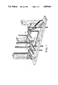
- FIG. 1 is a perspective view of the metal bar.
- FIG. 2 is a side view showing one of the brackets shown in FIG. 1.
- FIG. 3 is an end view of one of the brackets shown in FIG. 1.
- FIG. 4 is a side view on one of the brackets shown in FIG. 1.
- FIG. 5 is an end view of the bracket shown in FIG. 4.
- FIG. 6 is an end view of the bracket shown in FIG. 2.
- the invention comprises a rectangular metal bar 10 and a series of notches 13.
- the notches 13 are spaced as required by plumbing fixtures and are cut into long side 14 of the rectangularly shaped metal bar 10.
- FIG. 4 shows the notch 40, a notch edge 30, and a flange 20.
- the flange 20 forms the base of the notch 40.
- the flange 20 is part of the notch 40 and forms a partial rig of slightly more than 180° in arc. Desirably it interferes just slightly with placing a standard sized pipe in the notch, but not enough to prevent the metal from yielding resiliently when the pipe is forced into place. Interference of 0.003 inch to 0.005 inch is correct for standard thickness stubout bars.
- the notch edge 30 is that portion of the notch 40 that is not covered by the flange 20.
- the notch edge 30 is located at the top of the notch 40 where the long side 14 of the metal bar 10 borders the space created by the notch 40
- the combination of the notch edge 30, the notch 40, and the flange 20 forms the device of the invention whereby a pipe may be snapped into the notch 40 and held firmly in place by the flange 20.
- the flange 20 provides a surface 21 which would allow the pipe to be soldered to the metal bar 10 if so desired.
- FIG. 2 illustrates the metal bar 10. Specifically, FIG. 2 shows the location of the locating tabs 12 and the nail or rivet holes 11.
- FIG. 3 which is a view from line 3--3 of FIG. 2, show the orientation of the locating tabs 12 with respect to the metal bar 10.
- the locating tabs 12 may be hammered into the studs and permanently fasten the stubout bar 10 to the studs. If further support is needed or it is not desired to hammer the locating tabs 12 into the wall studs, nails or rivets may be driven through the nail or rivet holes 11 of the stubout bar 10 and the bar 10 may be attached by that method; whereby the placement of the pipes in the notches 13 may begin.
Abstract
A stubout bar having notches instead of holes for holding plastic or metal pipes.
Description
The present invention relates to the field of home construction generally and plumbing specifically. Stubout bars are used to support pipes that carry water into a bathroom or kitchen or some other area of the house where water is needed. During construction of the house the bars are attaended to studs in the wall of the house.
Traditionally these bars have had holes cut in them and the pipes have been placed in these holes and soldered to the bars. This allowed the pipes to b brought in at a uniform height and maintained the required distances between each pipe as plumbing codes require. However, it does not allow the pipes that are to be soldered to be made out of any material other than metal.
The present invention uses notches instead of holes in the metal bar or strip. This allows the pipes to be easily snapped into place and held firmly without having to be soldered. Therefore, either plastic or metal pipes may be used. Also, metal pipes may still be soldered if that is what is desired. The inventor knows of no prior art which uses notches instead of holes. See, for example, U.S. Pat. No. 4,550,451 (Hubbard).
The present invention is a stubout bar. The bar uses notches instead of holes to support the pipes as they are brought into the house. The notches maintain the required distance between the pipes as do the holes, however, the notches provide an easy method by which the pipes may be put into place. The pipes may be snapped into the notches and are held securely by the unique design of the notch. The notch is designed to have an arcuate shape. The base of the notch is formed by a flange that comprises an arc of more than 180°. This arc, by means of its unique and simple design, pinches the pipe as it is snapped into place and firmly holds the pipe in place. Furthermore, when the pipe is metal the flange provides an excellent surface for soldering the pipe to the stubout bar should additional support for the pipe be required.
These and other benefits of the present invention will be apparent to one skilled in the art from the following description.
FIG. 1 is a perspective view of the metal bar.
FIG. 2 is a side view showing one of the brackets shown in FIG. 1.
FIG. 3 is an end view of one of the brackets shown in FIG. 1.
FIG. 4 is a side view on one of the brackets shown in FIG. 1.
FIG. 5 is an end view of the bracket shown in FIG. 4.
FIG. 6 is an end view of the bracket shown in FIG. 2.
Although the disclosure hereof is detailed and exact to enable those skilled in the art to practice the invention, the physical embodiments herein disclosed merely exemplify the invention which may be embodied in other specific structure. While the preferred embodiment has been described, the details may be changed without departing from the invention, which is defined by the claims.
As shown in FIG. 2, the invention comprises a rectangular metal bar 10 and a series of notches 13. The notches 13 are spaced as required by plumbing fixtures and are cut into long side 14 of the rectangularly shaped metal bar 10.
FIG. 4, shows the notch 40, a notch edge 30, and a flange 20. The flange 20 forms the base of the notch 40. The flange 20 is part of the notch 40 and forms a partial rig of slightly more than 180° in arc. Desirably it interferes just slightly with placing a standard sized pipe in the notch, but not enough to prevent the metal from yielding resiliently when the pipe is forced into place. Interference of 0.003 inch to 0.005 inch is correct for standard thickness stubout bars. The notch edge 30 is that portion of the notch 40 that is not covered by the flange 20. The notch edge 30 is located at the top of the notch 40 where the long side 14 of the metal bar 10 borders the space created by the notch 40 The combination of the notch edge 30, the notch 40, and the flange 20 forms the device of the invention whereby a pipe may be snapped into the notch 40 and held firmly in place by the flange 20. Furthermore, as illustrated in FIG. 5, the flange 20 provides a surface 21 which would allow the pipe to be soldered to the metal bar 10 if so desired.
FIG. 2 illustrates the metal bar 10. Specifically, FIG. 2 shows the location of the locating tabs 12 and the nail or rivet holes 11. FIG. 3 which is a view from line 3--3 of FIG. 2, show the orientation of the locating tabs 12 with respect to the metal bar 10. Once proper location for the metal bar has been determined, the locating tabs 12 may be hammered into the studs and permanently fasten the stubout bar 10 to the studs. If further support is needed or it is not desired to hammer the locating tabs 12 into the wall studs, nails or rivets may be driven through the nail or rivet holes 11 of the stubout bar 10 and the bar 10 may be attached by that method; whereby the placement of the pipes in the notches 13 may begin.
The foregoing is considered as illustrative only of the principles of the invention. Furthermore, since numerous modifications and changes will readily occur to those skilled in the art, it is not desired to limit the invention to the exact construction and operation shown and described.
Claims (1)
1. A stubout bar comprising:
a solderable metal bar sized to extend between two supports in a building wall;
openings in said bar located and sized to receive fasteners securing said bar to said supports;
a plurality of notches extending in a linear series along the metal bar;
each said notch being arcuate in shape, the base of each said notch being a continuous flange which extends through an arc of slightly greater then 180°, said flange forming a segment of a circle of sufficient arcuate extent whereby a pipe may be snapped into the notch, the flange holding the pipe in place and providing a surface which may be easily soldered.
Priority Applications (1)
| Application Number | Priority Date | Filing Date | Title |
|---|---|---|---|
| US07/200,409 US4909461A (en) | 1988-05-31 | 1988-05-31 | Stubout bar |
Applications Claiming Priority (1)
| Application Number | Priority Date | Filing Date | Title |
|---|---|---|---|
| US07/200,409 US4909461A (en) | 1988-05-31 | 1988-05-31 | Stubout bar |
Publications (1)
| Publication Number | Publication Date |
|---|---|
| US4909461A true US4909461A (en) | 1990-03-20 |
Family
ID=22741608
Family Applications (1)
| Application Number | Title | Priority Date | Filing Date |
|---|---|---|---|
| US07/200,409 Expired - Fee Related US4909461A (en) | 1988-05-31 | 1988-05-31 | Stubout bar |
Country Status (1)
| Country | Link |
|---|---|
| US (1) | US4909461A (en) |
Cited By (23)
| Publication number | Priority date | Publication date | Assignee | Title |
|---|---|---|---|---|
| US5050824A (en) * | 1990-05-02 | 1991-09-24 | George R. Hubbard | Secure support pipe fastener |
| US5060892A (en) * | 1990-09-24 | 1991-10-29 | Glen Dougherty | Plumbing hanger bracket assembly |
| US5418986A (en) * | 1992-07-20 | 1995-05-30 | Geberit Ag | Attachment plate for mounting for example sanitary fixture |
| US5593115A (en) * | 1994-06-15 | 1997-01-14 | Lewis; James M. | Pipe hanger |
| US5833179A (en) * | 1996-04-16 | 1998-11-10 | Vandenberg; Lester J. | Pipe bracket |
| US6012685A (en) * | 1993-08-31 | 2000-01-11 | Saraceno, Jr.; Eugene A. | Electrical wire positioning |
| WO2000063502A1 (en) * | 1999-04-21 | 2000-10-26 | Stahl- Und Maschinenbau Graf Gmbh | Plumbing element for sanitary objects |
| US6375129B2 (en) * | 2000-03-06 | 2002-04-23 | Eads Deutschland Gmbh | Cable holder for attaching cables in a vehicle |
| US6375128B1 (en) | 2000-04-28 | 2002-04-23 | Securus, Inc. | Pipe locator and support |
| US6390420B1 (en) | 1999-01-08 | 2002-05-21 | James E. Rooney | Electrician's clip and method of using |
| US6796335B1 (en) * | 2000-06-09 | 2004-09-28 | Securus, Inc. | Pipe protector and support |
| US7039965B1 (en) | 2003-11-07 | 2006-05-09 | Sioux Chief Manufacturing Co., Inc. | Notched plumbing support bracket |
| US20060284025A1 (en) * | 2005-06-01 | 2006-12-21 | Foshay Electric Co., Inc. | Conduit spacer |
| US20070034751A1 (en) * | 2005-08-13 | 2007-02-15 | Robert Trickett | Device for mounting a pair of plumbing pipes and a method of mounting such a pair of pipes |
| US20070164171A1 (en) * | 2003-06-19 | 2007-07-19 | William Costas | Water supply pass-through apparatus |
| US7926765B1 (en) * | 2007-01-17 | 2011-04-19 | Securus, Inc. | Pipe locator and support |
| US20120261525A1 (en) * | 2011-04-18 | 2012-10-18 | Mordehay Yakir Ben Jakov | Sink outlet modular panel |
| US20150204461A1 (en) * | 2011-04-18 | 2015-07-23 | Mordehay Yakir Ben Jacov | Modular Plumbing Bracket |
| ITUB20153702A1 (en) * | 2015-09-17 | 2015-12-17 | Verum Italy S R L | HYDRAULIC UNIVERSAL CONNECTION SYSTEM. |
| US9385513B2 (en) | 2009-12-16 | 2016-07-05 | Warren Nigel Jones | Cable positioning arrangement |
| US10122157B1 (en) | 2015-05-14 | 2018-11-06 | Sticnstac, LLC | Panel wire support brackets |
| US10683949B1 (en) * | 2016-08-01 | 2020-06-16 | Carl Mock | Universal, adjustable, spliceable, bracket forming, and strapping material |
| WO2022023277A1 (en) * | 2020-07-30 | 2022-02-03 | WIMMER, Othmar | Mounting plate for wall-mounting at least two installation fittings, mounting system, and method for mounting |
Citations (6)
| Publication number | Priority date | Publication date | Assignee | Title |
|---|---|---|---|---|
| US3021103A (en) * | 1959-07-27 | 1962-02-13 | Peter J Beyerle | Plumbing assembly |
| US3104087A (en) * | 1961-03-21 | 1963-09-17 | Electrical Fittings Corp | Means for supporting electrical fixtures |
| FR1492552A (en) * | 1966-09-13 | 1967-08-18 | Anger Kunststoff | retainer for bundled pipes |
| US4407478A (en) * | 1981-03-06 | 1983-10-04 | Hodges Bonnie E | Pipe hanger |
| US4550451A (en) * | 1982-06-03 | 1985-11-05 | Hubbard George R | Universal plumbing pipe locator and support |
| US4605059A (en) * | 1983-12-21 | 1986-08-12 | Laporte Industries Limited | Heat exchanger |
-
1988
- 1988-05-31 US US07/200,409 patent/US4909461A/en not_active Expired - Fee Related
Patent Citations (6)
| Publication number | Priority date | Publication date | Assignee | Title |
|---|---|---|---|---|
| US3021103A (en) * | 1959-07-27 | 1962-02-13 | Peter J Beyerle | Plumbing assembly |
| US3104087A (en) * | 1961-03-21 | 1963-09-17 | Electrical Fittings Corp | Means for supporting electrical fixtures |
| FR1492552A (en) * | 1966-09-13 | 1967-08-18 | Anger Kunststoff | retainer for bundled pipes |
| US4407478A (en) * | 1981-03-06 | 1983-10-04 | Hodges Bonnie E | Pipe hanger |
| US4550451A (en) * | 1982-06-03 | 1985-11-05 | Hubbard George R | Universal plumbing pipe locator and support |
| US4605059A (en) * | 1983-12-21 | 1986-08-12 | Laporte Industries Limited | Heat exchanger |
Cited By (27)
| Publication number | Priority date | Publication date | Assignee | Title |
|---|---|---|---|---|
| US5050824A (en) * | 1990-05-02 | 1991-09-24 | George R. Hubbard | Secure support pipe fastener |
| US5060892A (en) * | 1990-09-24 | 1991-10-29 | Glen Dougherty | Plumbing hanger bracket assembly |
| US5418986A (en) * | 1992-07-20 | 1995-05-30 | Geberit Ag | Attachment plate for mounting for example sanitary fixture |
| US6012685A (en) * | 1993-08-31 | 2000-01-11 | Saraceno, Jr.; Eugene A. | Electrical wire positioning |
| US5593115A (en) * | 1994-06-15 | 1997-01-14 | Lewis; James M. | Pipe hanger |
| US5833179A (en) * | 1996-04-16 | 1998-11-10 | Vandenberg; Lester J. | Pipe bracket |
| US6390420B1 (en) | 1999-01-08 | 2002-05-21 | James E. Rooney | Electrician's clip and method of using |
| WO2000063502A1 (en) * | 1999-04-21 | 2000-10-26 | Stahl- Und Maschinenbau Graf Gmbh | Plumbing element for sanitary objects |
| US6375129B2 (en) * | 2000-03-06 | 2002-04-23 | Eads Deutschland Gmbh | Cable holder for attaching cables in a vehicle |
| US6375128B1 (en) | 2000-04-28 | 2002-04-23 | Securus, Inc. | Pipe locator and support |
| US6796335B1 (en) * | 2000-06-09 | 2004-09-28 | Securus, Inc. | Pipe protector and support |
| US20070164171A1 (en) * | 2003-06-19 | 2007-07-19 | William Costas | Water supply pass-through apparatus |
| US7469711B2 (en) * | 2003-06-19 | 2008-12-30 | William Costas | Water supply pass-through apparatus |
| US7039965B1 (en) | 2003-11-07 | 2006-05-09 | Sioux Chief Manufacturing Co., Inc. | Notched plumbing support bracket |
| US20060284025A1 (en) * | 2005-06-01 | 2006-12-21 | Foshay Electric Co., Inc. | Conduit spacer |
| US20070034751A1 (en) * | 2005-08-13 | 2007-02-15 | Robert Trickett | Device for mounting a pair of plumbing pipes and a method of mounting such a pair of pipes |
| US7926765B1 (en) * | 2007-01-17 | 2011-04-19 | Securus, Inc. | Pipe locator and support |
| US20110192940A1 (en) * | 2007-01-17 | 2011-08-11 | Securus, Inc. | Pipe locator and support |
| US8226051B2 (en) * | 2007-01-17 | 2012-07-24 | Securus, Inc. | Pipe locator and support |
| US9385513B2 (en) | 2009-12-16 | 2016-07-05 | Warren Nigel Jones | Cable positioning arrangement |
| US20120261525A1 (en) * | 2011-04-18 | 2012-10-18 | Mordehay Yakir Ben Jakov | Sink outlet modular panel |
| US20150204461A1 (en) * | 2011-04-18 | 2015-07-23 | Mordehay Yakir Ben Jacov | Modular Plumbing Bracket |
| US10122157B1 (en) | 2015-05-14 | 2018-11-06 | Sticnstac, LLC | Panel wire support brackets |
| ITUB20153702A1 (en) * | 2015-09-17 | 2015-12-17 | Verum Italy S R L | HYDRAULIC UNIVERSAL CONNECTION SYSTEM. |
| WO2017046823A1 (en) * | 2015-09-17 | 2017-03-23 | Verum Italy S.R.L | Universal hydraulic connection system |
| US10683949B1 (en) * | 2016-08-01 | 2020-06-16 | Carl Mock | Universal, adjustable, spliceable, bracket forming, and strapping material |
| WO2022023277A1 (en) * | 2020-07-30 | 2022-02-03 | WIMMER, Othmar | Mounting plate for wall-mounting at least two installation fittings, mounting system, and method for mounting |
Similar Documents
| Publication | Publication Date | Title |
|---|---|---|
| US4909461A (en) | Stubout bar | |
| US5370345A (en) | Solderable pipe hanging clamp | |
| US3162413A (en) | Bar hanger | |
| US4061092A (en) | Suspended shelf bracket | |
| US7191994B2 (en) | Brace assembly for ceiling fans and fixtures | |
| US6519791B2 (en) | Stub-out bar | |
| US4127975A (en) | Concealed fasteners for wall panels | |
| US8820026B2 (en) | Clip for perimeter trim | |
| US7039965B1 (en) | Notched plumbing support bracket | |
| US5833179A (en) | Pipe bracket | |
| US2843363A (en) | Tubing hanger | |
| US7523894B1 (en) | Eaves trough support bracket | |
| US4704838A (en) | Rounded corner ceiling runner system | |
| US6460820B1 (en) | Combination appliance hold-down plate | |
| US3307811A (en) | Wire tie down assembly | |
| US3189304A (en) | Gutter hanger | |
| US20070241242A1 (en) | Break-apart conduit bracket sheet | |
| US4429508A (en) | Anchoring device for metal roof | |
| US3895769A (en) | Gutter levelling device | |
| CA2522541C (en) | Guttering mounting bracket | |
| JP2005133894A (en) | Piping support | |
| KR0119657Y1 (en) | Heating pipe fixer | |
| US20070215141A1 (en) | Break-apart assembly for supporting an exhaust flue | |
| JPS6136692Y2 (en) | ||
| JPS6136690Y2 (en) |
Legal Events
| Date | Code | Title | Description |
|---|---|---|---|
| AS | Assignment |
Owner name: C & S MANUFACTURING CORPORATION, A WI. CORP. Free format text: ASSIGNMENT OF ASSIGNORS INTEREST.;ASSIGNOR:COLLINS, JOHN D.;REEL/FRAME:004939/0432 Effective date: 19880427 |
|
| FPAY | Fee payment |
Year of fee payment: 4 |
|
| FPAY | Fee payment |
Year of fee payment: 8 |
|
| REMI | Maintenance fee reminder mailed | ||
| LAPS | Lapse for failure to pay maintenance fees | ||
| STCH | Information on status: patent discontinuation |
Free format text: PATENT EXPIRED DUE TO NONPAYMENT OF MAINTENANCE FEES UNDER 37 CFR 1.362 |
|
| FP | Lapsed due to failure to pay maintenance fee |
Effective date: 20020320 |