US4904030A - Rubber crawler - Google Patents
Rubber crawler Download PDFInfo
- Publication number
- US4904030A US4904030A US07/224,044 US22404488A US4904030A US 4904030 A US4904030 A US 4904030A US 22404488 A US22404488 A US 22404488A US 4904030 A US4904030 A US 4904030A
- Authority
- US
- United States
- Prior art keywords
- belt
- crawler belt
- core
- base
- projections
- Prior art date
- Legal status (The legal status is an assumption and is not a legal conclusion. Google has not performed a legal analysis and makes no representation as to the accuracy of the status listed.)
- Expired - Lifetime
Links
Images


Classifications
-
- B—PERFORMING OPERATIONS; TRANSPORTING
- B62—LAND VEHICLES FOR TRAVELLING OTHERWISE THAN ON RAILS
- B62D—MOTOR VEHICLES; TRAILERS
- B62D55/00—Endless track vehicles
- B62D55/08—Endless track units; Parts thereof
- B62D55/18—Tracks
- B62D55/20—Tracks of articulated type, e.g. chains
- B62D55/202—Wheel engaging parts; Wheel guides on links
-
- B—PERFORMING OPERATIONS; TRANSPORTING
- B62—LAND VEHICLES FOR TRAVELLING OTHERWISE THAN ON RAILS
- B62D—MOTOR VEHICLES; TRAILERS
- B62D55/00—Endless track vehicles
- B62D55/08—Endless track units; Parts thereof
- B62D55/18—Tracks
- B62D55/24—Tracks of continuously flexible type, e.g. rubber belts
Definitions
- the present invention relates to a rubber crawler comprising an endless rubber-crawler belt which extends over a sprocket and an idler tumbler of a vehicle and has a running surface formed on its inner circmference and on which rollers between the sprocket and idler tumbler roll, and also relates to a crawler belt in which many cores are embedded at the base thereof perpendicularly to the longitudinal direction of the crawler belt.
- the vehicle of this type which uses a rubber crawler includes a sprocket 1, an idler tumbler 2, an endless rubber-crawler belt 100 which extends over the sprocket 1 and the idler tumbler 2, and a plurality of rollers 3 disposed interiorly of and in contact with the crawler belt 100 between the sprocket 1 and the idler tumbler 2 and which roll along the internal periphery of the crawler belt 100, as illustrated in FIG. 1.
- many cores 101 have the bases thereof embedded in the crawler belt 100 perpendicularly to the longitudinal direction of the crawler belt 100, and have guide projections 102 formed integrally thereon which protrude inwardly to form the inner circumference of crawler belt 100.
- a tensile reinforcing member 103 such as steel cord or the like is embedded in the crawler belt 100 in such a manner as to surround the outer circumferences of the cores 101.
- Wheels 3A of which respective pairs compose each roller 3 roll on the inner circumference portions of the crawler belt 100 that are outside the guide projections 102.
- Sprocket holes 104 for allowing the teeth of the sprocket 1 to be fitted therein are made in the crawler belt 100 between the cores 101, as illustrated in FIG. 3.
- the wheels 3A of the rollers 3, which roll along the internal periphery of the crawler belt 100 alternately on the cores 101 and on a rubber surface between the cores 101 are often subjected to severe vertical motion since the rollers 3 fall onto the rubber surface when reaching that surface.
- the rubber tends to be stripped from the core 101 at the boundary between the rubber and the core 100 thereby to permit water and sand etc., to enter into the interior of the crawler belt from that boundary to increase the failure of the rubber.
- that portion is damaged to thereby permit water and mud etc., to enter into that damaged portion 200 as illustrated in FIG. 4.
- the rubber located outside the projections 102 tends to be damaged. This can be prevented by making the rubber of the crawler belt 100 thicker, but that is not actually done.
- the rubber crawler of the present invention includes a sprocket, an idler tumbler, a plurality of rollers, an endless rubber crawler belt which extends over the sprocket and the idler tumbler of a vehicle and has a running surface formed on its inner circumference and on which the rollers between the sprocket and the idler tumbler roll, and in the crawler belt in which many cores are embedded at the bases thereof perpendicularly to the longitudinally direction of the crawler belt the core further having a surface corresponding to the surface of the crawler belt along which rollers are rolled, the surface of the core is made wider that the base of the core longitudinally of the crawler belt.
- the rubber crawler of the present invention thus provides an extended core part having a surface corresponding to the surface along which rollers are rolled, the core surface being wider longitudinally of the crawler belt than the width of the base of the core. In the rubber crawler of the invention the aforementioned problems are thereby eliminated.
- FIG. 1 is a side view illustrating a vehicle around which a prior rubber crawler is trained
- FIG. 2 is a front view in cross section illustrating the prior rubber crawler of FIG. 1;
- FIG. 3 is a plan view illustrating the prior rubber crawler of FIG. 1;
- FIG. 4 is a cross sectional view illustrating the difficulty of the prior rubber crawler
- FIG. 5 is a plan view illustrating a preferred first embodiment of a rubber crawler according to the present invention.
- FIG. 6 is a plan view illustrating a second embodiment of the rubber crawler of the present invention.
- FIG. 7 is a plan view illustrating a third embodiment of the same.
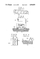
- FIG. 8 is an enlarged plan illustrating or concave portion and large-sized concave portion
- FIG. 9 is a side view in cross section of FIG. 8;
- FIG. 10 is a front view in cross section of FIG. 8;
- FIG. 11 is a perspective view illustrating a core
- FIG. 12 is a side view in cross section illustrating other embodiment of the present invention.
- FIGS. 13 and 14 are cross sections each illustrating the effect of the concave portion formed in a crawler belt according to the present invention when the crawler belt is bent;
- FIGS. 15 and 16 are plan views each illustrating another example of the core.
- FIG. 17 is a cross sectional view illustrating of core of yet another embodiment.
- FIGS. 5 to 17 embodiments of a rubber crawler according to the present invention are illustrated.
- FIG. 5 illustrates a first embodiment of a rubber crawler of the invention, in which the rubber crawler extends over a sprocket 1 and an idler tumbler 2 of a vehicle shown is FIG. 1.
- the rubber crawler includes an endless rubber crawler belt 4 having a running surface along which a plurality of rollers 3 are rolled forwardly and backwardly, and a plurality of cores 5 having bases 6 embedded in the belt, the cones 5 being mutually spaced a proper distance longitudinally of the belt.
- the core 5 includes, as best illustrated in FIGS.
- a reinforcing member 10 such as steel cords is embedded in the crawler belt 4 so as to surround the outer periphery of the cores 5 embedded in the crawler belt 4.
- wheels 3A a pair of which compose each roller 3, roll on portions of the inner circumference of the crawler belt 4 that are outside the guide projections 7, wheels 3A roll on the extended core parts 8 of the core 5, as illustrated in FIG. 10.
- FIG. 6 illustrates a second embodiment.
- a concave portion 11 is formed in the crawler belt 4 between any two adjacent cores 5 located on the passing surface on which the rollers pass.
- the depth h of the concave portion 11 is preferably greater than the thickness t of the extended core part 8.
- FIG. 7 a third embodiment is illustrated, wherein large-sized concave portions 12 and 13 are formed adjoining both ends of the concave portion 11 widthwise of the crawler belt 4 and continuously with the concave portion 11, which large-sized concave portions 12 and 13 have their lengths B and C in the longitudinal direction of the crawler shoe 4 respectively greater than the length A of the concave portion 11 (B>A, C>A), as also shown in FIG. 8.
- a numeral 14 in FIGS. 5 and 6 designates a sprocket hole.
- the large-sized concave portions 12 and 13 are not necessarily required to be two. Only one may be provided, on the side of the sprocket hole 14 (i.e., the large-sized concave portion 13).
- Such the concave portion 11 prevents, as illustrated in FIG. 13, the boundary between the core 5 and the rubber of the crawler belt 4 from being subjected to fatigue and separation when the crawler belt 4 is inwardly deflected at portions where the sprocket 1 or the idler tumbler 2 are located. Moreover, such a concave portion 11 prevents the rubber and core 5 from being separated at their boundary also when the side of the crawler belt 4 which makes contact with the ground rides up onto a stone, etc., as illustrated in FIG. 14.
- FIG. 15 illustrates another modification of the core 5 where each extended core part 8 is extended to only one side with respect to the base 6 of the core 5.
- FIG. 16 illustrates still another modification of the core 5 where the extended core parts 8 are extended oppositely.
- FIG. 17 illustrates another modification of the extended core parts 8, in which the extended core parts 8 are formed inside of a pair of guide projections 7.
Landscapes
- Engineering & Computer Science (AREA)
- Chemical & Material Sciences (AREA)
- Combustion & Propulsion (AREA)
- Transportation (AREA)
- Mechanical Engineering (AREA)
- Gears, Cams (AREA)
- Rollers For Roller Conveyors For Transfer (AREA)
Abstract
Description
Claims (4)
Applications Claiming Priority (2)
| Application Number | Priority Date | Filing Date | Title |
|---|---|---|---|
| JP62185174A JP2654620B2 (en) | 1987-07-24 | 1987-07-24 | Rubber track |
| JP62-185174 | 1987-07-24 |
Publications (1)
| Publication Number | Publication Date |
|---|---|
| US4904030A true US4904030A (en) | 1990-02-27 |
Family
ID=16166129
Family Applications (1)
| Application Number | Title | Priority Date | Filing Date |
|---|---|---|---|
| US07/224,044 Expired - Lifetime US4904030A (en) | 1987-07-24 | 1988-07-25 | Rubber crawler |
Country Status (4)
| Country | Link |
|---|---|
| US (1) | US4904030A (en) |
| EP (1) | EP0300488B1 (en) |
| JP (1) | JP2654620B2 (en) |
| DE (1) | DE3862539D1 (en) |
Cited By (30)
| Publication number | Priority date | Publication date | Assignee | Title |
|---|---|---|---|---|
| US5054873A (en) * | 1989-12-04 | 1991-10-08 | Northrop Corporation | High density integrated optical multiplexer/demultiplexer |
| US5131728A (en) * | 1988-07-13 | 1992-07-21 | Kabushiki Kaisha Komatsu Seisakusho | Crawler assembly |
| US5145242A (en) * | 1989-02-23 | 1992-09-08 | Bridgestone Corporation | Elastic endless crawler |
| US5295741A (en) * | 1991-01-30 | 1994-03-22 | Bridgestone Corporation | Core bar for rubber track and rubber track traveling device |
| US5368376A (en) * | 1991-08-26 | 1994-11-29 | Edwards, Harper, Mcnew & Company | Replacement endless vehicle tracks |
| US5482364A (en) * | 1991-08-26 | 1996-01-09 | Edwards, Harper, Mcnew & Company | Replacement endless vehicle tracks |
| US5511869A (en) * | 1991-08-26 | 1996-04-30 | Edwards, Harper, Mcnew & Company | Replacement endless vehicle tracks |
| US5522654A (en) * | 1990-10-18 | 1996-06-04 | Fukuyama Gomu Kogyo Kabushiki Gaisha | Core bar of rubber crawler and rubber crawler |
| US5536464A (en) * | 1994-11-15 | 1996-07-16 | Bridgestone/Firestone, Inc. | Apparatus and method for curing endless rubber track |
| US6290009B1 (en) * | 1996-08-20 | 2001-09-18 | Yanmar Diesel Engine Co., Ltd. | Swivel working vehicle |
| US6386654B1 (en) | 1998-12-08 | 2002-05-14 | Caterpillar Inc. | Protective cover for guide blocks |
| US6471307B2 (en) * | 2000-06-28 | 2002-10-29 | Komatsu Ltd. | Crawler belt type traveling system |
| US7416266B2 (en) | 2001-09-11 | 2008-08-26 | Soucy International Inc. | Sprocket wheel for heavy high speed multi-terrain vehicles |
| US7425044B2 (en) | 2001-09-11 | 2008-09-16 | Soucy International Inc. | Guide horn structure for endless track of high speed multi-terrain vehicles |
| US20080258550A1 (en) * | 2007-04-23 | 2008-10-23 | Mr. TIMOTHY DAVID WEBSTER | Hybrid Combination of Rubber Track with Road Wheels for a Vehicle |
| USD587728S1 (en) * | 2008-06-10 | 2009-03-03 | Bridgestone Corporation | Metallic core of rubber crawler |
| USD588168S1 (en) * | 2008-06-10 | 2009-03-10 | Bridgestone Corporation | Metallic core of rubber crawler |
| USD588167S1 (en) * | 2008-06-10 | 2009-03-10 | Bridgestone Corporation | Metallic core of rubber crawler |
| CN100551762C (en) * | 2003-11-20 | 2009-10-21 | 国立大学法人东京工业大学 | Crawler belt, crawler belt unit, and method for manufacturing crawler belt |
| US20100096914A1 (en) * | 2006-10-06 | 2010-04-22 | Breton Remi | Endless elastomeric track |
| USD617816S1 (en) * | 2009-05-26 | 2010-06-15 | Bridgestone Corporation | Metallic core of rubber crawler |
| USD618255S1 (en) * | 2009-05-26 | 2010-06-22 | Bridgestone Corporation | Metallic core of rubber crawler |
| USD823349S1 (en) | 2017-05-04 | 2018-07-17 | Caterpillar Inc. | Undercarriage track shoe for mobile earthmoving machine |
| US20200172182A1 (en) * | 2017-08-16 | 2020-06-04 | Camso Inc. | Track for traction of a vehicle |
| US10800019B2 (en) | 2017-05-04 | 2020-10-13 | Caterpillar Inc. | Track shoe geometry for a track chain |
| US10889342B2 (en) | 2017-05-04 | 2021-01-12 | Caterpillar Inc. | Contoured double pass roller path for a track chain |
| US10889343B2 (en) | 2017-05-04 | 2021-01-12 | Caterpillar Inc. | Curved track pad ribs for a track chain |
| US10894570B2 (en) | 2017-05-04 | 2021-01-19 | Caterpillar Inc. | Pin retention design for a track chain |
| US10933930B2 (en) | 2017-05-04 | 2021-03-02 | Caterpillar Inc. | Roller path of a track pad for a track chain |
| US20230058873A1 (en) * | 2021-08-18 | 2023-02-23 | Yong Jae Choi | Elastic crawler |
Families Citing this family (12)
| Publication number | Priority date | Publication date | Assignee | Title |
|---|---|---|---|---|
| JP2550685Y2 (en) * | 1989-03-18 | 1997-10-15 | 福山ゴム工業 株式会社 | Rubber track |
| JPH0335882U (en) * | 1989-08-10 | 1991-04-08 | ||
| JPH0340180U (en) * | 1989-08-11 | 1991-04-17 | ||
| JP2804104B2 (en) * | 1989-08-11 | 1998-09-24 | 横浜ゴム株式会社 | Elastic track |
| JP2527835Y2 (en) * | 1989-10-02 | 1997-03-05 | オーツタイヤ 株式会社 | Elastic crawler |
| JPH02270685A (en) * | 1990-03-28 | 1990-11-05 | Bridgestone Corp | Structure of core metal for elastic caterpillar band |
| JP2525462Y2 (en) * | 1990-04-04 | 1997-02-12 | 横浜ゴム株式会社 | Elastic track |
| DE69115669T2 (en) * | 1990-12-20 | 1996-07-18 | Bridgestone Corp | Rubber crawler |
| JP2582689B2 (en) * | 1991-08-30 | 1997-02-19 | 株式会社ブリヂストン | Crawler core |
| US5630657A (en) * | 1993-11-20 | 1997-05-20 | Bridgestone Corporation | Crawler |
| BE1012369A3 (en) | 1998-12-24 | 2000-10-03 | Tweco | Rubber chain. |
| JP4024498B2 (en) | 2001-08-06 | 2007-12-19 | 住友ゴム工業株式会社 | Rubber track core and rubber track system |
Citations (7)
| Publication number | Priority date | Publication date | Assignee | Title |
|---|---|---|---|---|
| JPS522925A (en) * | 1975-06-24 | 1977-01-11 | Ohtsu Tire & Rubber Co Ltd | Elastic crawler track |
| JPS56120462A (en) * | 1979-07-30 | 1981-09-21 | Ohtsu Tire & Rubber Co Ltd | Endless belt for endless belt device |
| JPS5932576A (en) * | 1982-08-13 | 1984-02-22 | Ohtsu Tire & Rubber Co Ltd | Resilient endless belt of crawler |
| EP0118912A2 (en) * | 1983-03-14 | 1984-09-19 | Bridgestone Corporation | Rubber crawler |
| JPS6175070A (en) * | 1984-09-17 | 1986-04-17 | Ohtsu Tire & Rubber Co Ltd | Resilient caterpillar for crawler |
| JPS61122085A (en) * | 1984-11-19 | 1986-06-10 | Bridgestone Corp | Elastic caterpillar belt |
| US4678244A (en) * | 1984-07-05 | 1987-07-07 | Bridgestone Co., Ltd. | Core of rubber crawler |
Family Cites Families (5)
| Publication number | Priority date | Publication date | Assignee | Title |
|---|---|---|---|---|
| US3027200A (en) * | 1959-11-16 | 1962-03-27 | Aircraft Armaments Inc | Tractor tracks |
| JPS567591Y2 (en) * | 1976-07-19 | 1981-02-19 | ||
| JPS57100583U (en) * | 1980-12-12 | 1982-06-21 | ||
| JPS63171291U (en) * | 1987-04-28 | 1988-11-08 | ||
| JPH0226781Y2 (en) * | 1987-06-16 | 1990-07-20 |
-
1987
- 1987-07-24 JP JP62185174A patent/JP2654620B2/en not_active Expired - Lifetime
-
1988
- 1988-07-22 DE DE8888111815T patent/DE3862539D1/en not_active Expired - Lifetime
- 1988-07-22 EP EP88111815A patent/EP0300488B1/en not_active Expired
- 1988-07-25 US US07/224,044 patent/US4904030A/en not_active Expired - Lifetime
Patent Citations (7)
| Publication number | Priority date | Publication date | Assignee | Title |
|---|---|---|---|---|
| JPS522925A (en) * | 1975-06-24 | 1977-01-11 | Ohtsu Tire & Rubber Co Ltd | Elastic crawler track |
| JPS56120462A (en) * | 1979-07-30 | 1981-09-21 | Ohtsu Tire & Rubber Co Ltd | Endless belt for endless belt device |
| JPS5932576A (en) * | 1982-08-13 | 1984-02-22 | Ohtsu Tire & Rubber Co Ltd | Resilient endless belt of crawler |
| EP0118912A2 (en) * | 1983-03-14 | 1984-09-19 | Bridgestone Corporation | Rubber crawler |
| US4678244A (en) * | 1984-07-05 | 1987-07-07 | Bridgestone Co., Ltd. | Core of rubber crawler |
| JPS6175070A (en) * | 1984-09-17 | 1986-04-17 | Ohtsu Tire & Rubber Co Ltd | Resilient caterpillar for crawler |
| JPS61122085A (en) * | 1984-11-19 | 1986-06-10 | Bridgestone Corp | Elastic caterpillar belt |
Cited By (36)
| Publication number | Priority date | Publication date | Assignee | Title |
|---|---|---|---|---|
| US5131728A (en) * | 1988-07-13 | 1992-07-21 | Kabushiki Kaisha Komatsu Seisakusho | Crawler assembly |
| US5145242A (en) * | 1989-02-23 | 1992-09-08 | Bridgestone Corporation | Elastic endless crawler |
| US5054873A (en) * | 1989-12-04 | 1991-10-08 | Northrop Corporation | High density integrated optical multiplexer/demultiplexer |
| US5522654A (en) * | 1990-10-18 | 1996-06-04 | Fukuyama Gomu Kogyo Kabushiki Gaisha | Core bar of rubber crawler and rubber crawler |
| US5295741A (en) * | 1991-01-30 | 1994-03-22 | Bridgestone Corporation | Core bar for rubber track and rubber track traveling device |
| US5511869A (en) * | 1991-08-26 | 1996-04-30 | Edwards, Harper, Mcnew & Company | Replacement endless vehicle tracks |
| US5482364A (en) * | 1991-08-26 | 1996-01-09 | Edwards, Harper, Mcnew & Company | Replacement endless vehicle tracks |
| US5368376A (en) * | 1991-08-26 | 1994-11-29 | Edwards, Harper, Mcnew & Company | Replacement endless vehicle tracks |
| US5536464A (en) * | 1994-11-15 | 1996-07-16 | Bridgestone/Firestone, Inc. | Apparatus and method for curing endless rubber track |
| US6290009B1 (en) * | 1996-08-20 | 2001-09-18 | Yanmar Diesel Engine Co., Ltd. | Swivel working vehicle |
| US6386654B1 (en) | 1998-12-08 | 2002-05-14 | Caterpillar Inc. | Protective cover for guide blocks |
| US6471307B2 (en) * | 2000-06-28 | 2002-10-29 | Komatsu Ltd. | Crawler belt type traveling system |
| US7416266B2 (en) | 2001-09-11 | 2008-08-26 | Soucy International Inc. | Sprocket wheel for heavy high speed multi-terrain vehicles |
| US7425044B2 (en) | 2001-09-11 | 2008-09-16 | Soucy International Inc. | Guide horn structure for endless track of high speed multi-terrain vehicles |
| CN100551762C (en) * | 2003-11-20 | 2009-10-21 | 国立大学法人东京工业大学 | Crawler belt, crawler belt unit, and method for manufacturing crawler belt |
| US20100096914A1 (en) * | 2006-10-06 | 2010-04-22 | Breton Remi | Endless elastomeric track |
| US8398181B2 (en) * | 2006-10-06 | 2013-03-19 | Soucy International Inc. | Endless elastomeric track |
| US20080258550A1 (en) * | 2007-04-23 | 2008-10-23 | Mr. TIMOTHY DAVID WEBSTER | Hybrid Combination of Rubber Track with Road Wheels for a Vehicle |
| USD587728S1 (en) * | 2008-06-10 | 2009-03-03 | Bridgestone Corporation | Metallic core of rubber crawler |
| USD588168S1 (en) * | 2008-06-10 | 2009-03-10 | Bridgestone Corporation | Metallic core of rubber crawler |
| USD588167S1 (en) * | 2008-06-10 | 2009-03-10 | Bridgestone Corporation | Metallic core of rubber crawler |
| USD617816S1 (en) * | 2009-05-26 | 2010-06-15 | Bridgestone Corporation | Metallic core of rubber crawler |
| USD618255S1 (en) * | 2009-05-26 | 2010-06-22 | Bridgestone Corporation | Metallic core of rubber crawler |
| USD882643S1 (en) | 2017-05-04 | 2020-04-28 | Caterpillar Inc. | Undercarriage track shoe for mobile earthmoving machine |
| USD855662S1 (en) | 2017-05-04 | 2019-08-06 | Caterpillar Inc. | Undercarriage track shoe for mobile earthmoving machine |
| USD823349S1 (en) | 2017-05-04 | 2018-07-17 | Caterpillar Inc. | Undercarriage track shoe for mobile earthmoving machine |
| US10800019B2 (en) | 2017-05-04 | 2020-10-13 | Caterpillar Inc. | Track shoe geometry for a track chain |
| US10889342B2 (en) | 2017-05-04 | 2021-01-12 | Caterpillar Inc. | Contoured double pass roller path for a track chain |
| US10889343B2 (en) | 2017-05-04 | 2021-01-12 | Caterpillar Inc. | Curved track pad ribs for a track chain |
| US10894570B2 (en) | 2017-05-04 | 2021-01-19 | Caterpillar Inc. | Pin retention design for a track chain |
| US10933930B2 (en) | 2017-05-04 | 2021-03-02 | Caterpillar Inc. | Roller path of a track pad for a track chain |
| US11702157B2 (en) | 2017-05-04 | 2023-07-18 | Caterpillar Inc. | Roller path of a track pad for a track chain |
| US11807320B2 (en) | 2017-05-04 | 2023-11-07 | Caterpillar Inc. | Pin retention design for a track chain |
| US20200172182A1 (en) * | 2017-08-16 | 2020-06-04 | Camso Inc. | Track for traction of a vehicle |
| US12110071B2 (en) * | 2017-08-16 | 2024-10-08 | Camso Inc. | Track for traction of a vehicle |
| US20230058873A1 (en) * | 2021-08-18 | 2023-02-23 | Yong Jae Choi | Elastic crawler |
Also Published As
| Publication number | Publication date |
|---|---|
| JP2654620B2 (en) | 1997-09-17 |
| DE3862539D1 (en) | 1991-05-29 |
| EP0300488A1 (en) | 1989-01-25 |
| EP0300488B1 (en) | 1991-04-24 |
| JPS6430894A (en) | 1989-02-01 |
Similar Documents
| Publication | Publication Date | Title |
|---|---|---|
| US4904030A (en) | Rubber crawler | |
| US7044567B2 (en) | Elastic endless crawler | |
| EP0428725B1 (en) | Crawler | |
| US9216784B2 (en) | Rubber crawler track | |
| JP2000001187A (en) | Driving catarpillar tread | |
| US5320585A (en) | Endless track belt assembly | |
| JP2002347675A (en) | Elastic crawler | |
| EP0304390B1 (en) | Traction device with rubber track | |
| US3515443A (en) | Traction belt | |
| JP2724871B2 (en) | Infinite elastic orbit belt | |
| JP3198119B2 (en) | Rubber Crawler Structure | |
| US5433515A (en) | Guide rollers for flexible drive belt | |
| JPS63251385A (en) | Rubber crawler | |
| JP3283630B2 (en) | Crawler belt | |
| US10435090B2 (en) | Elastic crawler | |
| JP2768511B2 (en) | Crawler traveling device | |
| JPS59106378A (en) | Rubber crawler | |
| JPH08113173A (en) | Rubber crawler | |
| JPS6322156Y2 (en) | ||
| JP2871192B2 (en) | Crawler core metal and elastic crawler | |
| JPS6230549Y2 (en) | ||
| JPS6243900B2 (en) | ||
| JP3010109B2 (en) | Elastic crawler | |
| JPH08156850A (en) | Elastic caterpillar band for crawler | |
| JPS6234867Y2 (en) |
Legal Events
| Date | Code | Title | Description |
|---|---|---|---|
| AS | Assignment |
Owner name: BRIDGESTONE CORPORATION, 10-1, KYOBASHI 1-CHOME, C Free format text: ASSIGNMENT OF ASSIGNORS INTEREST.;ASSIGNOR:ONO, YOSHIHIKO;REEL/FRAME:004927/0053 Effective date: 19880701 Owner name: BRIDGESTONE CORPORATION,JAPAN Free format text: ASSIGNMENT OF ASSIGNORS INTEREST;ASSIGNOR:ONO, YOSHIHIKO;REEL/FRAME:004927/0053 Effective date: 19880701 |
|
| STCF | Information on status: patent grant |
Free format text: PATENTED CASE |
|
| FEPP | Fee payment procedure |
Free format text: PAYOR NUMBER ASSIGNED (ORIGINAL EVENT CODE: ASPN); ENTITY STATUS OF PATENT OWNER: LARGE ENTITY |
|
| FPAY | Fee payment |
Year of fee payment: 4 |
|
| FEPP | Fee payment procedure |
Free format text: PAYER NUMBER DE-ASSIGNED (ORIGINAL EVENT CODE: RMPN); ENTITY STATUS OF PATENT OWNER: LARGE ENTITY Free format text: PAYOR NUMBER ASSIGNED (ORIGINAL EVENT CODE: ASPN); ENTITY STATUS OF PATENT OWNER: LARGE ENTITY |
|
| FPAY | Fee payment |
Year of fee payment: 8 |
|
| FPAY | Fee payment |
Year of fee payment: 12 |