US4903315A - Apparatus for enlarging or reducing an image pattern - Google Patents
Apparatus for enlarging or reducing an image pattern Download PDFInfo
- Publication number
- US4903315A US4903315A US07/355,889 US35588989A US4903315A US 4903315 A US4903315 A US 4903315A US 35588989 A US35588989 A US 35588989A US 4903315 A US4903315 A US 4903315A
- Authority
- US
- United States
- Prior art keywords
- image
- image pattern
- along
- pattern
- sensors
- Prior art date
- Legal status (The legal status is an assumption and is not a legal conclusion. Google has not performed a legal analysis and makes no representation as to the accuracy of the status listed.)
- Expired - Fee Related
Links
Images
Classifications
-
- H—ELECTRICITY
- H04—ELECTRIC COMMUNICATION TECHNIQUE
- H04N—PICTORIAL COMMUNICATION, e.g. TELEVISION
- H04N1/00—Scanning, transmission or reproduction of documents or the like, e.g. facsimile transmission; Details thereof
- H04N1/387—Composing, repositioning or otherwise geometrically modifying originals
- H04N1/393—Enlarging or reducing
-
- G—PHYSICS
- G06—COMPUTING; CALCULATING OR COUNTING
- G06V—IMAGE OR VIDEO RECOGNITION OR UNDERSTANDING
- G06V30/00—Character recognition; Recognising digital ink; Document-oriented image-based pattern recognition
- G06V30/10—Character recognition
- G06V30/16—Image preprocessing
- G06V30/166—Normalisation of pattern dimensions
-
- G—PHYSICS
- G06—COMPUTING; CALCULATING OR COUNTING
- G06V—IMAGE OR VIDEO RECOGNITION OR UNDERSTANDING
- G06V30/00—Character recognition; Recognising digital ink; Document-oriented image-based pattern recognition
- G06V30/10—Character recognition
Definitions
- the present invention relates to an apparatus for enlarging or reducing the size of an image pattern such as a character or graphic pattern and, more particularly, to an apparatus suitable for normalizing an image pattern into a pattern of a predetermined size when data representing a feature of the image pattern to be recognized is compared with a set of reference data in an image recognition apparatus.
- a conventional image recognition apparatus for recognizing an image such as a character or any other graphic pattern is designed to digitally process the image by using an electronic technique.
- An image to be recognized is processed by, e.g., vector analysis to obtain data representing a feature of the image.
- the feature data is compared with a set of reference data stored in a data base to determine by correlation calculations which reference data matches with the feature data more than the others, so that the image is specified with the most matching reference data.
- the size of the image to be recognized is indefinite. For instance, when images are characters, they vary in size whether they are printed or handwritten characters.
- a character to be recognized is read with an image sensor and converted into digital data, which is then stored in a memory.
- Feature data of the character is prepared on the basis of the digital data stored in the memory to be compared with a set of reference data, each of which is feature data prepared for each character normalized in a predetermined size.
- the feature data obtained from the character to be recognized is prepared in accordance with the size of the character while the set of the reference data to be compared with the above feature data have been derived from characters having a normalized size. Therefore, when the size of the character to be recognized is different from the normalized size, the correlation calculation often results in nonmatching even when the character to be recognized is the same as that represented by one of the set of the reference data.
- the character to be recognized must be enlarged or reduced so as to be normalized to the same size as that of the characters represented by the set of the reference data, and feature data must be derived on the basis of the normalized character to be recognized.
- the plane including a written character is scanned in proper directions, for instance, in the horizontal, vertical, 45° and 135° directions.
- the initial and last intersecting points of each scanning line with the character are detected, and thereby peripheral points of the character are found.
- the whole size and the center position of the character are then determined according to the peripheral points of the character.
- some of n ⁇ m pixels of the character stored in a memory are repeated or removed as needed on the basis of the center position of the character to normalize the character to a size constituted by n 0 33 m 0 pixels.
- an apparatus for enlarging or reducing an image pattern comprises: first and second image sensors for reading the image pattern along a predetermined scanning direction; means for relatively moving the image pattern in relation to the first and second image sensors in a direction different from the scanning direction; means for calculating the size of the image pattern along the moving direction of the image pattern on the basis of an output from the first image sensor; and means for controlling the scanning frequency of the second image sensor on the basis of the calculated size of the image pattern, the second image sensor generating an output signal having a content representing that the image pattern is enlarged or reduced along the moving direction of image pattern.
- the drawing shows a plan view and a circuit block showing an embodiment of the present invention.
- a figure "2" written on a paper 1 is exemplified as an image pattern subjected to enlargement or reduction.
- One-dimensional image sensors 3 and 4 in each of which CCDs, MOS sensors or the like are arranged in a row are spaced apart from each other by a predetermined distance over the paper 1 and are to be scanned along the Y-axis so as to read the figure "2" on the paper 1.
- the image sensors 3 and 4 are scanned along the Y-axis in response to clocks CK 1 and CK 2 of the frequencies f c1 and f c2 generated by a controller 5 including a microcomputer.
- the image sensor 3 is scanned in response to the clock CK 1 to obtain an output signal S 1 therefrom.
- the controller 5 calculates the width X 0 and the height Y 0 of the figure "2" on the basis of the signal S 1 so that the figure "2" is divided into n ⁇ m pixels according to the width X 0 and the height Y 0 obtained.
- the size of a pixel determined by the element pitch of each of the image sensors 3 and 4 is defined as ⁇ X ⁇ Y
- the values m and n are defined as follows:
- the figure "2" constituted by the n ⁇ m pixels is normalized to one having a size of n 0 ⁇ m 0 pixels.
- the normalization from n to n 0 is performed by changing the frequency f c2 of the clock CK 2 of the second image sensor 4 according to the magnitude of the value X 0 derived from the output signal S 1 of the image sensor 3 as follows:
- the frequency f c2 is changed according to the magnitude of the value X 0 , thereby obtaining an output signal S 2 representing a normalized pattern obtained by enlarging or reducing the figure "2" along the X-axis.
- the frequency f c2 is changed for the value X 0 of each of characters to be normalized.
- a character such as a figure "2" consisting of n ⁇ m pixels can be normalized to a character consisting of n 0 ⁇ m 0 pixels.
- n-to-n 0 conversion along the X-axis can be performed merely by changing the clock frequency f c2 of the image sensor 4. Therefore, the amount of data processed in a computer can be greatly reduced.
- a character written on a paper 1 is read with a pair of image sensors.
- the image on the display may be read with the image sensors.
- the pair of image sensors may be moved.
Landscapes
- Engineering & Computer Science (AREA)
- Multimedia (AREA)
- Signal Processing (AREA)
- Computer Vision & Pattern Recognition (AREA)
- Physics & Mathematics (AREA)
- General Physics & Mathematics (AREA)
- Theoretical Computer Science (AREA)
- Facsimile Scanning Arrangements (AREA)
- Editing Of Facsimile Originals (AREA)
Abstract
Disclosed is an apparatus for enlarging or reducing an image pattern, wherein the image pattern and a pair of parallel image sensors are moved relative to each other to read the image pattern, the size of the image pattern along the moving direction is calculated on the basis of an output from one image sensor, a read clock frequency of the other image sensor is controlled on the calculated size of the image pattern, and thus enlargement or reduction of the image pattern along the moving direction can be easily performed.
Description
This is a continuation of application Ser. No. 048,046, filed May 11, l987.
I. Field of the Invention
The present invention relates to an apparatus for enlarging or reducing the size of an image pattern such as a character or graphic pattern and, more particularly, to an apparatus suitable for normalizing an image pattern into a pattern of a predetermined size when data representing a feature of the image pattern to be recognized is compared with a set of reference data in an image recognition apparatus.
II. Description of the Prior Art
A conventional image recognition apparatus for recognizing an image such as a character or any other graphic pattern is designed to digitally process the image by using an electronic technique. An image to be recognized is processed by, e.g., vector analysis to obtain data representing a feature of the image. The feature data is compared with a set of reference data stored in a data base to determine by correlation calculations which reference data matches with the feature data more than the others, so that the image is specified with the most matching reference data.
In this case, however, the size of the image to be recognized is indefinite. For instance, when images are characters, they vary in size whether they are printed or handwritten characters. In a character recognition process, a character to be recognized is read with an image sensor and converted into digital data, which is then stored in a memory. Feature data of the character is prepared on the basis of the digital data stored in the memory to be compared with a set of reference data, each of which is feature data prepared for each character normalized in a predetermined size.
In this conventional process, the feature data obtained from the character to be recognized is prepared in accordance with the size of the character while the set of the reference data to be compared with the above feature data have been derived from characters having a normalized size. Therefore, when the size of the character to be recognized is different from the normalized size, the correlation calculation often results in nonmatching even when the character to be recognized is the same as that represented by one of the set of the reference data.
In order to solve this problem, the character to be recognized must be enlarged or reduced so as to be normalized to the same size as that of the characters represented by the set of the reference data, and feature data must be derived on the basis of the normalized character to be recognized.
In a conventional method for enlarging or reducing written characters, the plane including a written character is scanned in proper directions, for instance, in the horizontal, vertical, 45° and 135° directions. The initial and last intersecting points of each scanning line with the character are detected, and thereby peripheral points of the character are found. The whole size and the center position of the character are then determined according to the peripheral points of the character. Subsequently, some of n×m pixels of the character stored in a memory are repeated or removed as needed on the basis of the center position of the character to normalize the character to a size constituted by n0 33 m0 pixels.
As described above, according to the conventional method, many processing steps and long calculation time are required to enlarge or reduce one character constituted by a matrix of n×m pixels into a size of n0 ×m0 pixels. As a result, the throughout of the computer for processing is degraded.
It is an object of the present invention to provide an apparatus for enlarging or reducing an image pattern wherein the image pattern can be enlarged or reduced in the reading process so as not to require so long calculation time like a conventional apparatus, and the amount of data processed can be reduced to remarkably improve the throughput of the computer for processing.
It is another object of the present invention to provide an apparatus optimum for normalizing a character to be recognized into a size suitable for being compared with a reference pattern.
It is still another object of the present invention to provide an apparatus for enlarging or reducing an image pattern, wherein an image pattern written on a paper or displayed on a cathode-ray tube or the like can be enlarged or reduced.
The above and other objects are attained by the invention as follows.
According to the invention, an apparatus for enlarging or reducing an image pattern, comprises: first and second image sensors for reading the image pattern along a predetermined scanning direction; means for relatively moving the image pattern in relation to the first and second image sensors in a direction different from the scanning direction; means for calculating the size of the image pattern along the moving direction of the image pattern on the basis of an output from the first image sensor; and means for controlling the scanning frequency of the second image sensor on the basis of the calculated size of the image pattern, the second image sensor generating an output signal having a content representing that the image pattern is enlarged or reduced along the moving direction of image pattern.
The above and other objects and features of the invention will appear more fully hereinafter from a consideration of the following description taken in connection with accompanying drawing wherein one example is illustrated by way of example.
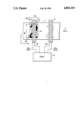
The drawing shows a plan view and a circuit block showing an embodiment of the present invention.
In an embodiment illustrated in the drawing, a figure "2" written on a paper 1 is exemplified as an image pattern subjected to enlargement or reduction.
The paper 1 on which the figure "2" having the height Y0 and the width X0 is moved at a speed v along the X-axis as indicated by an arrow 2. One-dimensional image sensors 3 and 4 in each of which CCDs, MOS sensors or the like are arranged in a row are spaced apart from each other by a predetermined distance over the paper 1 and are to be scanned along the Y-axis so as to read the figure "2" on the paper 1.
The image sensors 3 and 4 are scanned along the Y-axis in response to clocks CK1 and CK2 of the frequencies fc1 and fc2 generated by a controller 5 including a microcomputer. The frequency fc1 is given as fc1 =1/τ where τ is a time required for scanning all elements of the first image sensor 3.
The image sensor 3 is scanned in response to the clock CK1 to obtain an output signal S1 therefrom. The controller 5 calculates the width X0 and the height Y0 of the figure "2" on the basis of the signal S1 so that the figure "2" is divided into n×m pixels according to the width X0 and the height Y0 obtained. When the size of a pixel determined by the element pitch of each of the image sensors 3 and 4 is defined as ΔX×ΔY, the values m and n are defined as follows:
m=Y.sub.0 /ΔY, n=(X.sub.0 /v)×f.sub.c1
In this instance, the figure "2" constituted by the n×m pixels is normalized to one having a size of n0 ×m0 pixels.
When the normalization from m to m0 along the Y-axis is performed, the figure "2" is read at a sufficiently high scanner resolution. Therefore, read signals can be merely assigned to m0 /m times of pixels. The normalization from n to n0 is performed by changing the frequency fc2 of the clock CK2 of the second image sensor 4 according to the magnitude of the value X0 derived from the output signal S1 of the image sensor 3 as follows:
f.sub.c2 =n.sub.0 /(X.sub.0 /v)
When the figure "2" is read again by the second image sensor 4 upon movement of the paper 1, as indicated by the broken line in the drawing, after the figure "2" is read by the image sensor 3, the frequency fc2 is changed according to the magnitude of the value X0, thereby obtaining an output signal S2 representing a normalized pattern obtained by enlarging or reducing the figure "2" along the X-axis. In this case, the frequency fc2 is changed for the value X0 of each of characters to be normalized.
According to this embodiment, a character such as a figure "2" consisting of n×m pixels can be normalized to a character consisting of n0 ×m0 pixels. In this case, although m-to-m0 conversion along the Y-axis is performed by the conventional method, n-to-n0 conversion along the X-axis can be performed merely by changing the clock frequency fc2 of the image sensor 4. Therefore, the amount of data processed in a computer can be greatly reduced.
The above description has been made for normalizing a character. However, the present invention can be used for enlarging or reducing an image pattern such as a character or graphic pattern. Further, in the above embodiment, a character written on a paper 1 is read with a pair of image sensors. However, upon moving a separate character image extracted by a line and character separation preprocessing on a display such as a cathode-ray tube, the image on the display may be read with the image sensors. Of course, instead of moving the image, the pair of image sensors may be moved.
Although the invention has been described in its preferred form with a certain degree of particularity, it is understood that the present disclosure of the preferred form has been changed in the details of construction and the combination and arrangement of parts may be resorted to without departing from the spirit and the scope of the invention as hereinafter claimed.
Claims (8)
1. An apparatus for enlarging or reducing an image pattern, comprising:
substantially identical first and second image sensors for reading said image pattern with respective scanning frequencies along a predetermined scanning direction, said first and second image sensors each having sensors arranged in a row along said scanning direction;
means for relatively moving said image pattern in relation to said first and second image sensors in a direction different from said scanning direction;
means for calculating the size of said image pattern along the moving direction of said image pattern on the basis of the scanning frequency and an output of and from said first image sensor and the speed of moving said image pattern in relation to said first and second image sensors; and
means for controlling the scanning frequency of said second image sensor on the basis of the calculated size of said image pattern,
said second image sensor generating an output signal having a content representing that said image pattern is enlarged or reduced along said moving direction of said image pattern.
2. An apparatus according to claim 1, wherein each of said substantially identical first and second image sensors comprises photosensors arranged in a row along said scanning direction, said photosensors being scanned so as to read said image pattern.
3. An apparatus according to claim 1, wherein said image pattern is moved at a predetermined speed along the X-axis and said scanning direction of said substantially identical first and second image sensors is along the Y-axis.
4. An apparatus according to claim 1, wherein said image pattern is one displayed on a screen of a display unit.
5. An apparatus according to claim 1, wherein the image pattern to be read is one displayed on a screen of a display unit.
6. An apparatus for enlarging or reducing an image pattern, comprising:
means for moving the image pattern at a predetermined speed along the X-axis;
first and second image sensors for reading the image pattern with respective scanning frequencies, said first and second image sensors having substantially the same construction as each other in which photosensors are arranged in a row along the Y-axis;
means for calculating the size of the image pattern along the X axis on the basis of the scanning frequency and output signal of and from said first image sensor and the speed of moving said image pattern in relation to said first and second image sensors;
means for controlling scanning frequency of said second image sensor on the basis of the calculated size of the image pattern such that said second image sensor generates an output signal in which the image pattern is enlarged or reduced along the X-axis.
7. An apparatus for enlarging or reducing an image pattern, comprising:
substantially identical first and second image sensors for reading said image pattern with respective scanning frequencies fc1 and fc2 along a predetermined scanning direction, said first and second image sensors each having sensors arranged in a row along said scanning direction;
means for relatively moving said image pattern at a speed v in relation to said first and second image sensors in a direction different from said scanning direction;
means for calculating the size X0 of said image pattern along the moving direction of said image pattern on the basis of an output from said first image sensor and for dividing said image pattern into n pixels along the moving direction so that ##EQU1## and means for controlling the scanning frequency fc2 of said second image sensor to increase or decrease a number of said pixels along the moving direction from n to n0 pixels so that ##EQU2## said second image sensor generating an output signal having a content representing that said image pattern is enlarged or reduced along said moving direction of said image pattern.
8. A apparatus for enlarging or reducing an image pattern, comprising:
means for moving the image pattern at a predetermined speed V along the X-axis;
first and second image sensors for reading the image pattern with respective scanning frequencies fc1 and fc2, said first and second image sensors having substantially the same construction as each other in which photosensors are arranged in a row along the Y-axis;
means for calculating the size of X0 of the image pattern along the X-axis on the basis of an output signal from said first image sensor and for dividing said image pattern into n pixels along the X-axis so that ##EQU3## and means for controlling scanning frequency fc2 of said second image sensor to increase or decrease a number of said pixels along the X-axis from n to n0 pixels so that ##EQU4## such that said second image sensor generates an output signal in which the image pattern is enlarged or reduced along the X-axis.
Applications Claiming Priority (1)
| Application Number | Priority Date | Filing Date | Title |
|---|---|---|---|
| US4804687A | 1987-05-11 | 1987-05-11 |
Related Parent Applications (1)
| Application Number | Title | Priority Date | Filing Date |
|---|---|---|---|
| US4804687A Continuation | 1987-05-11 | 1987-05-11 |
Publications (1)
| Publication Number | Publication Date |
|---|---|
| US4903315A true US4903315A (en) | 1990-02-20 |
Family
ID=21952454
Family Applications (1)
| Application Number | Title | Priority Date | Filing Date |
|---|---|---|---|
| US07/355,889 Expired - Fee Related US4903315A (en) | 1987-05-11 | 1989-05-19 | Apparatus for enlarging or reducing an image pattern |
Country Status (2)
| Country | Link |
|---|---|
| US (1) | US4903315A (en) |
| JP (1) | JPS647759A (en) |
Cited By (4)
| Publication number | Priority date | Publication date | Assignee | Title |
|---|---|---|---|---|
| US5133025A (en) * | 1988-09-29 | 1992-07-21 | Sony Corporation | Scanning apparatus for reading an image |
| US5481626A (en) * | 1987-08-05 | 1996-01-02 | Canon Kabushiki Kaisha | Numerical expression reognizing apparatus |
| US5719969A (en) * | 1992-06-30 | 1998-02-17 | Canon Kabushiki Kaisha | Data input apparatus and data processing apparatus |
| US20030152270A1 (en) * | 2000-03-16 | 2003-08-14 | Hisashi Saiga | Image encoding device, decoding device and encoding method, decoding method, and recorded program on which programs of the methods are recorded |
Families Citing this family (2)
| Publication number | Priority date | Publication date | Assignee | Title |
|---|---|---|---|---|
| DE3823827A1 (en) * | 1988-07-14 | 1990-01-18 | Bosch Gmbh Robert | FUEL INJECTION DEVICE FOR INTERNAL COMBUSTION ENGINES, IN PARTICULAR PUMPEDUESE |
| IT1304976B1 (en) * | 1997-09-12 | 2001-04-05 | Honda Motor Co Ltd | ENGINE WITH CAMSHAFT IN HEAD. |
Citations (6)
| Publication number | Priority date | Publication date | Assignee | Title |
|---|---|---|---|---|
| US3179922A (en) * | 1962-04-19 | 1965-04-20 | Control Data Corp | Normalizing reading machine |
| US3189873A (en) * | 1962-08-09 | 1965-06-15 | Control Data Corp | Scanning pattern normalizer |
| US3432673A (en) * | 1967-10-06 | 1969-03-11 | Control Data Corp | Line tracking reading machine having means to positionally normalize the character-video signals |
| US3462737A (en) * | 1964-12-18 | 1969-08-19 | Ibm | Character size measuring and normalizing for character recognition systems |
| US4672681A (en) * | 1985-08-02 | 1987-06-09 | Licentia Patent-Verwaltungs Gmbh | Mail imaging method and apparatus |
| US4750048A (en) * | 1985-04-09 | 1988-06-07 | Canon Kabushiki Kaisha | Image reading device |
-
1988
- 1988-05-11 JP JP63114484A patent/JPS647759A/en active Pending
-
1989
- 1989-05-19 US US07/355,889 patent/US4903315A/en not_active Expired - Fee Related
Patent Citations (6)
| Publication number | Priority date | Publication date | Assignee | Title |
|---|---|---|---|---|
| US3179922A (en) * | 1962-04-19 | 1965-04-20 | Control Data Corp | Normalizing reading machine |
| US3189873A (en) * | 1962-08-09 | 1965-06-15 | Control Data Corp | Scanning pattern normalizer |
| US3462737A (en) * | 1964-12-18 | 1969-08-19 | Ibm | Character size measuring and normalizing for character recognition systems |
| US3432673A (en) * | 1967-10-06 | 1969-03-11 | Control Data Corp | Line tracking reading machine having means to positionally normalize the character-video signals |
| US4750048A (en) * | 1985-04-09 | 1988-06-07 | Canon Kabushiki Kaisha | Image reading device |
| US4672681A (en) * | 1985-08-02 | 1987-06-09 | Licentia Patent-Verwaltungs Gmbh | Mail imaging method and apparatus |
Cited By (4)
| Publication number | Priority date | Publication date | Assignee | Title |
|---|---|---|---|---|
| US5481626A (en) * | 1987-08-05 | 1996-01-02 | Canon Kabushiki Kaisha | Numerical expression reognizing apparatus |
| US5133025A (en) * | 1988-09-29 | 1992-07-21 | Sony Corporation | Scanning apparatus for reading an image |
| US5719969A (en) * | 1992-06-30 | 1998-02-17 | Canon Kabushiki Kaisha | Data input apparatus and data processing apparatus |
| US20030152270A1 (en) * | 2000-03-16 | 2003-08-14 | Hisashi Saiga | Image encoding device, decoding device and encoding method, decoding method, and recorded program on which programs of the methods are recorded |
Also Published As
| Publication number | Publication date |
|---|---|
| JPS647759A (en) | 1989-01-11 |
Similar Documents
| Publication | Publication Date | Title |
|---|---|---|
| US4204193A (en) | Adaptive alignment for pattern recognition system | |
| US5563403A (en) | Method and apparatus for detection of a skew angle of a document image using a regression coefficient | |
| US5075895A (en) | Method and apparatus for recognizing table area formed in binary image of document | |
| US4903315A (en) | Apparatus for enlarging or reducing an image pattern | |
| JPH07220026A (en) | Method and device for picture processing | |
| US5228095A (en) | Apparatus for recognizing printed characters | |
| EP0766193B1 (en) | Optical character reader with skew correction | |
| Lehal et al. | A range free skew detection technique for digitized Gurmukhi script documents | |
| US5361309A (en) | Character recognition apparatus and method with low-resolution storage for character extraction | |
| JP3223878B2 (en) | Character string collating device, method and recording medium | |
| CN117710985B (en) | Optical character recognition method and device and intelligent terminal | |
| JP2795860B2 (en) | Character recognition device | |
| JP2957729B2 (en) | Line direction determination device | |
| JPH07120393B2 (en) | Character recognition / graphic processing device | |
| JPH0766413B2 (en) | Document character direction detector | |
| JP2706744B2 (en) | Image data position distortion correction method | |
| JP3275475B2 (en) | Character string recognition device with known character sequence | |
| JPH0290374A (en) | Positioning device and picture processing lsi circuit | |
| JPH07225809A (en) | Automatic generation method for document read frame | |
| JPH0623983B2 (en) | Distortion correction device | |
| JPH02165288A (en) | Picture processor | |
| JP3157534B2 (en) | Table recognition method | |
| JPH04151785A (en) | Optical character reader | |
| JP2957707B2 (en) | Line direction determination device | |
| JPH05274472A (en) | Image recognizing device |
Legal Events
| Date | Code | Title | Description |
|---|---|---|---|
| FEPP | Fee payment procedure |
Free format text: PAYOR NUMBER ASSIGNED (ORIGINAL EVENT CODE: ASPN); ENTITY STATUS OF PATENT OWNER: LARGE ENTITY |
|
| REMI | Maintenance fee reminder mailed | ||
| LAPS | Lapse for failure to pay maintenance fees | ||
| FP | Lapsed due to failure to pay maintenance fee |
Effective date: 19930220 |
|
| STCH | Information on status: patent discontinuation |
Free format text: PATENT EXPIRED DUE TO NONPAYMENT OF MAINTENANCE FEES UNDER 37 CFR 1.362 |