US4901688A - Ignition plug for use in internal combustion engines and an ignition process by the use thereof - Google Patents
Ignition plug for use in internal combustion engines and an ignition process by the use thereof Download PDFInfo
- Publication number
- US4901688A US4901688A US07/313,063 US31306389A US4901688A US 4901688 A US4901688 A US 4901688A US 31306389 A US31306389 A US 31306389A US 4901688 A US4901688 A US 4901688A
- Authority
- US
- United States
- Prior art keywords
- recess
- ignition plug
- center electrode
- ground electrode
- electrode
- Prior art date
- Legal status (The legal status is an assumption and is not a legal conclusion. Google has not performed a legal analysis and makes no representation as to the accuracy of the status listed.)
- Expired - Fee Related
Links
Images

Classifications
-
- H—ELECTRICITY
- H01—ELECTRIC ELEMENTS
- H01T—SPARK GAPS; OVERVOLTAGE ARRESTERS USING SPARK GAPS; SPARKING PLUGS; CORONA DEVICES; GENERATING IONS TO BE INTRODUCED INTO NON-ENCLOSED GASES
- H01T13/00—Sparking plugs
- H01T13/46—Sparking plugs having two or more spark gaps
- H01T13/467—Sparking plugs having two or more spark gaps in parallel connection
-
- F—MECHANICAL ENGINEERING; LIGHTING; HEATING; WEAPONS; BLASTING
- F02—COMBUSTION ENGINES; HOT-GAS OR COMBUSTION-PRODUCT ENGINE PLANTS
- F02B—INTERNAL-COMBUSTION PISTON ENGINES; COMBUSTION ENGINES IN GENERAL
- F02B75/00—Other engines
- F02B75/02—Engines characterised by their cycles, e.g. six-stroke
- F02B2075/022—Engines characterised by their cycles, e.g. six-stroke having less than six strokes per cycle
- F02B2075/027—Engines characterised by their cycles, e.g. six-stroke having less than six strokes per cycle four
Definitions
- This invention relates to an ignition plug used for internal combustion engines of automobiles and the like.
- the inventors have developed an ignition plug disclosed in Japanese patent application publication No. sho 62-11471.
- a line of ignition groove is provided to on the other side of a ground electrode to a center electrode so that a small amount of gas mixture in the groove may be ignited in the first place so as to prompt combustion in the whole space of combustion chamber.
- the free end of the ground electrodes, up to which the ignition groove extends is inwardly bent so as to come close to the side surface of the center electrodes with a spark gap in between, the capacity of the ignition groove to hold gas mixture is made almost the same from one end to the other, so that the ignition power is restricted thereby and cannot be strengthened anymore.
- the free end of a ground electrode facing a center electrode is partially indented in such a way that there forms a recess for holding gas mixture, and the capacity of the recess increases with the increase of distance between the inside surface of the recess and the side surface of the center electrode.
- the ignition proceeds into the recess multiplying ignition seeds so that combustion gas instantaneously expands in the recess in an ideal condition.
- the time before combustion is greatly reduced and combustion gas is intensified so much as to ignite gas mixture in the surroundings as well.
- the ignition seeds increasingly multiply in the recess in such a stepless manner that the expansion of combustion gas follows in line with it.
- the energy loss in the ignition process can be lessened by balacing the strength of ignition and the depth of the recess.
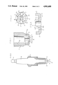
- FIG. 1 is a longitudinal cross-sectional view of an essential part of an ignition plug of this invention
- FIG. 2 is a whole elevational view of the same ignition plug as the one in FIG. 1;
- FIG. 3 is a bottom view of the same ignition plug as the one in FIG. 1;
- FIG. 4 is a partially enlarged view of an essential part of the same ignition plug as the one in FIG. 1;
- FIG. 5 is a bottom view of a variation of the ignition plug shown in FIGS. 1 through 4.
- FIG. 6 is a bottom view of another variation of the ignition plug shown in FIGS. 1 through 4;
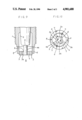
- FIG. 7 is a longitudinal cross-sectional view of an essential part of another ignition plug of this invention.
- FIG. 8 is a bottom view of the same ignition plug as the one in FIG. 7;
- FIG. 9 is a longitudinal cross-sectional view of an essential part of still another ignition plug of this invention.
- FIG. 10 is a bottom view of the same ignition plug as the one in FIG. 9;
- numeral 8 denotes a location for a pistion, but the piston itself is not shown in the above figures.
- the ignition plug Since the ignition plug has to be fixed to an engine block firmly, the outside thereof is provided with an electric conductive metal casing 1 with male thread near the top, as shown in FIG. 2.
- a pair of rectangular cross-sectioned ground electrodes 5, 5, extended portions of the metal casing are inwardly bent in the middle approximately at right angles toward the center electrode 4. Thus, a spark gap is formed between the side surface 4a of the center electrode 4 and the end 5a of the ground electrodes 5, 5.
- the area of the cross section in other words, the capacity of the notch 4 per unit length steplessly increases with the increase of distance between the inside of the notch and the side surface of the center electrode.
- the free end 5a of the ground electrodes 5, 5 is notched into such a V-shape that when high voltage is applied between the center and the ground electrodes by way of the terminal 3, there appear sparks in the spark gap 6. That is, flame seeds or primary ignition seeds are given birth to there so as to ignite gas mixture on the verge of the V-shaped notch 7 in the first place. As ignition proceeds into the notch, whose capacity steplessly increase with the increase of its distance from the center electrode 4, combustion also develops steplessly, multiplying secondary ignition seeds. In this way, the whole gas mixture in the combustion chamber is set on fire so instantaneously as to cause strong explosion.
- the following table shows the reslut of two running tests actually made on almost the same route in Osaka city by the use of an unloaded ordinary truck (1300 cc, 4 cycles, 4 cylinders), with this ignition plug or with an ordinary marketed ignition plug, provided that in both the running tests, the maximum speed was kept about 60 km/hr., and the average speed lay between 40-60 km/hr.
- FIGS. 1 through 4 show only an ignition plug with double ground electrodes; however, it is needless to say that an ignition plug with a single or triple ground electrodes is operatable as well in a similar manner if the end of those ground electrodes is shaped likewise.
- the shape of the notch 7 can be modified as shown in the bottom views of FIGS. 5 and 6, for example. That is, one is modified into a notch with flat bottom, as shown in FIG. 5, and the other is modified into a notch with circular bottom, as shown in FIG. 6. For all such modifications, one can have a desirable effect similar to that of the prototype shown in FIGS. 1 through 4.
- FIGS. 7 and 8 show another example.
- a pair of crescent ground electrodes 5, 5 are mounted on the top of stays 9, 9 extending from the metal casing 1, the stays being paralleled to the center electrodes 4.
- the end or inside surface of the ground electrodes 5, 5, which defines a spark gap 6 in association with the side surface 4a of the center electrode 4 is made so wide as to comprise a circular recess 5a in the middle, whose radius of curvature is greater than the radius of the center electrode 4, and two arched recesses 7, 7, whose function is equivalent to that of the notch 7 of the first example, on both sides thereof.
- Outside the respective arched recesses 7, 7 is a flat face 10; thus, between the flat face 10 of one ground electrode 5 and opposite flat face 10 of the other 5 is a space 11 that outwardly widens.
- the configuration of the ground electrodes and the center electrode is such that when sparks appear in the spark gap 6, they give rise to ignition seeds on the verge of the arched recesses 7, 7 where the arched recess and the circular recess meet in the first place.
- the ignition seeds increase in number, multiplying secondary ignition seeds, and cause combustion, which gas radiantly spreads out from the space 11.
- FIGS. 9 and 10 show still another example, in which a pair of ground electrodes 5, 5 in the preceeding examples are made in one so as to form a circle surrounding a center electrode 4. More spaecifically, a round ground electrode 5 is supported by a pair of stays 9, 9 extending from the metal casing 1; and in the middle of the ground electrode 5 is a substantially square hole in the center of which is located the center electrode 4 with a spark gap 6 put on each side of the hole.
- the sides of the hole comprises a circular portion 5a that forms the spark gap 6 in association with the side surface 4a of the center electrode 4, and two recesses 7, 7 on both sides of the curcular portion 5a.
- the hole has such a shape that gas mixture can be collected in plenty near every corner thereof, the function of which is thus equivalent to the notch 7 of the first example and the recess 7 of the second example. Therefore, when sparks appear in the spark gap 6, there forms a great number of ignition seeds there, and this makes a cause of strong and instantaneous combustion in the entire space of combustion chamber.
Abstract
An ignition plug of this invention is characterized in that a ground electrode thereof has a recess that faces the side surface of a single center electrode; more particularly, in the case of an L-shaped ground electrode whose free end is opposed to the center electrode with a spark gas in between, the recess is provided to on the free end of the ground electrode so that it can hold plentiful gas mixture to ignite near the spark gap by increasing its capacity with the increase of distance from the side surface of the center electrode; thus, the farther the igntion proceeds into the recess, the more intensively gas mixture is ignited, whereby instantaneous combustion can be caused in the entire space of a combustion chamber.
Description
This invention relates to an ignition plug used for internal combustion engines of automobiles and the like.
The inventors have developed an ignition plug disclosed in Japanese patent application publication No. sho 62-11471. In the ignition plug, a line of ignition groove is provided to on the other side of a ground electrode to a center electrode so that a small amount of gas mixture in the groove may be ignited in the first place so as to prompt combustion in the whole space of combustion chamber.
In the prior art, although the free end of the ground electrodes, up to which the ignition groove extends, is inwardly bent so as to come close to the side surface of the center electrodes with a spark gap in between, the capacity of the ignition groove to hold gas mixture is made almost the same from one end to the other, so that the ignition power is restricted thereby and cannot be strengthened anymore. For this reason, in an ignition plug of this invention, the free end of a ground electrode facing a center electrode is partially indented in such a way that there forms a recess for holding gas mixture, and the capacity of the recess increases with the increase of distance between the inside surface of the recess and the side surface of the center electrode.
Therefore, once gas mixture on the verge of the recess is ignited by sparks appearing in a spark gap, the ignition proceeds into the recess multiplying ignition seeds so that combustion gas instantaneously expands in the recess in an ideal condition. In consequence, not only is the ignition of gas mixture accelerated inside the recess but also secondarily forming ignition seeds can multiply much more intensively in this ignition plug than in the former one. Because of that, the time before combustion is greatly reduced and combustion gas is intensified so much as to ignite gas mixture in the surroundings as well. The ignition seeds increasingly multiply in the recess in such a stepless manner that the expansion of combustion gas follows in line with it. Thus, compared with conventional ignition plugs, the energy loss in the ignition process can be lessened by balacing the strength of ignition and the depth of the recess.
In order that this invention may be understood more clearly, reference will now be made to the structure and function of this ignition plug according to the attached drawings, in which
FIG. 1 is a longitudinal cross-sectional view of an essential part of an ignition plug of this invention;
FIG. 2 is a whole elevational view of the same ignition plug as the one in FIG. 1;
FIG. 3 is a bottom view of the same ignition plug as the one in FIG. 1;
FIG. 4 is a partially enlarged view of an essential part of the same ignition plug as the one in FIG. 1;
FIG. 5 is a bottom view of a variation of the ignition plug shown in FIGS. 1 through 4.
FIG. 6 is a bottom view of another variation of the ignition plug shown in FIGS. 1 through 4;
FIG. 7 is a longitudinal cross-sectional view of an essential part of another ignition plug of this invention.
FIG. 8 is a bottom view of the same ignition plug as the one in FIG. 7;
FIG. 9 is a longitudinal cross-sectional view of an essential part of still another ignition plug of this invention; and
FIG. 10 is a bottom view of the same ignition plug as the one in FIG. 9;
wherein numeral 8 denotes a location for a pistion, but the piston itself is not shown in the above figures.
Since the ignition plug has to be fixed to an engine block firmly, the outside thereof is provided with an electric conductive metal casing 1 with male thread near the top, as shown in FIG. 2. An insulator 2, usually made of porcelain, which covers a lead connecting a terminal 3 and a cylindrical center electrode 4, is tightly held by the metal casing 1. A pair of rectangular cross-sectioned ground electrodes 5, 5, extended portions of the metal casing are inwardly bent in the middle approximately at right angles toward the center electrode 4. Thus, a spark gap is formed between the side surface 4a of the center electrode 4 and the end 5a of the ground electrodes 5, 5.
A V-shaped notch 7, which is for holding gas mixture, is made on the end 5a of the ground electrodes 5, 5 so that the verge of the notch may span the whole breadth of the ground electrodes, as shown in the bottom view of FIG. 3. In the mean time, the area of the cross section, in other words, the capacity of the notch 4 per unit length steplessly increases with the increase of distance between the inside of the notch and the side surface of the center electrode.
The free end 5a of the ground electrodes 5, 5 is notched into such a V-shape that when high voltage is applied between the center and the ground electrodes by way of the terminal 3, there appear sparks in the spark gap 6. That is, flame seeds or primary ignition seeds are given birth to there so as to ignite gas mixture on the verge of the V-shaped notch 7 in the first place. As ignition proceeds into the notch, whose capacity steplessly increase with the increase of its distance from the center electrode 4, combustion also develops steplessly, multiplying secondary ignition seeds. In this way, the whole gas mixture in the combustion chamber is set on fire so instantaneously as to cause strong explosion.
The following table shows the reslut of two running tests actually made on almost the same route in Osaka city by the use of an unloaded ordinary truck (1300 cc, 4 cycles, 4 cylinders), with this ignition plug or with an ordinary marketed ignition plug, provided that in both the running tests, the maximum speed was kept about 60 km/hr., and the average speed lay between 40-60 km/hr.
              TABLE
______________________________________
        Consumed Covered  Fuel      Ratio of
        Fuel     mileage  efficiency
                                    efficiency
______________________________________
This plug 11.78 l    109 km   9.25 km/l
                                      130.6%
Marketed plug
          16.10 l    114 km   7.08 km/l
                                      100.0%
______________________________________
FIGS. 1 through 4 show only an ignition plug with double ground electrodes; however, it is needless to say that an ignition plug with a single or triple ground electrodes is operatable as well in a similar manner if the end of those ground electrodes is shaped likewise. Moreover, the shape of the notch 7 can be modified as shown in the bottom views of FIGS. 5 and 6, for example. That is, one is modified into a notch with flat bottom, as shown in FIG. 5, and the other is modified into a notch with circular bottom, as shown in FIG. 6. For all such modifications, one can have a desirable effect similar to that of the prototype shown in FIGS. 1 through 4.
FIGS. 7 and 8 show another example. A pair of crescent ground electrodes 5, 5 are mounted on the top of stays 9, 9 extending from the metal casing 1, the stays being paralleled to the center electrodes 4. As apparent from its bottom view shown in FIG. 8, the end or inside surface of the ground electrodes 5, 5, which defines a spark gap 6 in association with the side surface 4a of the center electrode 4, is made so wide as to comprise a circular recess 5a in the middle, whose radius of curvature is greater than the radius of the center electrode 4, and two arched recesses 7, 7, whose function is equivalent to that of the notch 7 of the first example, on both sides thereof. Outside the respective arched recesses 7, 7 is a flat face 10; thus, between the flat face 10 of one ground electrode 5 and opposite flat face 10 of the other 5 is a space 11 that outwardly widens.
The configuration of the ground electrodes and the center electrode is such that when sparks appear in the spark gap 6, they give rise to ignition seeds on the verge of the arched recesses 7, 7 where the arched recess and the circular recess meet in the first place. The ignition seeds increase in number, multiplying secondary ignition seeds, and cause combustion, which gas radiantly spreads out from the space 11.
Since the arched recesses 7, 7 on one ground electrode are opposed to the ones 7, 7 on the other respectively with the spark gap 6 in between, there forms an ample space for holding gas mixture the capacity of which steplessly increase with the increase of distance between the surface of the arched recess 7 and the side surface of the center electrode 4. Thereby greater number of ignition seeds can be given birth to there and more instantaneous combustion can result therefrom.
FIGS. 9 and 10 show still another example, in which a pair of ground electrodes 5, 5 in the preceeding examples are made in one so as to form a circle surrounding a center electrode 4. More spaecifically, a round ground electrode 5 is supported by a pair of stays 9, 9 extending from the metal casing 1; and in the middle of the ground electrode 5 is a substantially square hole in the center of which is located the center electrode 4 with a spark gap 6 put on each side of the hole. The sides of the hole comprises a circular portion 5a that forms the spark gap 6 in association with the side surface 4a of the center electrode 4, and two recesses 7, 7 on both sides of the curcular portion 5a. A recess on one side and a recess on the other next form an ample space for holding gas mixture between themselves on every corner of the hole; thus, the capacity of the space attains maximum on the diagonal where the distance between the inside surface of the ground electrode (the side of the hole) and the side surface of the center electrode 4 falls greatest.
The hole has such a shape that gas mixture can be collected in plenty near every corner thereof, the function of which is thus equivalent to the notch 7 of the first example and the recess 7 of the second example. Therefore, when sparks appear in the spark gap 6, there forms a great number of ignition seeds there, and this makes a cause of strong and instantaneous combustion in the entire space of combustion chamber.
Reference has been made to a round ground electrode with a substantially square hole to accommodate a center electrode in the middle; however, it is needless to say that the shape of the hole can be modified into triangle or pentagon in the scope of this invention, and yet one can have a desirable effect with them in a similar manner.
Claims (9)
1. An ignition plug for use in internal combustion engines, in which at least one ground electrode is paired with a center electrode, said ground electrode is inwardly bent in the middle approximately at right angles toward said center electrode so that the end thereof may face the side surface of said center electrode with a spark gap in between, and the top of said center electrode is opposed to a piston with a space in between, characterized in that the end of said ground electrode is partially indented in such a way that there may form a recess for holding gas mixture there and the capacity of said recess may steplessly increase with the increase of the distance between said recess and said center electrode.
2. An ignition plug as claimed in claim 1, in which said recess is formed into a V-shaped notch on the end of said ground electrode.
3. An ignition plug as claimed in claim 2, in which the bottom of said V-shaped notch is made flat.
4. An ignition plug as claimed in claim 2, in which the bottom of said V-shaped notch is made circular.
5. An ignition plug as claimed in claim 1, in which said ground electrode is installed in pairs on both sides of said center electrode, the end of said ground electrode, which defines said spark gap in association with the side surface of said center electrode, is made so wide as to comprise a circular recess in the middle and two arched recesses on both sides thereof, and said arched recesses on one ground electrode are opposed to the ones on the other respectively with said spark gap in between so that there forms an ample space for holding gas mixture there the capacity of which steplessly increase with the increase of distance between the surface of said arched recess and the side surface of said center electrode.
6. An ignition plug as claimed in claim 1, in which said ground electrode is formed into a round form with a substantially square hole in the middle, and supported by at least one stay extending from an electric conductive casing, said hole is made so large as to be able to accommodate said center electrode in the center thereof leaving a spark gap on each side thereof, and two recesses are provided to each side of said hole so that a recess on one side and a recess on the other next may form an ample sapce for holding gas mixture on every corner of said hole where the distance between the side of said hole and the side surface of said center electrode becomes greatest.
7. An ignition plug as claimed in claim 6, in which said hole is formed into a triangular shape.
8. An ignition plug as claimed in claim 6, in which said hole is formed into a pentagonal shape.
9. An ignition process of gas mixture in an ignition plug as claimed in any one of claims 1 through 8, comprising: igniting a smallest amount of gas mixture on the verge of said recess, nearest to said spark gap, on the end of said ground electrode by sparks formed in said spark gap in the first place, and then a larger amount of gas mixture n said recess whose capacity steplessly increases with the increase of distance between said recess and the side surface of said center electrode.
Applications Claiming Priority (2)
| Application Number | Priority Date | Filing Date | Title |
|---|---|---|---|
| JP63270176A JPH02117086A (en) | 1988-10-26 | 1988-10-26 | Ignition plug and combustion by ignition plug |
| JP63-270176 | 1988-10-26 |
Publications (1)
| Publication Number | Publication Date |
|---|---|
| US4901688A true US4901688A (en) | 1990-02-20 |
Family
ID=17482586
Family Applications (1)
| Application Number | Title | Priority Date | Filing Date |
|---|---|---|---|
| US07/313,063 Expired - Fee Related US4901688A (en) | 1988-10-26 | 1989-02-22 | Ignition plug for use in internal combustion engines and an ignition process by the use thereof |
Country Status (10)
| Country | Link |
|---|---|
| US (1) | US4901688A (en) |
| JP (1) | JPH02117086A (en) |
| CN (1) | CN1014573B (en) |
| AU (1) | AU612955B2 (en) |
| BR (1) | BR8905526A (en) |
| DE (1) | DE3934012A1 (en) |
| FR (1) | FR2640092A1 (en) |
| GB (1) | GB2224775B (en) |
| IT (1) | IT1237825B (en) |
| RU (1) | RU1838856C (en) |
Cited By (17)
| Publication number | Priority date | Publication date | Assignee | Title |
|---|---|---|---|---|
| US5090373A (en) * | 1990-11-30 | 1992-02-25 | Ryohei Kashiwara | Auxiliary device attachable to a convention spark plug |
| US5697334A (en) * | 1996-02-16 | 1997-12-16 | Alliedsignal Inc. | Spark plug with integral retainer nut |
| US5797383A (en) * | 1996-04-05 | 1998-08-25 | Ngk Spark Plug Co., Ltd. | Dual polarity type ignition system for a spark plug group |
| WO2006011950A3 (en) * | 2004-06-24 | 2006-03-02 | Woodward Governor Co | Pre-chamber spark plug |
| US20090121603A1 (en) * | 2007-11-02 | 2009-05-14 | Below Matthew B | Spark plug casing and spark plug having the spark plug casing |
| US20090309475A1 (en) * | 2005-06-07 | 2009-12-17 | Woodward Governor Company | Pre-Chamber Spark Plug |
| US20110065350A1 (en) * | 2009-09-11 | 2011-03-17 | Woodward Governor Company | Method for Forming an Electrode for a Spark Plug |
| US20130042834A9 (en) * | 2010-11-23 | 2013-02-21 | Woodward, Inc. | Controlled Spark Ignited Flame Kernel Flow in Fuel-Fed Prechambers |
| US20130206101A1 (en) * | 2012-02-09 | 2013-08-15 | Cummins Ip, Inc | Spark plug for removing residual exhaust gas and associated combustion chamber |
| US8839762B1 (en) | 2013-06-10 | 2014-09-23 | Woodward, Inc. | Multi-chamber igniter |
| US9172217B2 (en) | 2010-11-23 | 2015-10-27 | Woodward, Inc. | Pre-chamber spark plug with tubular electrode and method of manufacturing same |
| US9653886B2 (en) | 2015-03-20 | 2017-05-16 | Woodward, Inc. | Cap shielded ignition system |
| US9765682B2 (en) | 2013-06-10 | 2017-09-19 | Woodward, Inc. | Multi-chamber igniter |
| US9840963B2 (en) | 2015-03-20 | 2017-12-12 | Woodward, Inc. | Parallel prechamber ignition system |
| US9856848B2 (en) | 2013-01-08 | 2018-01-02 | Woodward, Inc. | Quiescent chamber hot gas igniter |
| US9893497B2 (en) | 2010-11-23 | 2018-02-13 | Woodward, Inc. | Controlled spark ignited flame kernel flow |
| US9890689B2 (en) | 2015-10-29 | 2018-02-13 | Woodward, Inc. | Gaseous fuel combustion |
Families Citing this family (4)
| Publication number | Priority date | Publication date | Assignee | Title |
|---|---|---|---|---|
| US5051651A (en) * | 1988-11-24 | 1991-09-24 | Tadaharu Fujiwara | Ignition plug with a hollow cylindrical ground electrode and an ignition process by the use thereof |
| WO2013019144A1 (en) * | 2011-08-04 | 2013-02-07 | Общество С Ограниченной Ответственностью "Истиные Системы" | Spark plug |
| CN104421091B (en) * | 2013-08-21 | 2017-03-01 | 张蝶儿 | A kind of ignition system of internal combustion engine and spark plug are in the installation method of combustor |
| JP6430859B2 (en) * | 2015-03-04 | 2018-11-28 | リンナイ株式会社 | Flat burner |
Citations (28)
| Publication number | Priority date | Publication date | Assignee | Title |
|---|---|---|---|---|
| US1360294A (en) * | 1920-11-30 | Spark-plttg | ||
| US1371488A (en) * | 1919-05-13 | 1921-03-15 | Martin B Jacobson | Spark-plug |
| GB187501A (en) * | 1921-12-09 | 1922-10-26 | John Edwin Temple | Improvements in or relating to sparking plugs |
| US1963801A (en) * | 1933-03-14 | 1934-06-19 | O'marra Martin | Spark plug |
| US2071572A (en) * | 1935-12-30 | 1937-02-23 | Gen Motors Corp | Radio shield for spark plugs |
| US2096199A (en) * | 1937-01-30 | 1937-10-19 | Gen Motors Corp | Spark plug |
| US2129003A (en) * | 1936-08-22 | 1938-09-06 | Grant James | Spark plug |
| US2208030A (en) * | 1939-11-06 | 1940-07-16 | Holmes Induction Deviees Inc | Spark plug |
| US2305208A (en) * | 1941-07-25 | 1942-12-15 | Irving J Mcguire | Ignition of internal combustion engines |
| US2336569A (en) * | 1941-10-13 | 1943-12-14 | Gen Motors Corp | Aircraft spark plug |
| US2368889A (en) * | 1941-10-10 | 1945-02-06 | Wright Aeronautical Corp | Shielded spark plug |
| US2372867A (en) * | 1941-12-10 | 1945-04-03 | Bendix Aviat Corp | Spark plug |
| US2391459A (en) * | 1944-05-02 | 1945-12-25 | Mallory & Co Inc P R | Spark plug and electrode therefor |
| US2616407A (en) * | 1949-10-22 | 1952-11-04 | Vernon R Thomas | Spark plug |
| US2944178A (en) * | 1956-09-21 | 1960-07-05 | Thomas S Schaub | Spark plugs |
| US3238447A (en) * | 1961-08-15 | 1966-03-01 | Gen Motors Corp | Igniter plug with spark-sensing means |
| US3313972A (en) * | 1964-10-07 | 1967-04-11 | Bosch Gmbh Robert | Spark plug with combined high tension gap and creepage spark gap |
| JPS5125743A (en) * | 1974-08-27 | 1976-03-02 | Fuji Electric Co Ltd | |
| US3970885A (en) * | 1972-09-18 | 1976-07-20 | Nippondenso Co., Ltd. | Ignition plug for internal combustion engines |
| JPS5187331A (en) * | 1975-01-30 | 1976-07-30 | Taizo Aoyama | TOBIRA |
| US4023058A (en) * | 1976-05-14 | 1977-05-10 | Jose Hector Lara | Spark plug |
| US4109633A (en) * | 1975-09-16 | 1978-08-29 | New Cosmos Electric Company Limited | Spark-plug for automobile internal combustion engine |
| US4123998A (en) * | 1976-03-15 | 1978-11-07 | Heintzelman Leo A | Flame deflector for the auxiliary combustion chamber of an internal combustion engine |
| FR2479588A1 (en) * | 1980-03-28 | 1981-10-02 | Girodin Marius | Spark plug for IC engine - has ring shaped earth electrode surrounding central electrode peg |
| US4401915A (en) * | 1977-12-28 | 1983-08-30 | Takeaki Kashiwara | Ignition plug for an internal combustion engine |
| JPS6130394A (en) * | 1984-07-24 | 1986-02-12 | 株式会社東芝 | Driving mechanism of robot joint |
| JPS6211471A (en) * | 1985-07-08 | 1987-01-20 | 越川 幸雄 | Pitching apparatus |
| US4808878A (en) * | 1985-07-03 | 1989-02-28 | Takeaki Kashiwara | Ignition plug for internal combustion engines to cause instant combustion |
Family Cites Families (10)
| Publication number | Priority date | Publication date | Assignee | Title |
|---|---|---|---|---|
| GB752675A (en) * | 1900-01-01 | |||
| FR476612A (en) * | 1914-11-25 | 1915-08-19 | Adrien Debuirre | Spark plug for internal combustion engines |
| GB160154A (en) * | 1920-03-08 | 1922-03-14 | Champion Ignition Co | Improvements in spark plugs |
| GB168024A (en) * | 1920-08-14 | 1922-03-10 | Champion Ignition Co | Improvements in spark plug electrode |
| US4015160A (en) * | 1976-01-14 | 1977-03-29 | Jose Hector Lara | Spark plug having electrodes shaped to produce a hollow spark column |
| JPS5556389A (en) * | 1978-10-20 | 1980-04-25 | Takeaki Kashiwara | Ignition plug |
| GB2032516A (en) * | 1978-10-25 | 1980-05-08 | Huang Yu Fei | Sparking plug |
| DE3407011A1 (en) * | 1984-02-27 | 1985-09-05 | Robert Bosch Gmbh, 7000 Stuttgart | Spark plug for internal-combustion engines |
| GB2210103B (en) * | 1987-09-17 | 1992-02-05 | Champion Spark Plug Europ | Spark plug for internal combustion engine |
| DD276570A1 (en) * | 1988-10-17 | 1990-02-28 | Sonnenberg Elektrokeramische | LANGLEBENSDAUERZUENDKERZE |
-
1988
- 1988-10-26 JP JP63270176A patent/JPH02117086A/en active Pending
-
1989
- 1989-02-22 US US07/313,063 patent/US4901688A/en not_active Expired - Fee Related
- 1989-10-10 AU AU42705/89A patent/AU612955B2/en not_active Ceased
- 1989-10-11 DE DE3934012A patent/DE3934012A1/en not_active Withdrawn
- 1989-10-18 FR FR8913594A patent/FR2640092A1/en not_active Withdrawn
- 1989-10-20 GB GB8923722A patent/GB2224775B/en not_active Expired - Fee Related
- 1989-10-23 CN CN89108188A patent/CN1014573B/en not_active Expired
- 1989-10-25 RU SU894742236A patent/RU1838856C/en active
- 1989-10-25 BR BR898905526A patent/BR8905526A/en unknown
- 1989-10-26 IT IT04848689A patent/IT1237825B/en active IP Right Grant
Patent Citations (28)
| Publication number | Priority date | Publication date | Assignee | Title |
|---|---|---|---|---|
| US1360294A (en) * | 1920-11-30 | Spark-plttg | ||
| US1371488A (en) * | 1919-05-13 | 1921-03-15 | Martin B Jacobson | Spark-plug |
| GB187501A (en) * | 1921-12-09 | 1922-10-26 | John Edwin Temple | Improvements in or relating to sparking plugs |
| US1963801A (en) * | 1933-03-14 | 1934-06-19 | O'marra Martin | Spark plug |
| US2071572A (en) * | 1935-12-30 | 1937-02-23 | Gen Motors Corp | Radio shield for spark plugs |
| US2129003A (en) * | 1936-08-22 | 1938-09-06 | Grant James | Spark plug |
| US2096199A (en) * | 1937-01-30 | 1937-10-19 | Gen Motors Corp | Spark plug |
| US2208030A (en) * | 1939-11-06 | 1940-07-16 | Holmes Induction Deviees Inc | Spark plug |
| US2305208A (en) * | 1941-07-25 | 1942-12-15 | Irving J Mcguire | Ignition of internal combustion engines |
| US2368889A (en) * | 1941-10-10 | 1945-02-06 | Wright Aeronautical Corp | Shielded spark plug |
| US2336569A (en) * | 1941-10-13 | 1943-12-14 | Gen Motors Corp | Aircraft spark plug |
| US2372867A (en) * | 1941-12-10 | 1945-04-03 | Bendix Aviat Corp | Spark plug |
| US2391459A (en) * | 1944-05-02 | 1945-12-25 | Mallory & Co Inc P R | Spark plug and electrode therefor |
| US2616407A (en) * | 1949-10-22 | 1952-11-04 | Vernon R Thomas | Spark plug |
| US2944178A (en) * | 1956-09-21 | 1960-07-05 | Thomas S Schaub | Spark plugs |
| US3238447A (en) * | 1961-08-15 | 1966-03-01 | Gen Motors Corp | Igniter plug with spark-sensing means |
| US3313972A (en) * | 1964-10-07 | 1967-04-11 | Bosch Gmbh Robert | Spark plug with combined high tension gap and creepage spark gap |
| US3970885A (en) * | 1972-09-18 | 1976-07-20 | Nippondenso Co., Ltd. | Ignition plug for internal combustion engines |
| JPS5125743A (en) * | 1974-08-27 | 1976-03-02 | Fuji Electric Co Ltd | |
| JPS5187331A (en) * | 1975-01-30 | 1976-07-30 | Taizo Aoyama | TOBIRA |
| US4109633A (en) * | 1975-09-16 | 1978-08-29 | New Cosmos Electric Company Limited | Spark-plug for automobile internal combustion engine |
| US4123998A (en) * | 1976-03-15 | 1978-11-07 | Heintzelman Leo A | Flame deflector for the auxiliary combustion chamber of an internal combustion engine |
| US4023058A (en) * | 1976-05-14 | 1977-05-10 | Jose Hector Lara | Spark plug |
| US4401915A (en) * | 1977-12-28 | 1983-08-30 | Takeaki Kashiwara | Ignition plug for an internal combustion engine |
| FR2479588A1 (en) * | 1980-03-28 | 1981-10-02 | Girodin Marius | Spark plug for IC engine - has ring shaped earth electrode surrounding central electrode peg |
| JPS6130394A (en) * | 1984-07-24 | 1986-02-12 | 株式会社東芝 | Driving mechanism of robot joint |
| US4808878A (en) * | 1985-07-03 | 1989-02-28 | Takeaki Kashiwara | Ignition plug for internal combustion engines to cause instant combustion |
| JPS6211471A (en) * | 1985-07-08 | 1987-01-20 | 越川 幸雄 | Pitching apparatus |
Cited By (32)
| Publication number | Priority date | Publication date | Assignee | Title |
|---|---|---|---|---|
| US5090373A (en) * | 1990-11-30 | 1992-02-25 | Ryohei Kashiwara | Auxiliary device attachable to a convention spark plug |
| US5697334A (en) * | 1996-02-16 | 1997-12-16 | Alliedsignal Inc. | Spark plug with integral retainer nut |
| US5797383A (en) * | 1996-04-05 | 1998-08-25 | Ngk Spark Plug Co., Ltd. | Dual polarity type ignition system for a spark plug group |
| WO2006011950A3 (en) * | 2004-06-24 | 2006-03-02 | Woodward Governor Co | Pre-chamber spark plug |
| US20070069617A1 (en) * | 2004-06-24 | 2007-03-29 | Tozzi Luigi P | Pre-chamber spark plug |
| US7659655B2 (en) | 2004-06-24 | 2010-02-09 | Woodward Governor Company | Pre-chamber spark plug |
| CN101006255B (en) * | 2004-06-24 | 2011-05-04 | 伍德沃德控制器公司 | Pre-chamber spark plug |
| US7922551B2 (en) | 2005-06-07 | 2011-04-12 | Woodward, Inc. | Pre-chamber spark plug |
| US20090309475A1 (en) * | 2005-06-07 | 2009-12-17 | Woodward Governor Company | Pre-Chamber Spark Plug |
| US20090121603A1 (en) * | 2007-11-02 | 2009-05-14 | Below Matthew B | Spark plug casing and spark plug having the spark plug casing |
| US8035286B2 (en) * | 2007-11-02 | 2011-10-11 | Fram Group Ip Llc | Spark plug casing and spark plug having the spark plug casing |
| US8337268B2 (en) | 2007-11-02 | 2012-12-25 | Fram Group Ip Llc | Method of making spark plug casing and spark plug having the spark plug casing |
| US20110062850A1 (en) * | 2009-09-11 | 2011-03-17 | Woodward Governor Company | Pre-Chamber Spark Plug and Electrodes Therefor |
| US20110065350A1 (en) * | 2009-09-11 | 2011-03-17 | Woodward Governor Company | Method for Forming an Electrode for a Spark Plug |
| US8461750B2 (en) | 2009-09-11 | 2013-06-11 | Woodward, Inc. | Pre-chamber spark plug and electrodes therefor |
| US8657641B2 (en) | 2009-09-11 | 2014-02-25 | Woodward Inc. | Method for forming an electrode for a spark plug |
| US20130042834A9 (en) * | 2010-11-23 | 2013-02-21 | Woodward, Inc. | Controlled Spark Ignited Flame Kernel Flow in Fuel-Fed Prechambers |
| US9893497B2 (en) | 2010-11-23 | 2018-02-13 | Woodward, Inc. | Controlled spark ignited flame kernel flow |
| US11674494B2 (en) | 2010-11-23 | 2023-06-13 | Woodward, Inc. | Pre-chamber spark plug with tubular electrode and method of manufacturing same |
| US9172217B2 (en) | 2010-11-23 | 2015-10-27 | Woodward, Inc. | Pre-chamber spark plug with tubular electrode and method of manufacturing same |
| US10907532B2 (en) | 2010-11-23 | 2021-02-02 | Woodward. Inc. | Controlled spark ignited flame kernel flow in fuel-fed prechambers |
| US9476347B2 (en) * | 2010-11-23 | 2016-10-25 | Woodward, Inc. | Controlled spark ignited flame kernel flow in fuel-fed prechambers |
| US20130206101A1 (en) * | 2012-02-09 | 2013-08-15 | Cummins Ip, Inc | Spark plug for removing residual exhaust gas and associated combustion chamber |
| US9225151B2 (en) * | 2012-02-09 | 2015-12-29 | Cummins Ip, Inc. | Spark plug for removing residual exhaust gas and associated combustion chamber |
| US9856848B2 (en) | 2013-01-08 | 2018-01-02 | Woodward, Inc. | Quiescent chamber hot gas igniter |
| US10054102B2 (en) | 2013-01-08 | 2018-08-21 | Woodward, Inc. | Quiescent chamber hot gas igniter |
| US9765682B2 (en) | 2013-06-10 | 2017-09-19 | Woodward, Inc. | Multi-chamber igniter |
| US8839762B1 (en) | 2013-06-10 | 2014-09-23 | Woodward, Inc. | Multi-chamber igniter |
| US9840963B2 (en) | 2015-03-20 | 2017-12-12 | Woodward, Inc. | Parallel prechamber ignition system |
| US9843165B2 (en) | 2015-03-20 | 2017-12-12 | Woodward, Inc. | Cap shielded ignition system |
| US9653886B2 (en) | 2015-03-20 | 2017-05-16 | Woodward, Inc. | Cap shielded ignition system |
| US9890689B2 (en) | 2015-10-29 | 2018-02-13 | Woodward, Inc. | Gaseous fuel combustion |
Also Published As
| Publication number | Publication date |
|---|---|
| GB2224775B (en) | 1993-06-02 |
| CN1042624A (en) | 1990-05-30 |
| IT8948486A0 (en) | 1989-10-26 |
| JPH02117086A (en) | 1990-05-01 |
| BR8905526A (en) | 1990-05-29 |
| AU4270589A (en) | 1990-05-03 |
| IT1237825B (en) | 1993-06-18 |
| GB2224775A (en) | 1990-05-16 |
| FR2640092A1 (en) | 1990-06-08 |
| GB8923722D0 (en) | 1989-12-06 |
| RU1838856C (en) | 1993-08-30 |
| AU612955B2 (en) | 1991-07-18 |
| DE3934012A1 (en) | 1990-05-03 |
| CN1014573B (en) | 1991-10-30 |
Similar Documents
| Publication | Publication Date | Title |
|---|---|---|
| US4901688A (en) | Ignition plug for use in internal combustion engines and an ignition process by the use thereof | |
| US5051651A (en) | Ignition plug with a hollow cylindrical ground electrode and an ignition process by the use thereof | |
| US5623179A (en) | Multi fire spark plug | |
| US4983877A (en) | Ignition plug for use in internal combustion engines to cause instantaneous combustion | |
| JPH0218883A (en) | Spark plug | |
| US4851732A (en) | Spark plug having a flame deflector for use in an internal combustion engine | |
| US6414419B1 (en) | Ignition spark plug | |
| US4808878A (en) | Ignition plug for internal combustion engines to cause instant combustion | |
| US6807933B2 (en) | Multiple sparking ignition device | |
| US5821676A (en) | Spark plug with grooved, tapered center electrode | |
| CA2088032A1 (en) | Spark plug | |
| US4470392A (en) | Multi-gap spark ignition device for engine | |
| US3725715A (en) | Spark plug | |
| GB2189545A (en) | Spark plugs | |
| US5936332A (en) | Spark plug | |
| US6603245B1 (en) | Three-dimensional multiple series gap spark plug | |
| CN2361015Y (en) | Three-polar pin spark plug | |
| KR200262294Y1 (en) | Ignition spark plug | |
| RU2051449C1 (en) | Spark plug | |
| US5449966A (en) | Double sliding spark plug - thunder II | |
| RU2042995C1 (en) | Spark plug | |
| US1523069A (en) | Spark plug | |
| KR970000188Y1 (en) | Spark plug for internal combustion engine | |
| GB2154278A (en) | Spark plugs with renewable electrodes | |
| KR200146947Y1 (en) | V-type firing plug |
Legal Events
| Date | Code | Title | Description |
|---|---|---|---|
| FEPP | Fee payment procedure |
Free format text: PAYOR NUMBER ASSIGNED (ORIGINAL EVENT CODE: ASPN); ENTITY STATUS OF PATENT OWNER: SMALL ENTITY |
|
| FPAY | Fee payment |
Year of fee payment: 4 |
|
| REMI | Maintenance fee reminder mailed | ||
| LAPS | Lapse for failure to pay maintenance fees | ||
| FP | Lapsed due to failure to pay maintenance fee |
Effective date: 19980225 |
|
| STCH | Information on status: patent discontinuation |
Free format text: PATENT EXPIRED DUE TO NONPAYMENT OF MAINTENANCE FEES UNDER 37 CFR 1.362 |