US4901676A - Sealing and insulation device for the space between spaced apart surfaces - Google Patents
Sealing and insulation device for the space between spaced apart surfaces Download PDFInfo
- Publication number
- US4901676A US4901676A US07/295,554 US29555489A US4901676A US 4901676 A US4901676 A US 4901676A US 29555489 A US29555489 A US 29555489A US 4901676 A US4901676 A US 4901676A
- Authority
- US
- United States
- Prior art keywords
- envelope
- sealing
- insulation
- interior cavity
- space
- Prior art date
- Legal status (The legal status is an assumption and is not a legal conclusion. Google has not performed a legal analysis and makes no representation as to the accuracy of the status listed.)
- Expired - Lifetime
Links
- 238000009413 insulation Methods 0.000 title claims abstract description 166
- 238000007789 sealing Methods 0.000 title claims abstract description 147
- XLYOFNOQVPJJNP-UHFFFAOYSA-N water Substances O XLYOFNOQVPJJNP-UHFFFAOYSA-N 0.000 claims abstract description 77
- 239000012774 insulation material Substances 0.000 claims abstract description 47
- 239000000463 material Substances 0.000 claims abstract description 46
- 230000002829 reductive effect Effects 0.000 claims abstract description 9
- -1 polyethylene Polymers 0.000 claims description 40
- 239000006260 foam Substances 0.000 claims description 36
- 239000011152 fibreglass Substances 0.000 claims description 27
- 239000004698 Polyethylene Substances 0.000 claims description 22
- 229920000573 polyethylene Polymers 0.000 claims description 22
- JOYRKODLDBILNP-UHFFFAOYSA-N Ethyl urethane Chemical compound CCOC(N)=O JOYRKODLDBILNP-UHFFFAOYSA-N 0.000 claims description 15
- 239000004743 Polypropylene Substances 0.000 claims description 8
- 239000011888 foil Substances 0.000 claims description 8
- 229920001155 polypropylene Polymers 0.000 claims description 8
- XAGFODPZIPBFFR-UHFFFAOYSA-N aluminium Chemical compound [Al] XAGFODPZIPBFFR-UHFFFAOYSA-N 0.000 claims description 7
- 229910052782 aluminium Inorganic materials 0.000 claims description 7
- 230000009365 direct transmission Effects 0.000 abstract description 3
- 239000007788 liquid Substances 0.000 abstract description 2
- 238000012546 transfer Methods 0.000 abstract description 2
- 239000004088 foaming agent Substances 0.000 abstract 1
- 239000003570 air Substances 0.000 description 42
- 239000012080 ambient air Substances 0.000 description 17
- 239000006261 foam material Substances 0.000 description 9
- 230000002093 peripheral effect Effects 0.000 description 8
- 238000002485 combustion reaction Methods 0.000 description 7
- 230000006870 function Effects 0.000 description 7
- 238000000034 method Methods 0.000 description 7
- 239000011324 bead Substances 0.000 description 5
- 239000001913 cellulose Substances 0.000 description 5
- 229920002678 cellulose Polymers 0.000 description 5
- 239000002657 fibrous material Substances 0.000 description 5
- 238000011065 in-situ storage Methods 0.000 description 5
- 238000009434 installation Methods 0.000 description 5
- 238000004519 manufacturing process Methods 0.000 description 5
- 239000011490 mineral wool Substances 0.000 description 5
- 239000002245 particle Substances 0.000 description 5
- 239000002984 plastic foam Substances 0.000 description 5
- 229920001169 thermoplastic Polymers 0.000 description 5
- 239000004416 thermosoftening plastic Substances 0.000 description 5
- 239000000853 adhesive Substances 0.000 description 4
- 230000001070 adhesive effect Effects 0.000 description 4
- 239000000919 ceramic Substances 0.000 description 4
- 239000000835 fiber Substances 0.000 description 4
- 230000008569 process Effects 0.000 description 4
- 238000010276 construction Methods 0.000 description 3
- 238000009422 external insulation Methods 0.000 description 3
- 238000005187 foaming Methods 0.000 description 3
- 230000036961 partial effect Effects 0.000 description 3
- CURLTUGMZLYLDI-UHFFFAOYSA-N Carbon dioxide Chemical compound O=C=O CURLTUGMZLYLDI-UHFFFAOYSA-N 0.000 description 2
- 239000004793 Polystyrene Substances 0.000 description 2
- 230000008901 benefit Effects 0.000 description 2
- 238000010438 heat treatment Methods 0.000 description 2
- 238000012986 modification Methods 0.000 description 2
- 230000004048 modification Effects 0.000 description 2
- 229920002223 polystyrene Polymers 0.000 description 2
- 239000000047 product Substances 0.000 description 2
- 244000203593 Piper nigrum Species 0.000 description 1
- 238000010521 absorption reaction Methods 0.000 description 1
- 238000004026 adhesive bonding Methods 0.000 description 1
- 230000004075 alteration Effects 0.000 description 1
- 238000013459 approach Methods 0.000 description 1
- 230000004888 barrier function Effects 0.000 description 1
- 230000005540 biological transmission Effects 0.000 description 1
- 239000007767 bonding agent Substances 0.000 description 1
- 229910002092 carbon dioxide Inorganic materials 0.000 description 1
- 239000001569 carbon dioxide Substances 0.000 description 1
- 238000004891 communication Methods 0.000 description 1
- 230000006835 compression Effects 0.000 description 1
- 238000007906 compression Methods 0.000 description 1
- 230000007547 defect Effects 0.000 description 1
- 238000004851 dishwashing Methods 0.000 description 1
- 230000000694 effects Effects 0.000 description 1
- 239000000945 filler Substances 0.000 description 1
- 239000012467 final product Substances 0.000 description 1
- 230000009970 fire resistant effect Effects 0.000 description 1
- 230000036541 health Effects 0.000 description 1
- 230000000670 limiting effect Effects 0.000 description 1
- 239000008258 liquid foam Substances 0.000 description 1
- 230000007246 mechanism Effects 0.000 description 1
- 229920003023 plastic Polymers 0.000 description 1
- 239000004033 plastic Substances 0.000 description 1
- 230000001737 promoting effect Effects 0.000 description 1
- 230000000452 restraining effect Effects 0.000 description 1
- 230000000717 retained effect Effects 0.000 description 1
- 239000007787 solid Substances 0.000 description 1
- 239000011800 void material Substances 0.000 description 1
Images


Classifications
-
- B—PERFORMING OPERATIONS; TRANSPORTING
- B32—LAYERED PRODUCTS
- B32B—LAYERED PRODUCTS, i.e. PRODUCTS BUILT-UP OF STRATA OF FLAT OR NON-FLAT, e.g. CELLULAR OR HONEYCOMB, FORM
- B32B3/00—Layered products comprising a layer with external or internal discontinuities or unevennesses, or a layer of non-planar shape; Layered products comprising a layer having particular features of form
- B32B3/02—Layered products comprising a layer with external or internal discontinuities or unevennesses, or a layer of non-planar shape; Layered products comprising a layer having particular features of form characterised by features of form at particular places, e.g. in edge regions
-
- B—PERFORMING OPERATIONS; TRANSPORTING
- B32—LAYERED PRODUCTS
- B32B—LAYERED PRODUCTS, i.e. PRODUCTS BUILT-UP OF STRATA OF FLAT OR NON-FLAT, e.g. CELLULAR OR HONEYCOMB, FORM
- B32B27/00—Layered products comprising a layer of synthetic resin
- B32B27/12—Layered products comprising a layer of synthetic resin next to a fibrous or filamentary layer
-
- A—HUMAN NECESSITIES
- A47—FURNITURE; DOMESTIC ARTICLES OR APPLIANCES; COFFEE MILLS; SPICE MILLS; SUCTION CLEANERS IN GENERAL
- A47L—DOMESTIC WASHING OR CLEANING; SUCTION CLEANERS IN GENERAL
- A47L15/00—Washing or rinsing machines for crockery or tableware
- A47L15/42—Details
- A47L15/4209—Insulation arrangements, e.g. for sound damping or heat insulation
-
- B—PERFORMING OPERATIONS; TRANSPORTING
- B32—LAYERED PRODUCTS
- B32B—LAYERED PRODUCTS, i.e. PRODUCTS BUILT-UP OF STRATA OF FLAT OR NON-FLAT, e.g. CELLULAR OR HONEYCOMB, FORM
- B32B15/00—Layered products comprising a layer of metal
- B32B15/04—Layered products comprising a layer of metal comprising metal as the main or only constituent of a layer, which is next to another layer of the same or of a different material
- B32B15/08—Layered products comprising a layer of metal comprising metal as the main or only constituent of a layer, which is next to another layer of the same or of a different material of synthetic resin
- B32B15/085—Layered products comprising a layer of metal comprising metal as the main or only constituent of a layer, which is next to another layer of the same or of a different material of synthetic resin comprising polyolefins
-
- B—PERFORMING OPERATIONS; TRANSPORTING
- B32—LAYERED PRODUCTS
- B32B—LAYERED PRODUCTS, i.e. PRODUCTS BUILT-UP OF STRATA OF FLAT OR NON-FLAT, e.g. CELLULAR OR HONEYCOMB, FORM
- B32B15/00—Layered products comprising a layer of metal
- B32B15/20—Layered products comprising a layer of metal comprising aluminium or copper
-
- B—PERFORMING OPERATIONS; TRANSPORTING
- B32—LAYERED PRODUCTS
- B32B—LAYERED PRODUCTS, i.e. PRODUCTS BUILT-UP OF STRATA OF FLAT OR NON-FLAT, e.g. CELLULAR OR HONEYCOMB, FORM
- B32B27/00—Layered products comprising a layer of synthetic resin
- B32B27/06—Layered products comprising a layer of synthetic resin as the main or only constituent of a layer, which is next to another layer of the same or of a different material
- B32B27/065—Layered products comprising a layer of synthetic resin as the main or only constituent of a layer, which is next to another layer of the same or of a different material of foam
-
- B—PERFORMING OPERATIONS; TRANSPORTING
- B32—LAYERED PRODUCTS
- B32B—LAYERED PRODUCTS, i.e. PRODUCTS BUILT-UP OF STRATA OF FLAT OR NON-FLAT, e.g. CELLULAR OR HONEYCOMB, FORM
- B32B5/00—Layered products characterised by the non- homogeneity or physical structure, i.e. comprising a fibrous, filamentary, particulate or foam layer; Layered products characterised by having a layer differing constitutionally or physically in different parts
- B32B5/18—Layered products characterised by the non- homogeneity or physical structure, i.e. comprising a fibrous, filamentary, particulate or foam layer; Layered products characterised by having a layer differing constitutionally or physically in different parts characterised by features of a layer of foamed material
-
- B—PERFORMING OPERATIONS; TRANSPORTING
- B65—CONVEYING; PACKING; STORING; HANDLING THIN OR FILAMENTARY MATERIAL
- B65D—CONTAINERS FOR STORAGE OR TRANSPORT OF ARTICLES OR MATERIALS, e.g. BAGS, BARRELS, BOTTLES, BOXES, CANS, CARTONS, CRATES, DRUMS, JARS, TANKS, HOPPERS, FORWARDING CONTAINERS; ACCESSORIES, CLOSURES, OR FITTINGS THEREFOR; PACKAGING ELEMENTS; PACKAGES
- B65D81/00—Containers, packaging elements, or packages, for contents presenting particular transport or storage problems, or adapted to be used for non-packaging purposes after removal of contents
- B65D81/38—Containers, packaging elements, or packages, for contents presenting particular transport or storage problems, or adapted to be used for non-packaging purposes after removal of contents with thermal insulation
- B65D81/3813—Containers, packaging elements, or packages, for contents presenting particular transport or storage problems, or adapted to be used for non-packaging purposes after removal of contents with thermal insulation rigid container being in the form of a box, tray or like container
- B65D81/3823—Containers, packaging elements, or packages, for contents presenting particular transport or storage problems, or adapted to be used for non-packaging purposes after removal of contents with thermal insulation rigid container being in the form of a box, tray or like container formed of different materials, e.g. laminated or foam filling between walls
-
- E—FIXED CONSTRUCTIONS
- E04—BUILDING
- E04B—GENERAL BUILDING CONSTRUCTIONS; WALLS, e.g. PARTITIONS; ROOFS; FLOORS; CEILINGS; INSULATION OR OTHER PROTECTION OF BUILDINGS
- E04B1/00—Constructions in general; Structures which are not restricted either to walls, e.g. partitions, or floors or ceilings or roofs
- E04B1/62—Insulation or other protection; Elements or use of specified material therefor
- E04B1/74—Heat, sound or noise insulation, absorption, or reflection; Other building methods affording favourable thermal or acoustical conditions, e.g. accumulating of heat within walls
- E04B1/76—Heat, sound or noise insulation, absorption, or reflection; Other building methods affording favourable thermal or acoustical conditions, e.g. accumulating of heat within walls specifically with respect to heat only
- E04B1/78—Heat insulating elements
- E04B1/80—Heat insulating elements slab-shaped
- E04B1/803—Heat insulating elements slab-shaped with vacuum spaces included in the slab
-
- E—FIXED CONSTRUCTIONS
- E04—BUILDING
- E04B—GENERAL BUILDING CONSTRUCTIONS; WALLS, e.g. PARTITIONS; ROOFS; FLOORS; CEILINGS; INSULATION OR OTHER PROTECTION OF BUILDINGS
- E04B1/00—Constructions in general; Structures which are not restricted either to walls, e.g. partitions, or floors or ceilings or roofs
- E04B1/62—Insulation or other protection; Elements or use of specified material therefor
- E04B1/74—Heat, sound or noise insulation, absorption, or reflection; Other building methods affording favourable thermal or acoustical conditions, e.g. accumulating of heat within walls
- E04B1/88—Insulating elements for both heat and sound
-
- F—MECHANICAL ENGINEERING; LIGHTING; HEATING; WEAPONS; BLASTING
- F16—ENGINEERING ELEMENTS AND UNITS; GENERAL MEASURES FOR PRODUCING AND MAINTAINING EFFECTIVE FUNCTIONING OF MACHINES OR INSTALLATIONS; THERMAL INSULATION IN GENERAL
- F16L—PIPES; JOINTS OR FITTINGS FOR PIPES; SUPPORTS FOR PIPES, CABLES OR PROTECTIVE TUBING; MEANS FOR THERMAL INSULATION IN GENERAL
- F16L59/00—Thermal insulation in general
- F16L59/02—Shape or form of insulating materials, with or without coverings integral with the insulating materials
- F16L59/026—Mattresses, mats, blankets or the like
-
- F—MECHANICAL ENGINEERING; LIGHTING; HEATING; WEAPONS; BLASTING
- F24—HEATING; RANGES; VENTILATING
- F24H—FLUID HEATERS, e.g. WATER OR AIR HEATERS, HAVING HEAT-GENERATING MEANS, e.g. HEAT PUMPS, IN GENERAL
- F24H1/00—Water heaters, e.g. boilers, continuous-flow heaters or water-storage heaters
- F24H1/18—Water-storage heaters
- F24H1/181—Construction of the tank
- F24H1/182—Insulation
-
- F—MECHANICAL ENGINEERING; LIGHTING; HEATING; WEAPONS; BLASTING
- F24—HEATING; RANGES; VENTILATING
- F24H—FLUID HEATERS, e.g. WATER OR AIR HEATERS, HAVING HEAT-GENERATING MEANS, e.g. HEAT PUMPS, IN GENERAL
- F24H9/00—Details
- F24H9/02—Casings; Cover lids; Ornamental panels
-
- B—PERFORMING OPERATIONS; TRANSPORTING
- B32—LAYERED PRODUCTS
- B32B—LAYERED PRODUCTS, i.e. PRODUCTS BUILT-UP OF STRATA OF FLAT OR NON-FLAT, e.g. CELLULAR OR HONEYCOMB, FORM
- B32B2262/00—Composition or structural features of fibres which form a fibrous or filamentary layer or are present as additives
- B32B2262/10—Inorganic fibres
-
- B—PERFORMING OPERATIONS; TRANSPORTING
- B32—LAYERED PRODUCTS
- B32B—LAYERED PRODUCTS, i.e. PRODUCTS BUILT-UP OF STRATA OF FLAT OR NON-FLAT, e.g. CELLULAR OR HONEYCOMB, FORM
- B32B2266/00—Composition of foam
- B32B2266/02—Organic
- B32B2266/0214—Materials belonging to B32B27/00
- B32B2266/0278—Polyurethane
-
- B—PERFORMING OPERATIONS; TRANSPORTING
- B32—LAYERED PRODUCTS
- B32B—LAYERED PRODUCTS, i.e. PRODUCTS BUILT-UP OF STRATA OF FLAT OR NON-FLAT, e.g. CELLULAR OR HONEYCOMB, FORM
- B32B2307/00—Properties of the layers or laminate
- B32B2307/50—Properties of the layers or laminate having particular mechanical properties
- B32B2307/558—Impact strength, toughness
-
- B—PERFORMING OPERATIONS; TRANSPORTING
- B32—LAYERED PRODUCTS
- B32B—LAYERED PRODUCTS, i.e. PRODUCTS BUILT-UP OF STRATA OF FLAT OR NON-FLAT, e.g. CELLULAR OR HONEYCOMB, FORM
- B32B2307/00—Properties of the layers or laminate
- B32B2307/70—Other properties
- B32B2307/724—Permeability to gases, adsorption
- B32B2307/7242—Non-permeable
-
- B—PERFORMING OPERATIONS; TRANSPORTING
- B32—LAYERED PRODUCTS
- B32B—LAYERED PRODUCTS, i.e. PRODUCTS BUILT-UP OF STRATA OF FLAT OR NON-FLAT, e.g. CELLULAR OR HONEYCOMB, FORM
- B32B2311/00—Metals, their alloys or their compounds
- B32B2311/24—Aluminium
-
- B—PERFORMING OPERATIONS; TRANSPORTING
- B32—LAYERED PRODUCTS
- B32B—LAYERED PRODUCTS, i.e. PRODUCTS BUILT-UP OF STRATA OF FLAT OR NON-FLAT, e.g. CELLULAR OR HONEYCOMB, FORM
- B32B2323/00—Polyalkenes
- B32B2323/04—Polyethylene
-
- B—PERFORMING OPERATIONS; TRANSPORTING
- B32—LAYERED PRODUCTS
- B32B—LAYERED PRODUCTS, i.e. PRODUCTS BUILT-UP OF STRATA OF FLAT OR NON-FLAT, e.g. CELLULAR OR HONEYCOMB, FORM
- B32B2323/00—Polyalkenes
- B32B2323/10—Polypropylene
-
- B—PERFORMING OPERATIONS; TRANSPORTING
- B32—LAYERED PRODUCTS
- B32B—LAYERED PRODUCTS, i.e. PRODUCTS BUILT-UP OF STRATA OF FLAT OR NON-FLAT, e.g. CELLULAR OR HONEYCOMB, FORM
- B32B2581/00—Seals; Sealing equipment; Gaskets
-
- E—FIXED CONSTRUCTIONS
- E04—BUILDING
- E04B—GENERAL BUILDING CONSTRUCTIONS; WALLS, e.g. PARTITIONS; ROOFS; FLOORS; CEILINGS; INSULATION OR OTHER PROTECTION OF BUILDINGS
- E04B1/00—Constructions in general; Structures which are not restricted either to walls, e.g. partitions, or floors or ceilings or roofs
- E04B1/62—Insulation or other protection; Elements or use of specified material therefor
- E04B1/74—Heat, sound or noise insulation, absorption, or reflection; Other building methods affording favourable thermal or acoustical conditions, e.g. accumulating of heat within walls
- E04B1/76—Heat, sound or noise insulation, absorption, or reflection; Other building methods affording favourable thermal or acoustical conditions, e.g. accumulating of heat within walls specifically with respect to heat only
- E04B2001/7687—Crumble resistant fibrous blankets or panels using adhesives or meltable fibres
-
- E—FIXED CONSTRUCTIONS
- E04—BUILDING
- E04B—GENERAL BUILDING CONSTRUCTIONS; WALLS, e.g. PARTITIONS; ROOFS; FLOORS; CEILINGS; INSULATION OR OTHER PROTECTION OF BUILDINGS
- E04B1/00—Constructions in general; Structures which are not restricted either to walls, e.g. partitions, or floors or ceilings or roofs
- E04B1/62—Insulation or other protection; Elements or use of specified material therefor
- E04B1/74—Heat, sound or noise insulation, absorption, or reflection; Other building methods affording favourable thermal or acoustical conditions, e.g. accumulating of heat within walls
- E04B1/76—Heat, sound or noise insulation, absorption, or reflection; Other building methods affording favourable thermal or acoustical conditions, e.g. accumulating of heat within walls specifically with respect to heat only
- E04B2001/7691—Heat reflecting layers or coatings
-
- E—FIXED CONSTRUCTIONS
- E04—BUILDING
- E04B—GENERAL BUILDING CONSTRUCTIONS; WALLS, e.g. PARTITIONS; ROOFS; FLOORS; CEILINGS; INSULATION OR OTHER PROTECTION OF BUILDINGS
- E04B1/00—Constructions in general; Structures which are not restricted either to walls, e.g. partitions, or floors or ceilings or roofs
- E04B1/62—Insulation or other protection; Elements or use of specified material therefor
- E04B1/74—Heat, sound or noise insulation, absorption, or reflection; Other building methods affording favourable thermal or acoustical conditions, e.g. accumulating of heat within walls
- E04B1/82—Heat, sound or noise insulation, absorption, or reflection; Other building methods affording favourable thermal or acoustical conditions, e.g. accumulating of heat within walls specifically with respect to sound only
- E04B1/84—Sound-absorbing elements
- E04B2001/8414—Sound-absorbing elements with non-planar face, e.g. curved, egg-crate shaped
-
- E—FIXED CONSTRUCTIONS
- E04—BUILDING
- E04B—GENERAL BUILDING CONSTRUCTIONS; WALLS, e.g. PARTITIONS; ROOFS; FLOORS; CEILINGS; INSULATION OR OTHER PROTECTION OF BUILDINGS
- E04B1/00—Constructions in general; Structures which are not restricted either to walls, e.g. partitions, or floors or ceilings or roofs
- E04B1/62—Insulation or other protection; Elements or use of specified material therefor
- E04B1/74—Heat, sound or noise insulation, absorption, or reflection; Other building methods affording favourable thermal or acoustical conditions, e.g. accumulating of heat within walls
- E04B1/82—Heat, sound or noise insulation, absorption, or reflection; Other building methods affording favourable thermal or acoustical conditions, e.g. accumulating of heat within walls specifically with respect to sound only
- E04B1/84—Sound-absorbing elements
- E04B2001/8457—Solid slabs or blocks
- E04B2001/8461—Solid slabs or blocks layered
-
- F—MECHANICAL ENGINEERING; LIGHTING; HEATING; WEAPONS; BLASTING
- F25—REFRIGERATION OR COOLING; COMBINED HEATING AND REFRIGERATION SYSTEMS; HEAT PUMP SYSTEMS; MANUFACTURE OR STORAGE OF ICE; LIQUEFACTION SOLIDIFICATION OF GASES
- F25D—REFRIGERATORS; COLD ROOMS; ICE-BOXES; COOLING OR FREEZING APPARATUS NOT OTHERWISE PROVIDED FOR
- F25D2201/00—Insulation
- F25D2201/10—Insulation with respect to heat
- F25D2201/14—Insulation with respect to heat using subatmospheric pressure
-
- Y—GENERAL TAGGING OF NEW TECHNOLOGICAL DEVELOPMENTS; GENERAL TAGGING OF CROSS-SECTIONAL TECHNOLOGIES SPANNING OVER SEVERAL SECTIONS OF THE IPC; TECHNICAL SUBJECTS COVERED BY FORMER USPC CROSS-REFERENCE ART COLLECTIONS [XRACs] AND DIGESTS
- Y02—TECHNOLOGIES OR APPLICATIONS FOR MITIGATION OR ADAPTATION AGAINST CLIMATE CHANGE
- Y02A—TECHNOLOGIES FOR ADAPTATION TO CLIMATE CHANGE
- Y02A30/00—Adapting or protecting infrastructure or their operation
- Y02A30/24—Structural elements or technologies for improving thermal insulation
- Y02A30/242—Slab shaped vacuum insulation
-
- Y—GENERAL TAGGING OF NEW TECHNOLOGICAL DEVELOPMENTS; GENERAL TAGGING OF CROSS-SECTIONAL TECHNOLOGIES SPANNING OVER SEVERAL SECTIONS OF THE IPC; TECHNICAL SUBJECTS COVERED BY FORMER USPC CROSS-REFERENCE ART COLLECTIONS [XRACs] AND DIGESTS
- Y02—TECHNOLOGIES OR APPLICATIONS FOR MITIGATION OR ADAPTATION AGAINST CLIMATE CHANGE
- Y02B—CLIMATE CHANGE MITIGATION TECHNOLOGIES RELATED TO BUILDINGS, e.g. HOUSING, HOUSE APPLIANCES OR RELATED END-USER APPLICATIONS
- Y02B40/00—Technologies aiming at improving the efficiency of home appliances, e.g. induction cooking or efficient technologies for refrigerators, freezers or dish washers
-
- Y—GENERAL TAGGING OF NEW TECHNOLOGICAL DEVELOPMENTS; GENERAL TAGGING OF CROSS-SECTIONAL TECHNOLOGIES SPANNING OVER SEVERAL SECTIONS OF THE IPC; TECHNICAL SUBJECTS COVERED BY FORMER USPC CROSS-REFERENCE ART COLLECTIONS [XRACs] AND DIGESTS
- Y02—TECHNOLOGIES OR APPLICATIONS FOR MITIGATION OR ADAPTATION AGAINST CLIMATE CHANGE
- Y02B—CLIMATE CHANGE MITIGATION TECHNOLOGIES RELATED TO BUILDINGS, e.g. HOUSING, HOUSE APPLIANCES OR RELATED END-USER APPLICATIONS
- Y02B80/00—Architectural or constructional elements improving the thermal performance of buildings
- Y02B80/10—Insulation, e.g. vacuum or aerogel insulation
-
- Y—GENERAL TAGGING OF NEW TECHNOLOGICAL DEVELOPMENTS; GENERAL TAGGING OF CROSS-SECTIONAL TECHNOLOGIES SPANNING OVER SEVERAL SECTIONS OF THE IPC; TECHNICAL SUBJECTS COVERED BY FORMER USPC CROSS-REFERENCE ART COLLECTIONS [XRACs] AND DIGESTS
- Y10—TECHNICAL SUBJECTS COVERED BY FORMER USPC
- Y10S—TECHNICAL SUBJECTS COVERED BY FORMER USPC CROSS-REFERENCE ART COLLECTIONS [XRACs] AND DIGESTS
- Y10S220/00—Receptacles
- Y10S220/902—Foam
Definitions
- the invention relates to sealing and insulating devices, and more particularly to methods of installing sealing and insulating devices in a space which is no larger in transverse dimension than the thickness of the insulation device.
- the present invention has numerous practical applications for sealing and insulating between spaced apart surfaces. For example, when insulating the space between spaced apart surfaces, it is often desirable to have the insulation completely fill the transverse distance between the two surfaces thereby avoiding voids between the insulation and surfaces. It is however, difficult to install insulation within a space which is no larger in transverse dimension than the thickness dimension of the insulation which is to be installed therein.
- foam insulation material As another example, to insulate a space between spaced apart surfaces, it is desirable to use a foam insulation material.
- the foam insulation material is injected in liquid form into the space between the surfaces, and allowed to foam in situ to fill the space. It is however, difficult to seal the space to confine the foaming insulation material and prevent the foaming insulation material from leaking out of the space to be insulated.
- the invention finds particular utility in insulating and sealing between prefabricated panels with spaced apart sides, and which are compact in physical size with relatively small spaces therebetween to be insulated.
- the invention can be used in the insulation of automobile components such as doors or trunk lids and construction products such as windows and doors, and home appliances such as refrigerators, water heaters and dishwashers.
- U.S. Pat. No. 4,399,645 issued Aug. 23, 1983 to Murphy et al. describes a bladder which may be installed in the side wall of a structure, such as between studs, and inflated after being installed. By inflating the otherwise collapsed bladder, it is forced into contact with the enclosing walls or sides of the structure space and may thereafter be filled with insulation. Also disclosed is the use of adhesive to securely bond the bladder to the defining walls (sides) of the space where it is installed. Removal of the air within the insulation-filled bladder is accomplished by injecting a gaseous medium such as carbon dioxide. Instead of using pressure in the bladder, a vacuum may be utilized. This reference also mentions concerns over off-gas generation.
- the present invention draws a vacuum on the envelope after it is filled with insulation so as to resiliently compress it and its contents to a significantly smaller size for installation.
- the vacuum is released after installation where in Murphy the vacuum is applied after installation.
- the present invention necessitates resilient, flexible materials for both the envelope and the filler insulation while Murphy does not.
- the typical water heater device is constructed of an inner water tank with an outer shell located concentrically over the inner tank and defining an annular space therebetween.
- a cap closes the top end and a floor closes the bottom end of the water heater device.
- the annular space between the inner tank and outer shell is filled with a thermal insulation.
- fiberglass mats or batts have been used as the insulation material between the inner tank and outer shell.
- these mats should be of a thickness or radial width at least equal to the radial width of the space between the inner tank and the outer shell to provide optimum insulation results.
- this desired fit presents a problem when assembling the outer shell concentrically over the inner tank because the mat then physically interferes with the movement of the outer shell over the inner tank.
- a foam such as urethane
- a foam material is injected into the annular space between the inner tank and outer shell, and is allowed to foam in situ.
- foam material is injected into the annular space between the inner tank and outer shell, and is allowed to foam in situ.
- U.S. Pat. No. 4,372,028 issued on Feb. 8, 1983 to Clark et al. shows a water heater having a foam-filled closed bag (collar) located in the annular space between the inner tank and outer shell at the bottom of the inner tank, with the annular space above the annular bag filled with expanded foam.
- the collar functions as a stop to the expanded foam in the annular space thereabove.
- a flexible, expandable closed elongated bag having a hole therein is filled with a foam material which expands the bag, and before the foam material has had sufficient time to fully expand, the bag opening is sealed and the bag is circumferentially wrapped around the lower end of the tank with the bag ends overlapping each other.
- the outer shell is positioned over the inner tank and bag.
- the foam in the bag expands to be in compression between the inner tank and outer shell.
- the annular space above the collar is then filled with expandable foam material.
- U.S. Pat. No. 4,447,377 issued on May 8, 1977 to Denton shows a gas fired water heater wherein a layer of fiberglass batt insulation material is wrapped around the bottom portion of the inner water tank around the combustion chamber and a plastic envelope is wrapped around the inner tank above the fiberglass insulation.
- the envelope is in the form of an elongated thin tube having an inner wall, an outer wall, a bottom wall, two end walls and an open top. When wrapped around the inner tank, the end walls of the envelope abut each other.
- the outer shell is positioned over the inner tank such that the envelope is in the annular space therebetween. Expandable foam is injected through the open envelope top into the envelope and allowed to expand therein.
- the fiberglass batt does not form a seal between itself and the inner water tank and the outer shell.
- U.S. Pat. No. 4,477,399 issued on Oct. 16, 1984 to Tilton shows a water heater having an inflatable toroidally shaped tube located around the bottom end of the inner tank such that when the toroidal tube is inflated with air, it seals the bottom end of the annular space between the inner tank and outer shell. A foamable material is then injected into the annular space above the toroidal tube to fill the annular space.
- U.S. Pat. No. 4,749,532 issued June 7, 1988 to Pfeffer discloses a method of wedging a band of insulation around the tank as a barrier to liquid foam.
- the arrangement uses a "shoe horn" to compress inwardly the outer edges of the fiberglass belt so that the shell can be lowered into position without interference.
- home automatic dishwashing machines are typically installed in a confined space in kitchen cabinetwork beneath the counter top.
- an acoustical insulation between the dishwasher and cabinetwork This insulation should totally fill the space between the dishwasher and the cabinet to seal what would otherwise be a direct transmission path to the kitchen environment.
- the space between the dishwasher machine and cabinetwork is so tight that to date it is a virtual impossibility to do so.
- the present invention provides a sealing and insulation device for use between two spaced apart surfaces
- the sealing and insulation device includes an envelope fabricated of a resilient, flexible, gas-impermeable material arranged so as to define a closed and evacuated interior cavity, the evacuated condition is achieved by pulling a vacuum and a mass of flexible, resilient insulation material is disposed in the interior cavity and shrunk to a below-normal size.
- the sealing and insulation device being sized to fit in the space between the two spaced apart surfaces in abutment with each of the two surfaces across the space therebetween once the vacuum is released and the sealing and insulation device returns toward its normal size.
- One object of the present invention is to provide an improved sealing and insulation device.
- FIG. 1 is a schematic representation, in cross-sectional view, of a water heater device with a sealing and insulating device therein placed.
- FIG. 2 is a schematic representation, in cross-sectional side view, of a step in the novel process of the invention.
- FIG. 3 is a schematic representation in cross-sectional side view, of another step in the novel process of the invention.
- FIG. 4 is a schematic representation in cross-sectional side view, of yet another step in the novel process of the invention.
- FIG. 5 is a schematic perspective representation of the sealing and insulating device of the water heater device of FIG. 1.
- FIG. 6 is a schematic representation, in cross-sectional view, of another water heater device with a sealing and insulation device therein.
- FIG. 7 is a schematic representation of the water heater of FIG. 6 in elevation.
- FIG. 8 is a transverse cross-sectional view of the water heater device as seen in the direction or arrows 8--8 in FIG. 6.
- FIG. 9 is a schematic perspective representation of the sealing and insulating device of the water heater device of FIG. 6.
- FIG. 10 is an exploded perspective schematic representation of an installation of a dishwasher appliance incorporating a sealing and insulating device.
- FIG. 11 is a front view of the dishwasher appliance of FIG. 10 installed in a confined space in a kitchen cabinetwork.
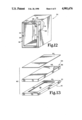
- FIG. 12 is a perspective schematic representation, with portions cut away to show internal details, of the housing of a refrigerator appliance incorporating a sealing and insulating device according to the present invention.
- FIG. 13 is a perspective schematic exploded representation, with portions cut away to show internal details, of a door structure, for example, a door of a refrigerator appliance incorporating a sealing and insulation device according to the present invention.
- FIG. 14 is a schematic cross-sectional view representation of the assembled door structure of FIG. 13.
- FIG. 15 is a perspective view of a sealing and insulation device with an external layer of insulation according to the present invention.
- FIG. 16 is a partial, front elevational view in full section of the FIG. 15 device as positioned in a water heater.
- FIG. 17 is a partial, front elevational view of an appliance with spaces to be insulated.
- FIG. 18 is a fragmentary, perspective view of a sealing and insulation device for use in insulating the spaces of the FIG. 17 appliance.
- the present invention has utility in the manufacture of any number of various products. However, for the sake of clarity and clearness of understanding, but in no way limiting, the present invention will be described in conjunction with the manufacture of a hot water heater device (see FIGS. 1-5 and FIGS. 6-9), a dishwasher installation (see FIGS. 10-11), and the manufacture of a refrigerator (see FIGS. 12-14).
- FIG. 1 schematically illustrates a conventional type water heater device, generally denoted as the numeral 10, having an inner water tank 12 for containing water and an outer shell 14 concentrically surrounding the inner water tank 12.
- the outer shell 14 and inner water tank 12 cooperate to define an annular space 16 therebetween.
- the water heater device 10 is of the gas-fired type having a combustion chamber 18 located at the bottom end of the inner water tank 12.
- a combustion device or gas burner (not shown) is located within the combustion chamber 18.
- the bottom of the annular space 16 can be closed by a bottom wall 20, and the top of the water heater device 10 is closed by a top wall 22.
- a sealing and insulation device 24 is positioned within the annular space 16 in abutting contact with the first or exterior surface of the water tank 12 and the second or interior surface of outer shell 14.
- the sealing and insulation device 24 is shown in FIGS. 2-5 as comprising a closed, elongated envelope 26 fabricated of a resilient, flexible, gas-impermeable material.
- a suitable material for the envelope includes as one option a thermoplastic film such as polyethylene film, or polypropylene film. Another option is a laminate of aluminum foil and polyethylene film.
- the closed envelope 26 is filled with a mass of resilient insulation material 28 such as interengaged or non-interengaged fibrous material, for example, fiberglass, mineral wool, cellulose, ceramic fiber, or divided, discrete particles of material, for example, beads of plastic foam, or a resilient flexible foam, for example, a flexible urethane foam, and the like.
- the specific insulation material used will be a function of the end use and environment.
- the length of the envelope 26 of the insulation device 24 is sufficient to circumscribe the annular space 16 with the ends of the envelope 26 in mutual end-to-end or overlapping abutment.
- the thickness or width dimension of the envelope 26 is at least equal to the transverse dimension of the space 16 so as to be in abutting contact with both the exterior surface of the water tank 12 and interior surface of the outer shell 14 across the space 16.
- Envelope 26 has a substantially circular lateral cross section throughout its length.
- the sealing and insulation device 24 is positioned on the first surface or exterior surface of the inner water tank at a preselected location thereon.
- the sealing and insulation device 24 is wrapped around the circumference of the inner water tank 12 at a location just above the combustion chamber 18.
- the circumscribed envelope 26 is fastened to the exterior surface of the water tank 12 to prevent it from moving. This can be done using for example an adhesive or tape. If the sealing and insulation device 24 is located above the combustion chamber 18, a mat of insulation material 30 of fire resistant material should be located within the space 16 below the sealing and insulation device 24 circumscribing the combustion chamber 18.
- air is evacuated from the interior of the sealing and insulation device 24 creating a negative pressure within the closed cavity of the envelope.
- the presence of this negative pressure causes the volume of the insulation material to shrink and thereby reduce the thickness of the sealing and insulation device 24 to a dimension less than the radial width of the annular space 16 between the first or exterior surface of the water tank 12 and second or interior surface of the outer shell 14.
- the removal of the air can be accomplished by using a vacuum pump 32.
- the vacuum pump 32 has a flexible hose 34 with, for example, a piercing needle at the free inlet end thereof for piercing the envelope 26 of the sealing and insulation device 24.
- the free inlet end of the hose 34 is pressed against the sealing and insulation device 24 so that the needle pierces the envelope 26 establishing gas communication between the inlet end of the hose 34 and interior of the envelope 26.
- the vacuum pump 32 When the vacuum pump 32 is activated, air is removed from the interior of the sealing and insulation device 24 which causes the envelope 26 to shrink in width to at least a dimension less than the transverse dimension of the space 16.
- the outer shell 14 is then positioned coaxially over the inner water tank 12 so that the second or interior surface of the outer shell 14 is in spaced apart relationship to the first or exterior wall surface of the water tank 12.
- the inlet end of the vacuum pump hose 34 is removed from engagement with the sealing and insulation device 24 allowing ambient air to re-enter the envelope 26 of the sealing and insulation device 24 through the pierced hole and thereby release the vacuum.
- the vacuum within the interior cavity is released, the stored energy in the resilient insulation material is released and the insulation begins to return back toward its original size. Since the sealing and insulation device in normal (ambient) condition is larger in thickness than the dimension of the annular space, the device is in abutting contact with both the exterior surface of the water tank 12 and interior surface of the outer shell 14 across the space 16 therebetween circumferentially of the space 16.
- the volume of annular space 16 above the abutting sealing and insulation device 24 is filled with an expanded foam insulation material 38 such as urethane, polyethylene, polystyrene and the like. Expandable foam insulation material is injected or otherwise placed in the annular space 16 above the sealing and insulation device 24, and allowed to expand in situ filling the annular space 16 above the insulation device 24.
- the abutting contact of the sealing and insulation device 24 with the exterior surface of the water tank 12 and interior surface of the outer shell 14 resists the pressure generated by the expanding foaming material 38 and seals across the space 16 to prevent leakage of the foam material past the sealing and insulation device 24 as it is expanding in the space 16 above the sealing and insulation device 24.
- the sealing and insulation device 24 functions to insulate the portion of the space 16 in which it is located and also functions as a seal or stop to the expanding foam material 38 from leaking past the sealing and insulation device 24.
- the sealing and insulation device 24 could be positioned on the interior surface of the outer shell 14, evacuated of air, then have the water tank 12 positioned coaxially within the outer shell 14 in spaced apart relationship to define the space 16. Air is then allowed to re-enter the envelope 26 of the sealing and insulation device 24 (release of the vacuum) and the sealing and insulation device 24 returns back toward its original size such that it expands into contact with both the exterior surface of the tank 12 and interior surface of the shell 14.
- the outer shell 14 can be positioned coaxially over the inner water tank 12 so that the second or interior surface of the outer shell 14 is in spaced apart relationship to the first or exterior wall surface of the water tank 12. Air is then evacuated from the interior of the sealing and insulation device 24 which causes the envelope 26 to shrink in at least the width dimension to a dimension less than the transverse dimension of the space 16.
- the removal of air can be accomplished by, for example, using the vacuum pump 32 as described above.
- the sealing and insulation device 24 is then positioned in the space 16, and when in position the hose is removed from engagement with the sealing and insulation device 24 allowing ambient air to re-enter the envelope 26 through the pierced hole. As the vacuum is released by the entry of ambient air the sealing and insulation device returns toward its normal (ambient) size such that it expands into abutting contact with both the first or exterior surface of the water tank 12 and second or interior surface of the outer shell 14 across the space 16 therebetween.
- the expandable foam insulation material 38 is then introduced into the volume of annular space 16 above device 24 and allowed to expand in situ.
- the hose is removed from engagement with the sealing and insulation device 24, and the pieced hole is sealed by for example a strip of tape before the sealing and insulation device 24 is positioned. Then, after the sealing and insulation device 24 is positioned within the space 16, either the tape is removed and ambient air is allowed to enter through the pierced hole into the sealing and insulation device 24. This entry of air which releases the vacuum allows the sealing and insulation device 24 to expand back to its original size such that it is in abutting contact with both the first surface of the water tank 12 and second surface of the outer shell 14 across the space 16 therebetween.
- an electrically heated water heater generally denoted as the numeral 110, which includes an inner water tank 112 and an outer shell 114 located concentrically over the inner tank 112 with a uniformly wide annular space 116 therebetween.
- the bottom of the water heater 110 is closed by a bottom wall 120 and the top of the water heater 110 is closed by a top wall 122.
- the water heater 110 also includes a control apparatus 123 at the exterior wall surface of the water tank 112.
- the control apparatus 123 includes, for example, heating elements which project into the inner water tank 112 to heat the water contained therein and thermostatic controls for adjusting the heat generated by the heating elements.
- two such control apparatus are utilized at different elevations of the inner tank 112. Access to the control apparatus 123 from the exterior of the water heater 110 is provided for by access apertures 125 formed through the side wall of the outer shell 114 in alignment with the control apparatus 123 and thus the control apparatus 123 is exposed to the exterior of the water heater 110.
- a sealing and insulation device in the shape of a collar.
- the sealing and insulation device 124 includes a centrally located collar opening 127.
- the peripheral configuration of the collar opening 127 matches the peripheral configuration of the access aperture 125.
- the collar opening 127 through the sealing and insulation device 124 receives the control apparatus 123 therethrough.
- the outer perimeter of the sealing and insulation device 124 is larger than the perimeter of the control access aperture 125 formed through the wall of the outer shell 114.
- the width or thickness of the sealing and insulation device 124 has a dimension at least equal to the width of the annular space 116 between the exterior surface of the water tank 112 and the interior surface of the outer shell 114.
- the sealing and insulation device 124 is shown as comprising a closed, envelope 126 fabricated of a resilient, flexible, gas-impermeable material.
- the envelope material can be, for example, a thermoplastic film such as polyethylene film, or polypropylene film. Alternatively, the envelope material can be a laminate of aluminum foil and polyethylene film.
- the closed envelope 126 is filled with a mass of a resilient, flexible insulation material 128 such as interengaged or non-interengaged fibrous material, for example, fiberglass, mineral wool, cellulose, ceramic fiber, or divided, discrete particles of material, for example, beads of plastic foam, or resilient, flexible foam, for example, a flexible urethane foam, and the like.
- a 2-inch or 3-inch normal thickness can be shrunk to at least 1/2 inch when the vacuum is pulled on the envelope cavity.
- the sealing and insulation device 124 is positioned about the perimeter of the control apparatus 123 with the control apparatus 123 projecting into the central opening 127 thereof, and with the back side of the sealing and insulation device 124 in abutment with the first surface or exterior surface of the inner water tank 112.
- the sealing and insulation device 124 can be attached to the inner water tank 112 by a adhesive or tape if required to prevent it from moving.
- air is evacuated from the interior of the sealing and insulation device 124 to shrink it and reduce the thickness or width dimension of the sealing and insulation device 124 to a dimension less than the width of the space 116.
- the removal of the air can be accomplished in the same manner as discussed above in the removal of air from the insulation device 24.
- the outer shell 114 is then positioned coaxially over the inner water tank 112 so that the second or interior surface of the outer shell 114 is in spaced apart relationship to the first or exterior wall surface of the water tank 112, such that the access apertures 125 in the outer shell 114 are in registration with the central openings 127 of the sealing and insulation device 124.
- This alignment applies to the control apparatus 123 so that the control apparatus 123 will be accessible from the outside of the water heater 110.
- the inlet end of the hose 34 is removed from engagement with the sealing and insulation device 124 allowing ambient air to re-enter the envelope 126 through the pierced openings made therein to allow the sealing and insulation device 124 to expand back toward its original size such that it expands into abutting contact with both the exterior surface of the water tank 112 and interior surface of the outer shell 114 across the space 116 therebetween.
- Expandable foam 138 is injected into the volume of space 116 around devices 124 and is allowed to expand in situ filling the space 116 surrounding the sealing and insulation devices 124.
- the sealing and insulating devices 124 function to insulate the space 116 around the control apparatus 123 and, due to its abutting contract with the surfaces of the inner tank 12 and outer shell 14, also functions as a seal or stop to the expanding foam preventing the expanding foam from leaking past the insulation devices 124 and covering the control apparata 123.
- the hose 34 is removed from engagement with the sealing and insulation device 124, and the pierced hole is sealed by, for example, a strip of tape before the sealing and insulation device 124 is positioned. Then, after the sealing and insulation device 124 is positioned within the space 116, the tape is removed and ambient air is allowed to enter through the pierced hole into the sealing and insulation device 124. This entry of air releases the vacuum and allows the sealing and insulation device 124 to expand back to its original size such that it is in abutting contact with both the first surface of the water tank 112 and the second surface of the outer shell 114 across the space 116 therebetween.
- the sealing and insulation device 24 described in conjunction with the gas-heated or fired water heater 10 can be used with the electrically heater water heater 110.
- the sealing and insulation device 24 can be located circumferentially within the annular space 116 adjacent the bottom wall or floor 120 of the water heater 110. The process for installing the insulation device 24 in the water heater 10 discussed above, is followed for installing the sealing and insulation device 24 in the water heater 110.
- a dishwasher apparatus 210 having a housing 212 which is to be installed within the confines of an opening 214 formed in a kitchen cabinetwork 215.
- the exterior surface of the dishwasher housing 212 can be considered a first surface of two spaced apart surfaces, and th edge 218 of the opening 214 can be considered to be a second surface of two spaced apart surfaces.
- a sealing and insulation device 224 is shown as comprising a closed elongated envelope 226 fabricated of a resilient, flexible, gas-impermeable material.
- the material can be, for example, a thermoplastic film such as polyethylene film, or polypropylene film.
- the envelope material may be a laminate of aluminum foil and polyethylene film.
- the closed envelope 226 is filled with a resilient, flexible insulation material 228 such as interengaged or non-interengaged fibrous material, for example, fiberglass, mineral wool, cellulose, ceramic fiber, or divided, discrete particles of material, for example, beads of plastic foam, or resilient, flexible foam such as a flexible urethane foam, and the like.
- the specific insulation material used will be a function of the end use and environment.
- the length of the envelope 226 of the sealing and insulating device 224 is sufficient to overlay the two sides and top side of the dishwasher housing 212.
- the thickness or width dimension of the envelope 226 is at least equal to the transverse dimension of the space 216 between the first or exterior surface of the dishwasher housing 212 and the second or edge 218 of the opening 214 so as to be in abutting contact with both the first and second surfaces across the space 216.
- the width dimension of the sealing and insulation device can be increased up to a width that would entirely cover the housing 212 if desired to give maximum coverage for noise absorption purposes.
- envelope 226 may begin as a substantially straight, elongated tube with a generally circular lateral cross section
- the envelope may also be configured as a three-sided member formed with relatively flat sides and sharp corners to more readily and tightly fit around square or rectangular peripheries.
- it is configured with a generally rectangular lateral cross section throughout its length.
- Each side or length of the frame has four substantially flat surfaces which are substantially parallel and perpendicular as would be expected to create the described lateral cross section.
- the sealing and insulation device 224 is positioned on the exterior surface of the dishwasher housing 212 overlaying the two sides and top side of the housing 212.
- the sealing and insulation device 224 can be attached to the dishwasher housing 212 by, for example, an adhesive, or tape if required to prevent it from moving.
- a vacuum is pulled on the interior of the sealing and insulation device 224 to shrink it and reduce the thickness or with dimension of the sealing and insulation device 224 to a dimension less than the width of the space 216.
- the removal of air can be accomplished in the same manner as discussed above in the removal of air from the sealing and insulation device 24 and 124.
- the dishwasher apparatus 210 is then positioned within the opening 214 of the cabinetwork 215.
- the inlet end of the hose 34 is removed from engagement with the sealing and insulation device 224 allowing ambient air to re-enter the envelope 226 through the pierced openings made therein. This entry of air releases the vacuum and causes the resilient insulation material to return toward its normal or ambient size.
- the sealing and insulation device 224 returns toward its original size such that it is disposed in abutting contact with both the exterior surface of the dishwasher apparatus housing 212 and the edge 218 of the cabinetwork opening 214 across the space 216 therebetween. Once in place, the device completely fills space 216 thus preventing the direct transmission of sound waves into the kitchen environment. It also serves to acoustically insulate by absorbing sound waves generated by the dishwasher.
- the hose 34 is removed from engagement with the sealing and insulation device 224, and the pierced hole is sealed by, for example, a strip of tape before the dishwasher apparatus 210 is positioned within the cabinetwork opening 214. Then after the dishwasher apparatus 210 is positioned, the tape is removed and ambient air is allowed to enter through the pierced hole into the sealing and insulation device 224, or the hose is reconnected to the sealing and insulating device 224. This entry of air which releases the vacuum allows the insulation device 224 to expand back to its original size such that it is in abutting contact with both the exterior surface of the dishwasher housing 212 and the edge 218 of the cabinetwork opening 214 across the space 216.
- FIG. 12 there is shown a refrigerator appliance housing 310 having an inner liner having a wall 312 and an outer case having a wall 314 surrounding the liner wall 312 and cooperating to define a space 316 therebetween.
- a sealing and insulation device 324 comprising a closed envelope 326 fabricated of a resilient, gas-impermeable material such as a thermoplastic film, for example, a polyethylene film or polypropylene film.
- the envelope material may be of a laminate foil and polyethylene film.
- the closed envelope 326 is filled with a resilient, flexible insulation material 328 such as interengaged or non-interengaged fibrous material, for example, fiberglass, mineral wool, cellulose, ceramic fiber, or divided discrete particles of material, for example, beads of plastic foam, or resilient, flexible foam such as a flexible urethane foam, and the like.
- the length of the envelope 326 of the sealing and insulation device 324 is sufficient to circumferentially fit within the space 316 between the inner lining wall 312 and outer case wall 314 at the entrance to the opening 316.
- the thickness or width dimension of the envelope 326 is at least equal to the transverse dimension of the space 316 between the first or inner liner wall surface 312 and the second or case wall surface 314 so as to be in abutting contact with both the first and second surfaces across the space 316.
- the air is evacuated from the interior of the sealing and insulation device 324 to shrink it and reduce the thickness or width dimension to less than the width of th space 316.
- the removal of air can be accomplished in the same manner as discussed above in the removal of air from the sealing and insulation devices 24, 124 and 224.
- the reduced size sealing and insulation device 324 is then positioned within the space 316.
- the inlet end of the hose 34 is removed from engagement with the sealing and insulation device 324 allowing ambient air to re-enter the envelope 326 through the pierced openings made therein to release the vacuum and return the sealing and insulation device 324 back toward its original size such that it is in abutting contact with both the inner liner wall surface 312 and the case wall surface 314 across the space 316 therebetween.
- the hose 34 is removed from engagement with the sealing and insulation device 324, and the pierced hole is sealed by, for example a strip of tape before the sealing and insulation device 324 is positioned into the space 316. Then after the sealing and insulation device 324 is positioned in the space 316, the tape is removed and ambient air is allowed to enter through the pierced hole into the sealing and insulation device 324. This entry of air releases the vacuum and enables the insulation device 324 to expand back to its original size such that it is in abutting contact with both the inner liner wall surface 312 and the outer case wall surface 314 across the space 316.
- the space 316 behind the sealing and insulation device 324 is filled with an expandable foam insulation material 38 such as urethane, polyethylene, polystyrene and the like.
- FIGS. 13 and 14 there is shown a door structure 410 having an exterior door panel 412 and an interior door panel 414.
- the exterior door panel 412 has a peripheral side wall flange 413 extending at 90 degrees to the exterior door panel 412 and a peripheral mounting flange 415 extending at 90 degrees to the free end of the side wall flange 413 back over and generally parallel to the door panel 412.
- the interior door panel 414 fits against the mounting flange 415 in registered, parallel, spaced apart relationship to the exterior door panel 412 defining a space 416 therebetween.
- a sealing and insulation device 424 is shown as comprising a closed generally rectangular envelope 426 fabricated of a resilient, gas-impermeable material.
- the material can be, for example, a thermoplastic film such as polyethylene film, or polypropylene film.
- the material for the envelope may be a laminate of aluminum foil and polyethylene film.
- the closed envelope 426 is filled with a resilient insulation material 428 such as interengaged or non-interengaged fibrous material, for example, fiberglass, mineral wool, cellulose, or discrete particles of material, for example, beads of plastic foam, or resilient, flexible foam, for example, a flexible urethane foam and the like.
- the length and breadth of the envelope 426 is sufficient to overlay the entire surface of the exterior door panel 412 and has a thickness or width dimension at least equal to the transverse dimension of the space 416 between the exterior door panel 412 and interior door panel 414.
- air is evacuated from the interior of the sealing and insulation device 424 to shrink it and reduce the thickness to a dimension less than the width of the space 416 and, therefore, less than the height of the peripheral side wall flange 413.
- the removal of air can be accomplished in the same manner discussed above in the removal of air from the sealing and insulation devices 24, 124, 224 and 324.
- the reduced size sealing and insulation device 424 is then positioned in overlaying disposition on the exterior door panel 412 beneath the peripheral mounting flange 415.
- the inlet end of the hose 34 is removed from engagement with the sealing and insulation device 424 allowing ambient air to be introduced or re-enter the envelope 426 through the pierced openings made therein. This entry of air releases the vacuum and allows the sealing and insulation device 424 to expand back to its original size.
- the interior door panel 414 is then positioned on the peripheral mounting flange 415 in spaced apart parallel relationship to the exterior door panel 412 and fastened thereto. The sealing and insulation device 424 thus fills the space 416 and is in abutting contact with both the exterior door panel 412 and interior door panel 414 transversely across the space 416.
- the hose 34 is removed from engagement with the sealing and insulation device 424, and the pierced hole is sealed by, for example, a strip of tape before the sealing and insulation device 424 is positioned on the exterior door panel 412. Then after the sealing and insulation device 424 is positioned on the exterior door panel 412 beneath the peripheral mounting flange 415, the tape is removed and ambient air is allowed to enter through the pierced holes into the sealing and insulation device 424. This entry of air releases the vacuum and allows the insulation device 424 to expand back toward its original size.
- FIG. 15 a further feature of the present invention is illustrated.
- envelope 526 which is virtually identical to envelope 26 (see FIGS. 1 and 5) and its generally uniform, tubular configuration. In a linear orientation the sides are generally parallel to each other. However, when the envelope is wrapped around a cylindrical member such as tank 12, the envelope orients itself into a form with an inside diameter edge or surface and outside diameter edge or surface. Since the length of material is the same for both diameters, the inside diameter may tend to bunch or gather due to an excess of material. This effect could also be seen with other geometries such as going around corners.
- external insulation layer 510 is applied to a portion of the outer surface 511 of envelope 526.
- Insulation layer 510 may be a foam material or virtually any flexible, resilient insulation material, such as fiberglass. Any number of adhesive bonding agents may be used to apply layer 510 to the envelope such that it remains where positioned.
- the insulation device By arranging the insulation device such that the portion of the envelope which is laminated with the foam layer is disposed against the outer surface of the water tank 12 (see FIG. 16), whatever bunching or gathering of the envelope material may occur, any troughs or channels which would allow leakage of the foam-in-place insulation below the sealing and insulation device, are filled with the external insulation layer. While the external insulation layer 510 is illustrated as being disposed around the inwardly facing surface of envelope 526, this is not a limitation and layer 510 could be disposed at any point around envelope 526 so long as the requisite sealing is achieved.
- FIG. 17 there is a partial, schematic illustration of an appliance to be insulated, either thermally, acoustically or both.
- appliance 540 includes a first portion 541 (such as a freezer section), a second portion 542 (such as a refrigerator section) and two side walls 543 and 544.
- the two portions and two side walls define three spaces 547, 548 and 549 which are to be thermally insulated (or acoustically insulated or both).
- Each space 547, 548 and 549 is generally shaped as a rectangular volume having six sides or surfaces and while some of these sides or surfaces appear open due to the configuration of FIG. 17, there are enclosing walls or surfaces at some point in the appliance structure.
- a flexible envelope of resilient insulation material can be reduced in thickness by pulling a vacuum and installed into the space and the vacuum released.
- the starting thickness of the insulation device 560 might be 11/2 inches, for example, and reduced to 1/2 inch.
- the 1/2 inch thick device is readily and easily inserted into space 548 and then the vacuum is released.
- Abutment pressure remains due to the resiliency of the device and its "memory" in trying to return to its 11/2 inch thickness.
- insulation device 560 begins as a 6-inch thick member (dimension "t") and is structured with a resilient, flexible envelope 561 made of polyethylene film or one of the foregoing mentioned materials for such an envelope.
- the envelope is filled with a mass of flexible, resilient insulation material 562 which in this specific example is fiberglass.
- Envelope 561 is configured as a rectangular "solid” with six substantially parallel and perpendicular sides as would be expected for a box-like shape.
- Valve stem 563 provides the means to draw a vacuum on the interior of device 560. Under appropriate negative pressure the envelope and insulation collapse and the normal or ambient thickness "t" is reduced to a dimension which is less than the thickness of the space to be insulated, in this example, to a thickness less than one inch.
- the valve stem 563 is opened to let a small amount of air in (i.e., release some of the vacuum). As air enters envelope 561, the fiberglass insulation expands. Air is only allowed to enter until the sides of the envelope abut the defining surfaces of the portions 541 and 542, and then the valve stem is closed. The result is to condense an approximately 6-inch thickness of fiberglass leaving the remaining device mostly void of air which is a preferred condition for the prohibition of heat transfer and thereby provide a higher R-value than would be possible with urethane foam.
Landscapes
- Engineering & Computer Science (AREA)
- Physics & Mathematics (AREA)
- General Engineering & Computer Science (AREA)
- Architecture (AREA)
- Mechanical Engineering (AREA)
- Structural Engineering (AREA)
- Civil Engineering (AREA)
- Thermal Sciences (AREA)
- Chemical & Material Sciences (AREA)
- Combustion & Propulsion (AREA)
- Electromagnetism (AREA)
- Acoustics & Sound (AREA)
- Refrigerator Housings (AREA)
- Thermal Insulation (AREA)
Abstract
Description
Claims (18)
Priority Applications (2)
| Application Number | Priority Date | Filing Date | Title |
|---|---|---|---|
| US07/295,554 US4901676A (en) | 1988-04-04 | 1989-01-11 | Sealing and insulation device for the space between spaced apart surfaces |
| CA000595535A CA1329076C (en) | 1988-04-04 | 1989-04-03 | Sealing and insulation device for the space between spaced apart surfaces |
Applications Claiming Priority (2)
| Application Number | Priority Date | Filing Date | Title |
|---|---|---|---|
| US17743988A | 1988-04-04 | 1988-04-04 | |
| US07/295,554 US4901676A (en) | 1988-04-04 | 1989-01-11 | Sealing and insulation device for the space between spaced apart surfaces |
Related Parent Applications (1)
| Application Number | Title | Priority Date | Filing Date |
|---|---|---|---|
| US17743988A Continuation-In-Part | 1986-11-17 | 1988-04-04 |
Publications (1)
| Publication Number | Publication Date |
|---|---|
| US4901676A true US4901676A (en) | 1990-02-20 |
Family
ID=26873291
Family Applications (1)
| Application Number | Title | Priority Date | Filing Date |
|---|---|---|---|
| US07/295,554 Expired - Lifetime US4901676A (en) | 1988-04-04 | 1989-01-11 | Sealing and insulation device for the space between spaced apart surfaces |
Country Status (2)
| Country | Link |
|---|---|
| US (1) | US4901676A (en) |
| CA (1) | CA1329076C (en) |
Cited By (28)
| Publication number | Priority date | Publication date | Assignee | Title |
|---|---|---|---|---|
| US5117810A (en) * | 1991-11-04 | 1992-06-02 | Aos Holding Company | Apparatus for sealing a foam insulated water heater |
| US5160465A (en) * | 1989-02-13 | 1992-11-03 | Exxon Chemical Patents Inc. | Process of insulating a body cavity |
| US5163214A (en) * | 1991-05-08 | 1992-11-17 | Calero Manuel G | Rolling dam method for making water heater |
| EP0524778A1 (en) * | 1991-07-23 | 1993-01-27 | Aos Holding Company | Water heater electric control dam |
| US5212208A (en) * | 1989-02-13 | 1993-05-18 | Exxon Chemical Patents Inc. | Process of insulating a body cavity |
| US5421475A (en) * | 1988-04-04 | 1995-06-06 | Soltech, Inc. | Water heater construction and sealing device therefore |
| US5474202A (en) * | 1993-09-01 | 1995-12-12 | Sabh (U.S.) Water Heater Group, Inc. | Method of making a water heater and an improved water heater structure |
| US5509566A (en) * | 1988-04-04 | 1996-04-23 | Soltech, Inc. | Water heater construction and sealing device therefor |
| WO1997032160A1 (en) * | 1996-02-29 | 1997-09-04 | Stepan Company | Improved pour-in-place water heater foam insulation systems |
| US5987833A (en) * | 1997-06-24 | 1999-11-23 | Owens Corning Fiberglas Technology, Inc. | Vacuum packaged batt |
| US6539955B1 (en) * | 2000-09-29 | 2003-04-01 | Owens Corning Fiberglas Technology, Inc. | Acoustical insulation blanket for dishwasher |
| US20040031801A1 (en) * | 2002-08-16 | 2004-02-19 | Carrier Corporation | Method for improving insulation in hollow metal volumes |
| US20040244728A1 (en) * | 2003-06-03 | 2004-12-09 | Smith Bonnie C. | Combined liquid foam stop and insulator for a tank assembly |
| US20040250402A1 (en) * | 2003-06-13 | 2004-12-16 | Safe Boats International, Llc. | Method of manufacturing foam core boat collars |
| US7013841B1 (en) | 2005-02-01 | 2006-03-21 | Rheem Manufacturing Company | Differently configured fuel-fired water heaters constructed from identical production platforms |
| US20090038980A1 (en) * | 2007-08-06 | 2009-02-12 | Rockwell Anthony L | Insulated tank assembly with insulation stop and method of assembly thereof |
| US20090320886A1 (en) * | 2008-06-30 | 2009-12-31 | Electrolux Home Products, Inc. | Protective arrangement for a control device associated with a dishwashing appliance, and associated apparatus and method |
| US20090320892A1 (en) * | 2008-06-30 | 2009-12-31 | Electrolux Home Products, Inc. | Protective arrangement for a control device associated with a dishwashing appliance, and associated apparatus and method |
| US20100024851A1 (en) * | 2008-08-04 | 2010-02-04 | Rockwell Anthony L | Insulation Element For An Electrical Appliance Such As A Dishwasher |
| US20100087562A1 (en) * | 2007-03-07 | 2010-04-08 | Salvatore Anthony Diloreto | Polyurethane Foam Batt Insulation |
| EP2119841A3 (en) * | 2008-05-16 | 2010-06-16 | Saint-Gobain Isover G+H Ag | Insulation element and method for producing same |
| FR2949130A1 (en) * | 2009-08-11 | 2011-02-18 | Pietro Franco Di | Discrete insulating element for insulation of e.g. roof space in individual house, has complex envelope i.e. ball, in which insulating material is contained when envelope is closed |
| US20110168217A1 (en) * | 2010-01-12 | 2011-07-14 | Neff Raymond A | Appliance comprising polyurethane foam |
| US20110305409A1 (en) * | 2010-06-15 | 2011-12-15 | Russell David D | Self-Supporting Bladder System for a Double Wall Tank |
| US8733052B2 (en) * | 2012-04-20 | 2014-05-27 | Halfen Gmbh | Thermally insulating construction component |
| EP2359737A3 (en) * | 2010-01-29 | 2017-01-25 | BSH Hausgeräte GmbH | Household device with at least one reinforcing body |
| US10422130B2 (en) * | 2015-05-14 | 2019-09-24 | Edgar Hernan Parra Saavedra | Structural system of steel plates and walls with bioclimatic and acoustic application |
| US20220026107A1 (en) * | 2020-07-24 | 2022-01-27 | Haier Us Appliance Solutions, Inc. | Gas-fueled water heater appliance having a foam barrier |
Citations (15)
| Publication number | Priority date | Publication date | Assignee | Title |
|---|---|---|---|---|
| US1874659A (en) * | 1929-08-29 | 1932-08-30 | Upson Co | Insulating material for building and similar purposes |
| US2863179A (en) * | 1955-06-23 | 1958-12-09 | Gen Motors Corp | Refrigerating apparatus |
| US3264165A (en) * | 1964-11-25 | 1966-08-02 | Gen Motors Corp | Insulating means |
| US3307318A (en) * | 1964-02-27 | 1967-03-07 | Dow Chemical Co | Foam plastic filler method |
| US3546846A (en) * | 1965-12-29 | 1970-12-15 | Owens Corning Fiberglass Corp | Method and apparatus for packaging fibrous material |
| US3729879A (en) * | 1971-08-09 | 1973-05-01 | A Franklin | Stick on insulators |
| US3921273A (en) * | 1973-10-09 | 1975-11-25 | Toyota Motor Co Ltd | Method of filling a casing with heat insulating fibers |
| US4172915A (en) * | 1978-07-31 | 1979-10-30 | American Can Company | Thermal insulation |
| US4372028A (en) * | 1980-10-06 | 1983-02-08 | Rheem Manufacturing Company | Method of manufacturing foam insulated tank |
| US4399645A (en) * | 1980-12-15 | 1983-08-23 | Lou Weitz | Bladder insulation |
| US4447377A (en) * | 1979-12-10 | 1984-05-08 | State Industries, Inc. | Method of insulating the exterior of a water heater tank |
| US4477399A (en) * | 1982-06-16 | 1984-10-16 | Gsw Inc. | Method and apparatus for manufacturing a foam insulated water heater |
| US4657798A (en) * | 1984-09-28 | 1987-04-14 | Guilhem Jacques M | Flat composite board |
| US4736509A (en) * | 1987-01-29 | 1988-04-12 | Nelson Thomas E | Method of making water heater construction |
| US4749532A (en) * | 1987-03-20 | 1988-06-07 | A. O. Smith Corporation | Method of and apparatus for fabrication of an insulated fluid storage unit |
-
1989
- 1989-01-11 US US07/295,554 patent/US4901676A/en not_active Expired - Lifetime
- 1989-04-03 CA CA000595535A patent/CA1329076C/en not_active Expired - Fee Related
Patent Citations (15)
| Publication number | Priority date | Publication date | Assignee | Title |
|---|---|---|---|---|
| US1874659A (en) * | 1929-08-29 | 1932-08-30 | Upson Co | Insulating material for building and similar purposes |
| US2863179A (en) * | 1955-06-23 | 1958-12-09 | Gen Motors Corp | Refrigerating apparatus |
| US3307318A (en) * | 1964-02-27 | 1967-03-07 | Dow Chemical Co | Foam plastic filler method |
| US3264165A (en) * | 1964-11-25 | 1966-08-02 | Gen Motors Corp | Insulating means |
| US3546846A (en) * | 1965-12-29 | 1970-12-15 | Owens Corning Fiberglass Corp | Method and apparatus for packaging fibrous material |
| US3729879A (en) * | 1971-08-09 | 1973-05-01 | A Franklin | Stick on insulators |
| US3921273A (en) * | 1973-10-09 | 1975-11-25 | Toyota Motor Co Ltd | Method of filling a casing with heat insulating fibers |
| US4172915A (en) * | 1978-07-31 | 1979-10-30 | American Can Company | Thermal insulation |
| US4447377A (en) * | 1979-12-10 | 1984-05-08 | State Industries, Inc. | Method of insulating the exterior of a water heater tank |
| US4372028A (en) * | 1980-10-06 | 1983-02-08 | Rheem Manufacturing Company | Method of manufacturing foam insulated tank |
| US4399645A (en) * | 1980-12-15 | 1983-08-23 | Lou Weitz | Bladder insulation |
| US4477399A (en) * | 1982-06-16 | 1984-10-16 | Gsw Inc. | Method and apparatus for manufacturing a foam insulated water heater |
| US4657798A (en) * | 1984-09-28 | 1987-04-14 | Guilhem Jacques M | Flat composite board |
| US4736509A (en) * | 1987-01-29 | 1988-04-12 | Nelson Thomas E | Method of making water heater construction |
| US4749532A (en) * | 1987-03-20 | 1988-06-07 | A. O. Smith Corporation | Method of and apparatus for fabrication of an insulated fluid storage unit |
Cited By (46)
| Publication number | Priority date | Publication date | Assignee | Title |
|---|---|---|---|---|
| US5421475A (en) * | 1988-04-04 | 1995-06-06 | Soltech, Inc. | Water heater construction and sealing device therefore |
| US5509566A (en) * | 1988-04-04 | 1996-04-23 | Soltech, Inc. | Water heater construction and sealing device therefor |
| US5160465A (en) * | 1989-02-13 | 1992-11-03 | Exxon Chemical Patents Inc. | Process of insulating a body cavity |
| US5212208A (en) * | 1989-02-13 | 1993-05-18 | Exxon Chemical Patents Inc. | Process of insulating a body cavity |
| US5163214A (en) * | 1991-05-08 | 1992-11-17 | Calero Manuel G | Rolling dam method for making water heater |
| EP0524778A1 (en) * | 1991-07-23 | 1993-01-27 | Aos Holding Company | Water heater electric control dam |
| US5117810A (en) * | 1991-11-04 | 1992-06-02 | Aos Holding Company | Apparatus for sealing a foam insulated water heater |
| US5474202A (en) * | 1993-09-01 | 1995-12-12 | Sabh (U.S.) Water Heater Group, Inc. | Method of making a water heater and an improved water heater structure |
| WO1997032160A1 (en) * | 1996-02-29 | 1997-09-04 | Stepan Company | Improved pour-in-place water heater foam insulation systems |
| US6148774A (en) * | 1996-02-29 | 2000-11-21 | Stepan Company | Pour-in-place water heater foam insulation systems |
| US5987833A (en) * | 1997-06-24 | 1999-11-23 | Owens Corning Fiberglas Technology, Inc. | Vacuum packaged batt |
| US6539955B1 (en) * | 2000-09-29 | 2003-04-01 | Owens Corning Fiberglas Technology, Inc. | Acoustical insulation blanket for dishwasher |
| US20040031801A1 (en) * | 2002-08-16 | 2004-02-19 | Carrier Corporation | Method for improving insulation in hollow metal volumes |
| US6994822B2 (en) * | 2002-08-16 | 2006-02-07 | Carrier Corporation | Method for improving insulation in hollow metal volumes |
| US20040244728A1 (en) * | 2003-06-03 | 2004-12-09 | Smith Bonnie C. | Combined liquid foam stop and insulator for a tank assembly |
| US6941898B2 (en) | 2003-06-03 | 2005-09-13 | Owens Corning Fiberglas Technology, Inc. | Combined liquid foam stop and insulator for a tank assembly |
| AU2004249718B2 (en) * | 2003-06-13 | 2008-11-06 | Safe Boats International L.L.C. | Method of manufacturing foam core boat collars |
| WO2004113016A1 (en) * | 2003-06-13 | 2004-12-29 | Safe Boats International L.L.C. | Method of manufacturing foam core boat collars |
| US7070730B2 (en) | 2003-06-13 | 2006-07-04 | Safe Boats International, Llc | Method of manufacturing foam core boat collars |
| US7201865B2 (en) | 2003-06-13 | 2007-04-10 | Safe Boats International, L.L.C. | Method of manufacturing foam core boat collars |
| US20040250402A1 (en) * | 2003-06-13 | 2004-12-16 | Safe Boats International, Llc. | Method of manufacturing foam core boat collars |
| AU2004249718C1 (en) * | 2003-06-13 | 2009-06-11 | Safe Boats International L.L.C. | Method of manufacturing foam core boat collars |
| US20050023713A1 (en) * | 2003-06-13 | 2005-02-03 | Safe Boats International, Llc | Method of manufacturing foam core boat collars |
| US7013841B1 (en) | 2005-02-01 | 2006-03-21 | Rheem Manufacturing Company | Differently configured fuel-fired water heaters constructed from identical production platforms |
| US20100087562A1 (en) * | 2007-03-07 | 2010-04-08 | Salvatore Anthony Diloreto | Polyurethane Foam Batt Insulation |
| US20090038980A1 (en) * | 2007-08-06 | 2009-02-12 | Rockwell Anthony L | Insulated tank assembly with insulation stop and method of assembly thereof |
| EP2119841A3 (en) * | 2008-05-16 | 2010-06-16 | Saint-Gobain Isover G+H Ag | Insulation element and method for producing same |
| US8398782B2 (en) | 2008-06-30 | 2013-03-19 | Electrolux Home Products, Inc. | Protective arrangement for a control device associated with a dishwashing appliance, and associated apparatus and method |
| US20090320886A1 (en) * | 2008-06-30 | 2009-12-31 | Electrolux Home Products, Inc. | Protective arrangement for a control device associated with a dishwashing appliance, and associated apparatus and method |
| WO2010002843A1 (en) * | 2008-06-30 | 2010-01-07 | Electrolux Home Products, Inc. | Protective arrangement for a control device associated with a dishwashing appliance, and associated apparatus and method |
| US20090320892A1 (en) * | 2008-06-30 | 2009-12-31 | Electrolux Home Products, Inc. | Protective arrangement for a control device associated with a dishwashing appliance, and associated apparatus and method |
| CN102076258B (en) * | 2008-06-30 | 2013-07-10 | 伊莱克斯家用产品公司 | Protective arrangement for a control device associated with a dishwashing appliance, and associated apparatus and method |
| US8293027B2 (en) | 2008-06-30 | 2012-10-23 | Electrolux Home Products, Inc. | Protective arrangement for a control device associated with a dishwashing appliance, and associated apparatus and method |
| US20100024851A1 (en) * | 2008-08-04 | 2010-02-04 | Rockwell Anthony L | Insulation Element For An Electrical Appliance Such As A Dishwasher |
| CN102144255A (en) * | 2008-08-04 | 2011-08-03 | 欧文斯科宁知识产权资产有限公司 | Insulation element for an electrical appliance such as a dishwasher |
| US8205287B2 (en) * | 2008-08-04 | 2012-06-26 | Owens Corning Intellectual Capital, Llc | Insulation element for an electrical appliance such as a dishwasher |
| FR2949130A1 (en) * | 2009-08-11 | 2011-02-18 | Pietro Franco Di | Discrete insulating element for insulation of e.g. roof space in individual house, has complex envelope i.e. ball, in which insulating material is contained when envelope is closed |
| US20110168217A1 (en) * | 2010-01-12 | 2011-07-14 | Neff Raymond A | Appliance comprising polyurethane foam |
| US8302280B2 (en) * | 2010-01-12 | 2012-11-06 | Basf Se | Appliance comprising polyurethane foam |
| EP2359737A3 (en) * | 2010-01-29 | 2017-01-25 | BSH Hausgeräte GmbH | Household device with at least one reinforcing body |
| US20110305409A1 (en) * | 2010-06-15 | 2011-12-15 | Russell David D | Self-Supporting Bladder System for a Double Wall Tank |
| US8899835B2 (en) * | 2010-06-15 | 2014-12-02 | David D. Russell | Self-supporting bladder system for a double wall tank |
| US8733052B2 (en) * | 2012-04-20 | 2014-05-27 | Halfen Gmbh | Thermally insulating construction component |
| US10422130B2 (en) * | 2015-05-14 | 2019-09-24 | Edgar Hernan Parra Saavedra | Structural system of steel plates and walls with bioclimatic and acoustic application |
| US20220026107A1 (en) * | 2020-07-24 | 2022-01-27 | Haier Us Appliance Solutions, Inc. | Gas-fueled water heater appliance having a foam barrier |
| US11592206B2 (en) * | 2020-07-24 | 2023-02-28 | Haier Us Appliance Solutions, Inc. | Gas-fueled water heater appliance having a foam barrier |
Also Published As
| Publication number | Publication date |
|---|---|
| CA1329076C (en) | 1994-05-03 |
Similar Documents
| Publication | Publication Date | Title |
|---|---|---|
| US4901676A (en) | Sealing and insulation device for the space between spaced apart surfaces | |
| US4985106A (en) | Insulation structure for appliances | |
| US5044705A (en) | Insulation structure for appliances | |
| JP3197258B2 (en) | External structure for food storage and manufacturing method thereof | |
| US4744488A (en) | Method and device for manufacturing a foam insulated water heater, and a foam insulated water heater construction | |
| US4771532A (en) | Method of assembling a refrigerator | |
| US5007226A (en) | Insulated refrigerator door construction | |
| US4972967A (en) | Water heater construction and sealing device therefor | |
| GB2084919A (en) | Method of manufacturing foam insulated container | |
| US5229048A (en) | Water heater construction and method of making same | |
| US6029615A (en) | Water heater construction and fabrication method therefor | |
| US5052347A (en) | Water heater construction | |
| US4860728A (en) | Water heater device | |
| US4998970A (en) | Appliance construction including a sealing device | |
| US5040697A (en) | Water heater construction and sealing device therefor | |
| US5509566A (en) | Water heater construction and sealing device therefor | |
| US5024210A (en) | Water heater construction | |
| US4875272A (en) | Method of making spaced-wall appliance with a sealing and insulating device between said walls | |
| US5474202A (en) | Method of making a water heater and an improved water heater structure | |
| US4996759A (en) | Sealing device for an appliance construction | |
| US4956909A (en) | Method of making spaced-wall appliance with a sealing and insulating device between said walls | |
| US4199205A (en) | Refrigerator cabinet construction | |
| US5421475A (en) | Water heater construction and sealing device therefore | |
| US3989328A (en) | Refrigerator cabinet construction | |
| US4311351A (en) | Refrigerator cabinet construction |
Legal Events
| Date | Code | Title | Description |
|---|---|---|---|
| AS | Assignment |
Owner name: SOLTECH, INC., A CORP. OF KY, KENTUCKY Free format text: ASSIGNMENT OF ASSIGNORS INTEREST.;ASSIGNOR:NELSON, THOMAS E.;REEL/FRAME:005371/0442 Effective date: 19890511 |
|
| STCF | Information on status: patent grant |
Free format text: PATENTED CASE |
|
| AS | Assignment |
Owner name: LIBERTY NATIONAL BANK AND TRUST COMPANY OF LOUISVI Free format text: SECURITY INTEREST;ASSIGNOR:SOLTECH, INC.;REEL/FRAME:006268/0587 Effective date: 19920923 |
|
| REMI | Maintenance fee reminder mailed | ||
| FEPP | Fee payment procedure |
Free format text: PAYOR NUMBER ASSIGNED (ORIGINAL EVENT CODE: ASPN); ENTITY STATUS OF PATENT OWNER: LARGE ENTITY |
|
| FPAY | Fee payment |
Year of fee payment: 4 |
|
| SULP | Surcharge for late payment | ||
| FEPP | Fee payment procedure |
Free format text: PAYER NUMBER DE-ASSIGNED (ORIGINAL EVENT CODE: RMPN); ENTITY STATUS OF PATENT OWNER: LARGE ENTITY Free format text: PAYOR NUMBER ASSIGNED (ORIGINAL EVENT CODE: ASPN); ENTITY STATUS OF PATENT OWNER: LARGE ENTITY |
|
| FEPP | Fee payment procedure |
Free format text: PAT HLDR NO LONGER CLAIMS SMALL ENT STAT AS INDIV INVENTOR (ORIGINAL EVENT CODE: LSM1); ENTITY STATUS OF PATENT OWNER: LARGE ENTITY |
|
| FPAY | Fee payment |
Year of fee payment: 8 |
|
| FPAY | Fee payment |
Year of fee payment: 12 |