This application is a continuation of application Ser. No. 017,903, filed Feb. 24, 1987, now abandoned.
FIELD OF THE INVENTION
This invention relates to optical fiber communication systems having at least one central station and a plurality of remote stations connected to the central station.
BACKGROUND OF THE INVENTION
Optical fiber has found widespread application as a long haul transmission medium for voice and data transmission. For instance, substantially all of the newly installed capacity in the long haul portion of the public switched telephone network in the U.S. is optical fiber-based.
Although optical fiber at present is not widely used in the feeder and distribution portion of multi-user networks, e.g., the telephone network, extension of the use of optical fiber into this portion of networks is desirable and is expected to occur within the near future, resulting ultimately in all-optical communication systems.
Since typically the equipment and labor costs for connecting a subscriber, or a group of subscribers, to a central office or other switching station is a major portion of the total cost of a communication system, the ability to provide such connection at relatively low cost is of utmost significance. It is generally true that a large portion (possibly as high as 70-80%) of the media costs (cables, connections, fanouts, enclosures, and pedestals) of a conventional lightguide distribution system is cable cost. Thus, there exists a strong incentive to reduce the amount of cable in a system.
Various architectures for lightguide distribution systems are known. See, for instance, H. Kobrinski, Proceedings of the SPIE, Vol. 568, pp. 42-49, San Diego, August 19, 1985, in which star and ring network configurations are discussed in the context of multiple-access and broadcasting optical fiber networks using dense wavelength division multiplexing (WDM).
Star-type networks are also disclosed in International patent application PCT/GB86/00018 (International Publication No. WO 86/04200). As will be readily appreciated, a star-configured network is generally not very economical with regard to the required length of transmission cable. On the other hand, ring networks may pose, inter alia, access and collision avoidance problems, and frequently do not match well the geometry of residential subscriber networks. Network architectures are also discussed, for instance, in C. A. Brackett, Proceedings, International Communications Conference, Toronto 1986, page 1730; and M. S. Goodman et al., ibid, page 931. Dense channel packing WDM distribution systems of the broadcasting type using coherent detection have been proposed. By a "dense channel packing" WDM system we mean herein a system having at least about 20, frequently more than 50, remote stations, with a typical spacing between wavelengths being 15 nm or less. Components potentially useful in such systems are discussed in T. B. Meriem, Telecommunications Journal, Vol. 52(7), page 408 (1985). Such systems generally require a widely (e.g., more than about 10 nm) tunable local oscillator at each remote station (subscriber). Such oscillators (lasers) are currently not commercially available and can be expected to be relatively costly once they do become available. Furthermore, the use of a widely tunable laser on the subscriber premises can be expected to pose control and stabilization problems.
Prior art dense packing WDM lightguide distribution system architectures thus typically would be relatively costly to implement, since they use relatively large amounts of optical fiber and/or require the use of widely tunable lasers on the customer premises.
Furthermore, WDM architectures which are satisfactory for a small number of wavelengths will frequently not be satisfactory for dense channel packing WDM (e.g., if the number of wavelengths N is greater than about 50). In any realistic system the multiplexing loss and the demultiplexing loss typically should not substantially exceed about 10 dB each. The use of some simple broadband couplers (e.g., balanced Y couplers) to accomplish the multiplexing and demultiplexing can severely limit the number of wavelengths, since each such coupler may introduce a 3 dB loss. See, D. H. McMahon, Journal of the Optical Society of America, Vol. 65(12), pp. 1479-1482 (1975), especially Example 3. On the other hand, narrow band couplers do not necessarily cause such large losses, and might conceivably have an average loss of only about 0.2 dB per coupler, due to unavoidable imperfections, finite passband width, and the like. A simple system that uses only narrow band couplers thus could perhaps accommodate up to about 50 different wavelengths.
In view of the potential importance of end-to-end optical communications, it would be highly desirable to have available a distribution system architecture that requires a relatively small quantity of optical fiber, that does not require the presence of widely tunable laser local oscillators at the remote stations, and that can accommodate a relatively large number of remote stations (subscribers). This application discloses such a system.
SUMMARY OF THE INVENTION
Disclosed is a dense channel packing wavelength division multiplexed optical fiber communication system (e.g., local area network or public switched network) comprising a multiplicity of remote stations (RS) connected to a central station (CS). The inventive system overcomes at least some of the above referred to shortcomings of prior art systems by requiring only a relatively small amount of optical fiber, by not requiring the presence of widely tunable lasers in the remote stations, and by being able to accommodate a relatively large number of remote stations. The inventive system thus offers the potential of high bandwidth (typically sufficient for at least one high resolution video channel), relatively low cost subscriber-to-subscriber optical communications. In preferred embodiments judicious combination of broadband and narrowband couplers makes it possible to accommodate a relatively large number of subscribers.
In particular, the inventive communication system comprises a multiplicity of remote stations RSi (i=1, 2, . . . N), associated with each RSi is a predetermined wavelength λi (all λi are within a predetermined spectral region of width Δλ) and the central station comprises central station generating means adapted for generating electromagnetic radiation of wavelength λ1, λ2, . . . λN. The term "central station" herein is intended to include not only central offices (i.e., local switching facilities) but also remote terminals at which the multiplicity of signals is multiplexed onto a high bandwidth fiber, herein referred to as the "backbone". In preferred embodiments the central station is a central office.
The remote stations are connected to the central station by first optical fiber transmission means that comprise a fiber "backbone" and l fiber "laterals" (1<l<N), with the laterals being connected to the backbone, and substantially every remote station being connected to a lateral, such that radiation from the central station generating means is transmitted through backbone and laterals to the remote stations. Furthermore, each remote station RSi comprises detection means for detecting the electromagnetic radiation of wavelength λi transmitted from the central station through the first optical fiber transmission means, and further comprises wavelength selective means adapted for selecting the radiation of wavelength λi from radiation comprising a multiplicity of wavelengths, such that substantially only the radiation of wavelength λi is detected by the detection means of a given remote station RSi.
The use of a single fiber to carry the traffic for a multiplicity of remote stations RSi between the CS and a point close to the remote stations results in substantial fiber (and cable) savings, e.g., a length reduction by approximately two orders of magnitude, when compared to a simple star architecture. By associating a predetermined wavelength λi with each RSi the need for widely tunable lasers at the RS is eliminated.
In one exemplary embodiment of the invention, the detection means are coherent detections means, and the preferred wavelength selective means comprise a relatively narrow band coupler having a bandwidth that is substantially less than Δλ, exemplarily about 15 nm.
In another exemplary embodiment the detection means are direct detection means, and the first optical fiber transmission means comprise wavelength selective coupling means (e.g., a Fabry-Perot etalon) for selectively coupling radiation from the backbone into the lateral, and the wavelength selective means comprise a narrow band coupler having a bandwidth that is substantially less than Δλ.
BRIEF DESCRIPTION OF THE DRAWINGS
FIGS. 1 and 2 schematically depict exemplary communication systems according to the inention; and
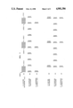
FIG. 3 shows the wavelengths of s)gnals at various points in an exemplary direct detection communicapion system according t the ivention, as well as the pass band wavelengths of two Fabry-Perot etalons in the c/-munication system.
DETAILED DESCRIPTION OF SOME PREFERRED EMBODIMENTS
FIG. 1 schematically depicts an exemplary communicaion system according to the invention, wherein central station 10 is connected by means of backbone fiber 11 (typically a cabled single mode optical fiber) to a cluster of remote stations 13, exemplarily subscriber stations in a housing development, city neighborhood, or the like. The CS 10 typically is connected to one or more other central stations, not shown.
The backbone typically is substantially longer than any of the lateral fibers 12, which are connected to the backbone by known coupling means 14 that are typically contained in a protective housing, conventionally referred to as a closure. For instance, in the U.S. a typical backbone length (CS to closures) is about 6.0 km, and a typical lateral length is about 0.5 km. A given RS typically is joined to a lateral by means of a (typically short) fiber 15, conventionally referred to as a drop, connected to the lateral by known coupling means 16 that are typically contained in a protective housing, conventionally referred to as a pedestal.
Generally two-way communication will be desired, and systems according to the invention can accommodate, in addition to outbound (CS to RS) also inbound (RS to CS) signal transmission. This is advantageously accomplished by, inter alia, use of 2-fiber drops (not shown), and provision of a backbone fiber 17 connected to the laterals by coupling means 14', as shown in FIG. 1. Other techniques for obtaining a two-way communication capability are known (e.g., using a single backbone for bothinbound and outbound signals), but are at present not considered to be preferred.
Although the RS typically are connected to the CS via drops, laterals, and a backbone, an inventive communication system may in some cases also comprise a relatively small number of RS that are connected to the CS via drops and backbone, or even via backbone only, as will be appreciated by those skilled in the art. Furthermore, more than one RS can be connected to a given lateral by a single drop, or be connected to the lateral at a single pedestal. Similarly, more than one lateral can be connected to the backbone at a single enclosure. Furthermore, it is possible that a given wavelength λi be associated with more than one remote station,and/or that one or more remote stations each may cosist of a multiplicity of subscribers. In the latter case time division multiplexing (or any other appropriate scheme) may, if desired, be employed to provide each subscriber with private communication means. All such obvious modifications of the basic inventive architecture are contemplated. However, in order to simplify the exposition, from hereon the discussion will be in terms of the exemplary simple matrix-like architecture of FIGS.1 and 2, in which it is assumed that a one-to-one relationship exists between RSi and λi.
Associated with each connection point (e.g., 14 and/or 16 of FIG. 1) is a certain amount of signal loss, and it is generally advantageous to arrangethe system layout such that this signal loss is minimized. For a system of N remote stations RSi (i=1, 2, . . . N), and l laterals (1<l<N), withd drops per lateral, it can easily be shown that the signal loss associatedwith connection points is minimal if d=l=N1/2. Thus, a distribution system according to the invention is advantageously laid out substantiallyas a square "matrix", with l laterals (columns) and, ideally d=l drops per lateral (rows).
We envisage that communication systems according to the invention typicallywill have a substantial number of RS, frequently N>50. All the wavelengths λi associated with the N remote stations RSi are typically in the approximate range 1.25-1.6 μm, provided the optical fibers are silica-based optical fibers of the type that is currently generally used. Although presently not preferred, an inventive communication system could also be operated in a different spectral region, e.g., in a range that includes 0.8 μm.
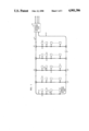
FIG. 2 schematically depicts an exemplary distribution system according to the invention, the system having N=l2 remote stations, l laterals 121, 122, . . . , 12l, with l remote stations served by each lateral. It will of course be appreciated that such regularity is not a requirement ofthe invention. FIG. 2 also shows central station 10 with associated transmitters/receivers X1, X2, . . . Xl 2. As shown, each RSi has an associated Xi. However, this is not necessarily so. For instance, if the transmitter lasers are widely tunable and, depending, inter alia, on traffic load, a given transmitter/receiver may serve two or more RS, or no predetermined assignment of transmitter/receiver to RS may be made. Connections to other central stations are typically present but are not shown.
In one embodiment the communication system of FIG. 2 comprises coherent detection. For background on coherent systems see, for instance, P. S. Henry, IEEE Journal of Quantum Electronics, Vol. QE-21(12), page 1862, andProceedings of the National Communications Forum, Chicago, 1982, page 353.
In a coherent distribution system according to the invention, couplers 14 typically are wideband couplers (i.e., their properties are substantially independent of wavelength over the relevant range of wavelengths) that divert a predetermined fraction of the radiation power into the lateral. Although the diverted fraction can be the same at all couplers, it is preferable to select the couplers such that each lateral receives approximately the same radiation power. For instance, selecting the couplers 14 such that the coupling ratios into laterals 122, 123, . . . 12l are 1:1, 2:1, . . . (l-1):1, respectively, results in substantially equal power in each of the laterals. Broadband couplers that can perform this function are well known. For instance, a broadband coupler whose splitting ratio is adjustable is commercially available from Fibernetics of Belmont, CA.
In a coherent distribution system as shown in FIG. 2 the wavelengths λi are chosen such that no two wavelengths differ by less thansome amount δλ, which can in principle be even less than 0.01 nm. However, in practice δλ will frequently be substantially larger, e.g., of the order of 1 nm. For instance, in an exemplary distribution system serving 144 remote stations, the wavelengths can be chosen such that the wavelengths in a given "row" (of the matrix formed bythe RS, as depicted in FIG. 2) are 1 nm apart, and in a given "column" are 15 nm apart, extending from about 1430 nm to about 1606 nm (Δλ=176 nm).
In a preferred embodiment of the inventive coherent distribution system, couplers 16 advantageously are wavelength selective couplers having a bandwidth substantially less than Δλ, exemplarily about 15 nm. The narrow band couplers are chosen such that λi is located approximately centrally within the passband of the coupler associated with any given RSi. Couplers that meet the requirements are known, e.g., dielectric interference filters and gratings. See, for instance, J. Lipson et al, Journal of Lightwave Technology, LT-1, page 387(1983).
In the coherent distribution system according to the invention, each RSi comprises a local oscillator (laser) that emits radiation nominally of wavelength λi, to be "mixed" with the radiation that is coupled into RSi from the lateral by means of connector 16 ina known manner. As will be appreciated by those skilled in the art, although both the wavelength from the CS and the local oscillator wavelength are nominally λi, there is actually a small difference between the two (corresponding typically to a frequency difference on the order of a GHz or so). The difference typically is predetermined, such that a pre-set electronic filter can be used in the coherent detection. It thus may be advantageous to provide a local oscillator that is tunable, but tunability over only a narrow range of wavelengths (typically<1 nm) is required. A coherent detection system may also require polarization drift compensation means at each RS.
As will be appreciated by those skilled in the art, an inventive coheret distrybution system with a sufficiently generous loss budget could, in princaple, use wideband couplers instead of the currently preferred narrowband couplers to connect some or all RS to the laterals, s)nce the coherentdetec4ion process itself provides wavelength selectivity.
In another embodiment, the distribution system of FIG. 2 uses direct (non-coherent) detection Of the signal radiation λi at any RSi. In a preferred embodiment of the inventive direct detection distribution system, couplers 14 are Fabry-Perot etalons (see, for instance, T. B. Meriem, op. cit.) or Bragg reflection fiber directional couplers (see, for instance, M. S. Whalen et al., Electronics Letters, Vol. 22, pp. 681-682, (1986)) and couplers 16 are narrow band couplers (see, for instance, J. Lipson et al., op. cit.). In this way it can be assured that essentially only radiation of wavelength λi reaches the detector of RSi, and that the losses in the system are kept relatively low.
FIG. 3 illustrates an exemplary wavelength assignment and filtering scheme for a direct detection communication system as depicted in FIG. 2, having 10 laterals of 10 RS each. The wavelengths λi are arranged in 10 groups of 10, as indicated in line (a) of FIG. 3. Each Fabry-Perot (F-P) etalon is designed to pick out one wavelength from each group of wavelengths, to couple these 10 wavelengths into the lateral associated with the etalon, and to pass all other wavelengths with minimal attenuation. This is illustrated in lines (b) and (c) of FIG. 3 with respect to the F-P coupler associated with the first lateral (which is 1210 in FIG. 2, since l is assumed to be 10) and in lines (d), (e) and (f), FIG. 3 with regard to the F-P coupler associated with lateral 122 of FIG. 2. In the exemplary scheme, the wavelengths propagating in any given lateral are spaced 20 nm apart, and thus can be easily separated by known means.
Preferred embodiments of the invention allow for inbound as well as outbound communication. In such embodiments the RS comprise radiation generating means (typically a laser), and the CS comprises radiation detection means.
In particular, a given RSi comprises radiation generating means adapted for emitting radiation nominally of wavelength λi. As will be appreciated by those skilled in the art, it will frequently be advantageous if the radiation received by a given RSi is not of exactly the same wavelength as the radiation transmitted by the RSi, but differs by a small amount (e.g., corresponding to about 10 GHz in a coherent detection system) in order to avoid interference between outboundand inbound signals.
In a two-way communication system according to the invention the CS detection means can comprise coherent or direct detection means, and can be arranged in any appropriate manner. For instance, CS detection means can be associated with RS generation means, on a one-to-one basis, as shown schematically in FIG. 2. In preferred embodiments the same detectiontype (coherent or direct) is used both in the RS and CS, but combinations of coherent and direct detection are also envisaged. In general, the CS ina two-way communication system according to the invention comprises D detectors (1≦D≦N) connected to the inbound fiber transmission means by means that comprise wavelength selective couplers which insure that any given CS detector receives, at any given time, substantially only radiation from at most one RS.