US4901179A - Magnetic head having a laminated structure - Google Patents
Magnetic head having a laminated structure Download PDFInfo
- Publication number
- US4901179A US4901179A US07/161,408 US16140888A US4901179A US 4901179 A US4901179 A US 4901179A US 16140888 A US16140888 A US 16140888A US 4901179 A US4901179 A US 4901179A
- Authority
- US
- United States
- Prior art keywords
- magnetic
- magnetic head
- sub
- head
- gap
- Prior art date
- Legal status (The legal status is an assumption and is not a legal conclusion. Google has not performed a legal analysis and makes no representation as to the accuracy of the status listed.)
- Expired - Lifetime
Links
Images
Classifications
-
- G—PHYSICS
- G11—INFORMATION STORAGE
- G11B—INFORMATION STORAGE BASED ON RELATIVE MOVEMENT BETWEEN RECORD CARRIER AND TRANSDUCER
- G11B5/00—Recording by magnetisation or demagnetisation of a record carrier; Reproducing by magnetic means; Record carriers therefor
- G11B5/127—Structure or manufacture of heads, e.g. inductive
- G11B5/187—Structure or manufacture of the surface of the head in physical contact with, or immediately adjacent to the recording medium; Pole pieces; Gap features
- G11B5/21—Structure or manufacture of the surface of the head in physical contact with, or immediately adjacent to the recording medium; Pole pieces; Gap features the pole pieces being of ferrous sheet metal or other magnetic layers
-
- G—PHYSICS
- G11—INFORMATION STORAGE
- G11B—INFORMATION STORAGE BASED ON RELATIVE MOVEMENT BETWEEN RECORD CARRIER AND TRANSDUCER
- G11B5/00—Recording by magnetisation or demagnetisation of a record carrier; Reproducing by magnetic means; Record carriers therefor
- G11B5/127—Structure or manufacture of heads, e.g. inductive
- G11B5/147—Structure or manufacture of heads, e.g. inductive with cores being composed of metal sheets, i.e. laminated cores with cores composed of isolated magnetic layers, e.g. sheets
- G11B5/1475—Assembling or shaping of elements
Definitions
- the present invention relates to a magnetic head, and particularly pertains to a magnetic head suitable for a video-tape recorder.
- ferrite is widely used as core material of magnetic head, because it has high wear resistance. But, since its saturation magnetization, Bs, is lower than alloy-material by 30%-50%, when ferrite is used for high density recording media which has been put to practical use lately, magnetic saturation of the head core becomes a problem. From a view point of the above, a magnetic head comprising permalloy or sendust has been put into practice for high density recording media.
- amorphous alloy draws attention as splended material in both of wear resistance and magnetic characteristic.
- a laminated structure is generally employed in order to avoid eddy current loss in the high frequency range, since specific resistance of the core material per se is low (70-120 ⁇ cm).
- track width is comparatively large and is several hundred ⁇ m in thickness, and further, its frequency range is lower, therefore the thickness of a core is relatively large and is 200-300 ⁇ m in thickness; in order to form a lamination, gap formation, adhesive such as epoxy resin or the like, is used.
- track width is very small, for instance several scores ⁇ m, and further, since gap length is very short, for instance, less than 0.3 ⁇ m, it is difficult to keep the gap length in high precision by using an adhesive.
- desirable thickness of a core is less than 10 ⁇ m.
- a method wherein thin layer of amorphous alloy or sendust alloy as magnetic material is prepared by adopting sputtering method or vapor deposition method.
- SiO 2 is used as interface insulation material. And further, as gap spacer material, employment of the SiO 2 is well known.
- the magnetic material of metal tape selectively accumulates around SiO 2 used as interface insulation material in magnetic head comprising thin sheets of metal magnetic material. Because of this accumulation, spacing takes place between the magnetic head and tape, and head output lowers on account of spacing loss.
- the present invention is intended to solve the above-mentioned problem of the prior art, and the purpose of the present invention is to obtain a magnetic head on which magnetic material component of tape does not accumulate, thereby to provide a stable head output.
- the magnetic head of the present invention is characterized in that its tape contact surface comprises a section of multi layered structure of magnetic substance, and
- At least one interface insulation material between the layers of said magnetic substance of multi layered structure and comprising the gap spacer material comprises one member selected from the group comprising oxides, complex oxides, nitrides and carbides of transition metal elements, IIa group elements of the periodic table and Zn.
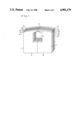
- FIG. 1 is a perspective view showing a magnetic head as an embodiment of the present invention.
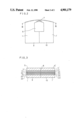
- FIG. 2 is a plan view showing a magnetic head as an embodiment of the present invention.
- FIG. 3 is a sectional view taken on line III--III of FIG. 2.
- Substrate material of a non-magnetic metal such as brass
- a mirror-grinding and washed sufficiently thus to obtain a substrate 1.
- the substrate 1 is put into a known vacuum chamber depressed to 3 ⁇ 10 -7 Torr.
- Ar gas is supplied to the vacuum chamber to a pressure of 2 ⁇ 10 -2 Torr, amorphous alloy layer 2a on the substrate 1 is made by sputtering wherein component of target is 81 atomic % Co, 13 atomic % Nb and 6 atomic % Zr.
- a layer 3a of the interface insulation material having thickness of 1000 ⁇ is disposed on the amorphous alloy layer 2a by sputtering at Ar pressure of 4 ⁇ 10 -2 Torr.
- amorphous alloy layers 2b, 2c and interface insulation material layer 3b are sputtered alternately to form 2b, 3b and 2c, in this order on the amorphous alloy layer 2a, and thus triple-layered structure block is obtained.
- substrate 5 material of which is the same as that of substrate 1 is adhered to amorphous alloy layer 2c with bonding glass layer 4 therebetween, thus a laminated core is obtained.
- a winding aperture 6 is engraved on the gap forming face of the laminated core. And, after carrying out a mirror-grinding by using diamond paste on the gap forming surface, the gap spacer material is sputtered on that surface to a predetermined thickness, thus a laminated core block 9 to form one side of a magnetic head is completed.
- Another laminated core block 10 having the same components 1' to 5' as the block 9 is made in accordance with the same process as the above-mentioned.
- This magnetic head was attached to a video tape recorder (relative speed of tape was 3.8 m/sec), and, tape running tests were carried out in various environments, using general metal particulate tape.
- a video tape recorder relative speed of tape was 3.8 m/sec
- tape running tests were carried out in various environments, using general metal particulate tape.
- SiO 2 is used as interface insulation material or gap spacer material
- considerable drop of head output was observed.
- stable head output was obtained in all environments of the tests.
- the outputs of the magnetic head of the present invention at a temperature of 23° C. and a relative humidity of 10% obtained by the tests are shown in Table 1 with the output of a conventional magnetic head as a comparison sample.
- the head outputs are relative values taking head output at a temperature of 23° C. and relative humidity of 70% as 0 (dB).
- non magnetic stainless steel as substrate is put into a vacuum chamber depressured to 5 ⁇ 10 -7 Torr; after Ar gas is provided in the vacuum chamber to a pressure of 1.5 ⁇ 10 -3 Torr, sputtering is carried out to the substrate taking a sendust alloy (Fe 84.5 wt %, Si 9.7 wt % Al 5.8 wt %) as target of the sputtering. And then, taking interface insulation material as target, sputtering is carried out to the sendust layer at Ar gas pressure of 4 ⁇ 10 -2 Torr, thus interface insulation material of about 1000 ⁇ in thickness is formed.
- a sendust alloy Fe 84.5 wt %, Si 9.7 wt % Al 5.8 wt
- Table 2 shows magnetic permeability of the resultant layers at a frequency of 100 KHz with a magnetic field of 1 mOe.
- the magnetic permeabilities in Table 2 are the values wherein only the thickness of the magnetic material is taken into account and the interface insulation material is neglected because of their small thickness.
- a magnetic head having a sandwich structure wherein a head core is put between substrates is used, but, similar effects are realized in a magnetic head wherein the whole area of the tape contact surface consists of magnetic substance of multi layered structure.
- Tables 1 and 2 show limited varieties of components of oxides, complex oxides, nitrides and carbides of transition metal elements, IIa group elements of the periodic table and Zn. But it is not necessary that the component is limited to those shown in Tables 1 and 2. So far as the component is in a practically permissible range, that is, the component is a substantial part of the material, the above-mentioned effect is realized, even if the said materials contain some impurities or there is some difference between the target component and the material component.
- magnetic material is amorphous alloy of Co-Nb-Zr system, but other alloys, such as Co-Fe-Si-B system and Ni-Si-B system show similar effects. And further the magnetic material is not restricted to the sputtering material, but ribbon amorphous made by melt quenching method or thin layer made by vapor deposition method or the like can be used as the magnetic material.
- component of the sendust alloy is not restricted, and is effective in Fe-Si-Al alloy system. Therefore, permalloy (Fe-Ni alloy) as alloy magnetic material can be expected to have a similar effect, because magnetic permeability greatly effects magnetostriction.
- material comprising oxides, complex oxides, nitrides or carbides of the transition metal elements, IIa group elements of the periodic table and Zn are used as interface insulation material or gap spacer material for a magnetic head made of magnetic substance having a multi layered structure, the magnetic material component in a tape no longer on the magnetic head when running in various practical environments. Accordingly stable head output is obtained and a highly reliable magnetic head is realized.
- the thermal expansion coefficient of the interface insulation material is larger by another digit than that of conventional material, and the interface insulation material becomes more like metal magnetic material.
Abstract
Tape contact surface of a magnetic head is made of magnetic substance of multi-layered structure; interface insulation material for said multi layered structure and/or gap spacer material are made of oxides, complex oxides, nitrides and carbides of transition metal elements, IIa group elements of the periodic table and Zn; and accumulation of magnetic material from magnetic tape is prevented and output of magnetic head is stabilized.
Description
This is a continuation of application Ser. No. 829,070 filed Feb. 13, 1986, now abandoned.
1. Field of Invention
The present invention relates to a magnetic head, and particularly pertains to a magnetic head suitable for a video-tape recorder.
2. Description of the Related Art
Hitherto, ferrite is widely used as core material of magnetic head, because it has high wear resistance. But, since its saturation magnetization, Bs, is lower than alloy-material by 30%-50%, when ferrite is used for high density recording media which has been put to practical use lately, magnetic saturation of the head core becomes a problem. From a view point of the above, a magnetic head comprising permalloy or sendust has been put into practice for high density recording media.
On the other hand, amorphous alloy draws attention as splended material in both of wear resistance and magnetic characteristic.
In case that those alloys are used as core material of a magnetic head, a laminated structure is generally employed in order to avoid eddy current loss in the high frequency range, since specific resistance of the core material per se is low (70-120 μφ·cm).
In an audio head, track width is comparatively large and is several hundred μm in thickness, and further, its frequency range is lower, therefore the thickness of a core is relatively large and is 200-300 μm in thickness; in order to form a lamination, gap formation, adhesive such as epoxy resin or the like, is used.
In case of magnetic heads for VTRs, computer memory devices and various data recorders, track width is very small, for instance several scores μm, and further, since gap length is very short, for instance, less than 0.3 μm, it is difficult to keep the gap length in high precision by using an adhesive.
Furthermore, in case that track width is small and using frequency in a range of several MHz-10 MHz and is comparatively high; desirable thickness of a core is less than 10 μm.
However, it is difficult to prepare a core having such a small thickness in the present technology; and furthermore even in a structure comprising ribbon-amorphous or ribbon-sendust, it is difficult to attain a uniform thickness of core, when the thickness of the core is less than 20 μm.
From a viewpoint of the above, a method wherein thin layer of amorphous alloy or sendust alloy as magnetic material is prepared by adopting sputtering method or vapor deposition method.
By using these methods, a core having thickness of less than 10 μm is obtained easily, and since it is possible to laminate magnetic material and interface insulation material alternately and adhesion strength between each material is large, it is possible to retain the gap with the above-mentioned high precision.
In such prior art, it is well known that SiO2 is used as interface insulation material. And further, as gap spacer material, employment of the SiO2 is well known.
Using such a coventional magnetic head comprising lamination magnetic core made of metal magnetic material and SiO2 as interface insulating material, running tests for conventional metal particulate tape were made in various environment. As a result, it was found that particularly in low humidity environment, head output was greatly lowered. Observing a tape contact surface of the head, output of which was lowered, selective accumlation was found around the section of the SiO2 as interface insulation material. As a result of measurement by surface analyzer, thickness of the accumlation was 500-600 A. The cumulation was analyzed by Auger analysis method, and it was found that the component of accumulation was magnetic material component in the metal tape, and further, for thickness of the accumulation both data based on the surface analyzer and the Auger analysis method agreed with each other. And further, little accumulation was observed on the gap.
Collectively considering the above, it is found that when metal particulate tape runs in low humidity environment, the magnetic material of metal tape selectively accumulates around SiO2 used as interface insulation material in magnetic head comprising thin sheets of metal magnetic material. Because of this accumulation, spacing takes place between the magnetic head and tape, and head output lowers on account of spacing loss.
On the other hand, as number of laminations increases steadily, a trend of decrease of permeability (μ') is observed, though thickness of magnetic material is kept the same. This is because the magnetostriction constant (λs) has not become zero perfectly, and besides the thermal expansion coefficient (α) of magnetic material is more than ten times as large as that of SiO2.
The present invention is intended to solve the above-mentioned problem of the prior art, and the purpose of the present invention is to obtain a magnetic head on which magnetic material component of tape does not accumulate, thereby to provide a stable head output.
The magnetic head of the present invention is characterized in that its tape contact surface comprises a section of multi layered structure of magnetic substance, and
at least one interface insulation material between the layers of said magnetic substance of multi layered structure and comprising the gap spacer material comprises one member selected from the group comprising oxides, complex oxides, nitrides and carbides of transition metal elements, IIa group elements of the periodic table and Zn.
FIG. 1 is a perspective view showing a magnetic head as an embodiment of the present invention.
FIG. 2 is a plan view showing a magnetic head as an embodiment of the present invention.
FIG. 3 is a sectional view taken on line III--III of FIG. 2.
In the following, one embodiment of the present invention is elucidated with reference to FIGS. 1 and 2.
Substrate material of a non-magnetic metal, such as brass, is subject to a mirror-grinding and washed sufficiently, thus to obtain a substrate 1. The substrate 1 is put into a known vacuum chamber depressed to 3×10⁻⁷ Torr. After Ar gas is supplied to the vacuum chamber to a pressure of 2×10⁻² Torr, amorphous alloy layer 2a on the substrate 1 is made by sputtering wherein component of target is 81 atomic % Co, 13 atomic % Nb and 6 atomic % Zr.
Next, taking interface insulation material as target of sputtering, a layer 3a of the interface insulation material having thickness of 1000 Å is disposed on the amorphous alloy layer 2a by sputtering at Ar pressure of 4×10⁻² Torr.
Thereafter, in a similar way to the above, amorphous alloy layers 2b, 2c and interface insulation material layer 3b are sputtered alternately to form 2b, 3b and 2c, in this order on the amorphous alloy layer 2a, and thus triple-layered structure block is obtained.
On the other hand, substrate 5, material of which is the same as that of substrate 1 is adhered to amorphous alloy layer 2c with bonding glass layer 4 therebetween, thus a laminated core is obtained.
Next, a winding aperture 6 is engraved on the gap forming face of the laminated core. And, after carrying out a mirror-grinding by using diamond paste on the gap forming surface, the gap spacer material is sputtered on that surface to a predetermined thickness, thus a laminated core block 9 to form one side of a magnetic head is completed.
Another laminated core block 10 having the same components 1' to 5' as the block 9 is made in accordance with the same process as the above-mentioned.
And then the gap forming faces of the blocks 9, 10 are abutted to each other with bonding glass 7 therebetween, to form the gap 8. After being worked to predetermined shape, a magnetic head is completed.
This magnetic head was attached to a video tape recorder (relative speed of tape was 3.8 m/sec), and, tape running tests were carried out in various environments, using general metal particulate tape. As a result of the running tests, in the conventional magnetic head wherein SiO2 is used as interface insulation material or gap spacer material, considerable drop of head output was observed. But, in the magnetic head of the present invention, stable head output was obtained in all environments of the tests.
The outputs of the magnetic head of the present invention at a temperature of 23° C. and a relative humidity of 10% obtained by the tests are shown in Table 1 with the output of a conventional magnetic head as a comparison sample. In Table 1, the head outputs are relative values taking head output at a temperature of 23° C. and relative humidity of 70% as 0 (dB).
                                  TABLE 2
__________________________________________________________________________
                                 Magnetic
        Thermal Sendust alloy layer
                                 perme-
Interface
        expansion
                Thickness   Total
                                 ability
insulation
        coefficient
                of one
                      Lamination
                            thickness
                                 μ'
material
        α(× 10.sup.-7 /°C.)
                layer (μm)
                      number
                            (μm)
                                 (100 KHz, 1mOe)
__________________________________________________________________________
SiO.sub.2
        4       10    3     30.3 2000
(Conventional   3     10    30.9 800
material)
ZnFe.sub.2 O.sub.4
        85      10    3     30.3 2500
                3     10    30.9 2300
Mg.sub.2 TiO.sub.4
        90      10    3     30.3 2700
                3     10    30.9 2400
NiMnO.sub.2
        115     10    3     30.3 3000
                3     10    30.9 2900
SrTiO.sub.3
        100     10    3     30.3 2800
                3     10    30.9 2700
α-Fe.sub.2 O.sub.3
        105     10    3     30.3 2900
                3     10    30.9 2800
TiN     94      10    3     30.3 2700
                3     10    30.9 2500
TiC     76      10    3     30.3 2500
                3     10    30.9 2200
WC      73      10    3     30.3 2400
                3     10    30.9 2150
ZrC     67      10    3     30.3 2400
                3     10    30.9 2050
TaC     82      10    3     30.3 2600
                3     10    30.9 2300
__________________________________________________________________________
Next, non magnetic stainless steel as substrate is put into a vacuum chamber depressured to 5×10⁻⁷ Torr; after Ar gas is provided in the vacuum chamber to a pressure of 1.5×10⁻³ Torr, sputtering is carried out to the substrate taking a sendust alloy (Fe 84.5 wt %, Si 9.7 wt % Al 5.8 wt %) as target of the sputtering. And then, taking interface insulation material as target, sputtering is carried out to the sendust layer at Ar gas pressure of 4×10⁻² Torr, thus interface insulation material of about 1000 Å in thickness is formed.
Hereinafter, in a way similar to the above the sendust alloy layer and the interface insulation material layer are laminated alternately, thus obtaining multi layered sendust.
Table 2 shows magnetic permeability of the resultant layers at a frequency of 100 KHz with a magnetic field of 1 mOe. The magnetic permeabilities in Table 2 are the values wherein only the thickness of the magnetic material is taken into account and the interface insulation material is neglected because of their small thickness.
              TABLE 1
______________________________________
Interface insulation
             Gap spacer     23° C. 10%
material     material       Relative humidity
(Target material)
             (Target material)
                            head output (dB)
______________________________________
SiO.sub.2 (Conventional
             SiO.sub.2 (Conventional
                            -4
material)    material)
α-Fe.sub.2 O.sub.3
             SiO.sub.2 (Conventional
                            -0.5
             material
MgNiO.sub.2  SiO.sub.2 (Conventional
                            -0.3
             material)
MgMnO.sub.2  SiO.sub.2 (Conventional
                            -0.5
             material)
Mg.sub.2 TiO.sub.4
             SiO.sub.2 (Conventional
                            -0.2
             material)
SrTiO.sub.2  SiO.sub.2 (Conventional
                            -0.5
             material)
NiMnO.sub.2  SiO.sub.2 (Conventional
                            -0.5
             material)
ZnFe.sub.2 O.sub.4
             SiO.sub.2 (Conventional
                            -0.2
             material)
α-Fe.sub.2 O.sub.3
             α-Fe.sub.2 O.sub.3
                            0
MgNiO.sub.2  SrTiO.sub.2    0
NiMnO.sub.2  ZnFe.sub.2 O.sub.4
                            0
ZnFe.sub.2 O.sub.4
             ZnFe.sub.2 O.sub.4
                            0
______________________________________
In the above-mentioned embodiment, a magnetic head having a sandwich structure wherein a head core is put between substrates is used, but, similar effects are realized in a magnetic head wherein the whole area of the tape contact surface consists of magnetic substance of multi layered structure.
And further, Tables 1 and 2 show limited varieties of components of oxides, complex oxides, nitrides and carbides of transition metal elements, IIa group elements of the periodic table and Zn. But it is not necessary that the component is limited to those shown in Tables 1 and 2. So far as the component is in a practically permissible range, that is, the component is a substantial part of the material, the above-mentioned effect is realized, even if the said materials contain some impurities or there is some difference between the target component and the material component.
In the above-mentioned embodiment, magnetic material is amorphous alloy of Co-Nb-Zr system, but other alloys, such as Co-Fe-Si-B system and Ni-Si-B system show similar effects. And further the magnetic material is not restricted to the sputtering material, but ribbon amorphous made by melt quenching method or thin layer made by vapor deposition method or the like can be used as the magnetic material.
Furthermore, component of the sendust alloy is not restricted, and is effective in Fe-Si-Al alloy system. Therefore, permalloy (Fe-Ni alloy) as alloy magnetic material can be expected to have a similar effect, because magnetic permeability greatly effects magnetostriction.
As mentioned above, in the present invention, since, material comprising oxides, complex oxides, nitrides or carbides of the transition metal elements, IIa group elements of the periodic table and Zn are used as interface insulation material or gap spacer material for a magnetic head made of magnetic substance having a multi layered structure, the magnetic material component in a tape no longer on the magnetic head when running in various practical environments. Accordingly stable head output is obtained and a highly reliable magnetic head is realized.
By using the material of the present invention as interface insulation material, the thermal expansion coefficient of the interface insulation material is larger by another digit than that of conventional material, and the interface insulation material becomes more like metal magnetic material. Thereby, especially in case the number of lamination layers increases, or the thickness of one layer becomes thin, the influence of stress on the magnetic material becomes small, and accordingly deterioration of the magnetic head becomes small.
Claims (5)
1. A magnetic head having a tape contact surface defined by a magnetic core and a gap, characterized in that said gap is filled with a gap space material and said magnetic core has a multilayered structure comprising alternate layers of a magnetic material and an interface insulation material, and
at least one of said interface insulation material and said gap space material is substantially of one component selected from the group consisting of α-Fe2 O3, MgO-NiO, MgO-MnO, MgO-TiO2, SrO-TiO2, NiO-MnO and ZnO-Fe2 O3.
2. A magnetic head in accordance with claim 1, wherein;
said magnetic material is amorphous magnetic alloy.
3. A magnetic head in accordance with claim 1, wherein;
said magnetic material is mainly composed of Fe-Si-Al alloy.
4. A magnetic head in accordance with claim 1, wherein;
said each layer of interface insulation material is a sputtered layer.
5. A magnetic head in accordance with claim 1, wherein;
said magnetic material is a sputtered layer.
Applications Claiming Priority (4)
| Application Number | Priority Date | Filing Date | Title |
|---|---|---|---|
| JP60-28639 | 1985-02-15 | ||
| JP60028639A JPH0656643B2 (en) | 1985-02-15 | 1985-02-15 | Magnetic head |
| JP60-227111 | 1985-10-11 | ||
| JP22711185A JPS6286512A (en) | 1985-10-11 | 1985-10-11 | Magnetic head |
Related Parent Applications (1)
| Application Number | Title | Priority Date | Filing Date |
|---|---|---|---|
| US06829070 Continuation | 1986-02-13 |
Publications (1)
| Publication Number | Publication Date |
|---|---|
| US4901179A true US4901179A (en) | 1990-02-13 |
Family
ID=26366776
Family Applications (1)
| Application Number | Title | Priority Date | Filing Date |
|---|---|---|---|
| US07/161,408 Expired - Lifetime US4901179A (en) | 1985-02-15 | 1988-02-23 | Magnetic head having a laminated structure |
Country Status (3)
| Country | Link |
|---|---|
| US (1) | US4901179A (en) |
| EP (1) | EP0191447B1 (en) |
| DE (1) | DE3685230D1 (en) |
Cited By (20)
| Publication number | Priority date | Publication date | Assignee | Title |
|---|---|---|---|---|
| US5001589A (en) * | 1989-05-31 | 1991-03-19 | Seagate Technology, Inc. | Tungsten and tantalum diffusion barriers for Metal-In-Gap magnetic heads |
| US5173824A (en) * | 1990-12-07 | 1992-12-22 | Eastman Kodak Company | Magnetic head assembly |
| US5267392A (en) * | 1992-03-04 | 1993-12-07 | Ampex Systems Corporation | Method of manufacturing a laminated high frequency magnetic transducer |
| US5296312A (en) * | 1992-01-28 | 1994-03-22 | Hitachi Metals Limited | Non-magnetic substrate material and floating-type magnetic head |
| US5353183A (en) * | 1990-12-07 | 1994-10-04 | Eastman Kodak Company | Magnetic head assembly formed cooperating head sections bonded together using capillary attraction |
| US5389428A (en) * | 1992-12-08 | 1995-02-14 | At&T Corp. | Sintered ceramic components and method for making same |
| US5394285A (en) * | 1993-07-21 | 1995-02-28 | Storage Technology Corporation | Multi-track longitudinal, metal-in-gap head |
| US5423116A (en) * | 1993-07-21 | 1995-06-13 | Storage Technology Corporation | Method of manufacturing a multi-track longitudinal, metal-in-gap head |
| US5519556A (en) * | 1992-12-14 | 1996-05-21 | Sony Corporation | Magnetic head having separate fusion glass and laminating glass with a track adjustment groove in a magnetic core block |
| US5576099A (en) * | 1990-02-09 | 1996-11-19 | International Business Machines Corporation | Inductive head lamination with layer of magnetic quenching material |
| US5594608A (en) * | 1994-06-22 | 1997-01-14 | Storage Technology Corporation | Magnetic tape head with a high saturation flux density magnetic pole interposed between a nonmagnetic closure section and a magnetic ferrite substrate |
| US5602704A (en) * | 1992-07-17 | 1997-02-11 | Ampex Corporation | Composite metal and ferrite head transducer and manufacturing method therefor |
| US5774311A (en) * | 1995-10-13 | 1998-06-30 | Ampex Corporation | Small core magnetic head with non-magnetic side support |
| WO1998029868A2 (en) * | 1996-12-30 | 1998-07-09 | Mke-Quantum Components Colorado Llc | Laminated plated pole pieces for thin film magnetic transducers |
| US6122147A (en) * | 1999-01-05 | 2000-09-19 | Imation Corp. | Negative pressure head contour in a linear tape recording system with tape deforming cavity |
| US6135958A (en) * | 1998-08-06 | 2000-10-24 | Acuson Corporation | Ultrasound imaging system with touch-pad pointing device |
| US6329087B1 (en) * | 1998-07-13 | 2001-12-11 | Sumitomo Special Metals Co., Ltd. | Wafer for magnetic head and magnetic head |
| US20020131203A1 (en) * | 2001-03-15 | 2002-09-19 | Dmitri Litvinov | Composite write pole for a magnetic recording head |
| US6501626B1 (en) * | 2000-05-03 | 2002-12-31 | International Business Machines Corporation | Read head with a combined second read gap and pinning layer for a top spin valve sensor |
| US20030197976A1 (en) * | 2002-04-18 | 2003-10-23 | Van Der Heijden Petrus A. | Perpendicular magnetic recording head with improved write field gradient |
Families Citing this family (1)
| Publication number | Priority date | Publication date | Assignee | Title |
|---|---|---|---|---|
| JPH0258714A (en) * | 1988-08-23 | 1990-02-27 | Nippon Mining Co Ltd | Magnetic head |
Citations (17)
| Publication number | Priority date | Publication date | Assignee | Title |
|---|---|---|---|---|
| US3683126A (en) * | 1969-06-19 | 1972-08-08 | Fernseh Gmbh | Abrasion resistant recording head |
| JPS56159819A (en) * | 1980-05-12 | 1981-12-09 | Matsushita Electric Ind Co Ltd | Abrasion resistant magnetic head |
| US4368496A (en) * | 1978-03-01 | 1983-01-11 | Canon Kabushiki Kaisha | Magnetic head |
| JPS5845617A (en) * | 1981-09-08 | 1983-03-16 | Sony Corp | Magnetic head |
| JPS5856220A (en) * | 1981-09-28 | 1983-04-02 | Alps Electric Co Ltd | Magnetic head and its production |
| US4392167A (en) * | 1980-06-18 | 1983-07-05 | U.S. Philips Corporation | Magnetic head, method of producing the magnetic head |
| JPS58139322A (en) * | 1982-02-10 | 1983-08-18 | Matsushita Electric Ind Co Ltd | Porcelain composition used for magnetic head fastener |
| JPS58143427A (en) * | 1982-02-19 | 1983-08-26 | Matsushita Electric Ind Co Ltd | Ceramic blank body for magnetic head retainer |
| US4411716A (en) * | 1980-07-11 | 1983-10-25 | Hitachi, Ltd. | Amorphous alloys for magnetic head core and video magnetic head using same |
| JPS59209A (en) * | 1982-06-25 | 1984-01-05 | Mitsubishi Electric Corp | Electronic controlling, selecting and amplifying circuit |
| US4488195A (en) * | 1981-03-20 | 1984-12-11 | Matsushita Electric Industrial Co., Ltd. | Magnetic head and method of producing same |
| JPS6061911A (en) * | 1983-09-14 | 1985-04-09 | Hitachi Ltd | Production of thin film magnetic head |
| JPS60187910A (en) * | 1984-03-06 | 1985-09-25 | Matsushita Electric Ind Co Ltd | Formation of gap for magnetic head of alloy |
| US4608293A (en) * | 1982-07-27 | 1986-08-26 | Sumitomo Special Metal Co., Ltd. | Composite substrate for a thin-film magnetic head |
| US4608297A (en) * | 1982-04-21 | 1986-08-26 | Showa Denka Kabushiki Kaisha | Multilayer composite soft magnetic material comprising amorphous and insulating layers and a method for manufacturing the core of a magnetic head and a reactor |
| US4681813A (en) * | 1983-09-21 | 1987-07-21 | Hitachi Metals, Ltd. | Ceramic substrate for a thin layer magnetic head |
| US4785526A (en) * | 1984-12-01 | 1988-11-22 | Victor Company Of Japan, Ltd. | Method of manufacturing a magnetic head |
Family Cites Families (1)
| Publication number | Priority date | Publication date | Assignee | Title |
|---|---|---|---|---|
| JPS5919209A (en) * | 1982-07-21 | 1984-01-31 | Tdk Corp | Reinforcing material for magnetic head |
-
1986
- 1986-02-10 EP EP86101672A patent/EP0191447B1/en not_active Expired - Lifetime
- 1986-02-10 DE DE8686101672T patent/DE3685230D1/en not_active Expired - Lifetime
-
1988
- 1988-02-23 US US07/161,408 patent/US4901179A/en not_active Expired - Lifetime
Patent Citations (17)
| Publication number | Priority date | Publication date | Assignee | Title |
|---|---|---|---|---|
| US3683126A (en) * | 1969-06-19 | 1972-08-08 | Fernseh Gmbh | Abrasion resistant recording head |
| US4368496A (en) * | 1978-03-01 | 1983-01-11 | Canon Kabushiki Kaisha | Magnetic head |
| JPS56159819A (en) * | 1980-05-12 | 1981-12-09 | Matsushita Electric Ind Co Ltd | Abrasion resistant magnetic head |
| US4392167A (en) * | 1980-06-18 | 1983-07-05 | U.S. Philips Corporation | Magnetic head, method of producing the magnetic head |
| US4411716A (en) * | 1980-07-11 | 1983-10-25 | Hitachi, Ltd. | Amorphous alloys for magnetic head core and video magnetic head using same |
| US4488195A (en) * | 1981-03-20 | 1984-12-11 | Matsushita Electric Industrial Co., Ltd. | Magnetic head and method of producing same |
| JPS5845617A (en) * | 1981-09-08 | 1983-03-16 | Sony Corp | Magnetic head |
| JPS5856220A (en) * | 1981-09-28 | 1983-04-02 | Alps Electric Co Ltd | Magnetic head and its production |
| JPS58139322A (en) * | 1982-02-10 | 1983-08-18 | Matsushita Electric Ind Co Ltd | Porcelain composition used for magnetic head fastener |
| JPS58143427A (en) * | 1982-02-19 | 1983-08-26 | Matsushita Electric Ind Co Ltd | Ceramic blank body for magnetic head retainer |
| US4608297A (en) * | 1982-04-21 | 1986-08-26 | Showa Denka Kabushiki Kaisha | Multilayer composite soft magnetic material comprising amorphous and insulating layers and a method for manufacturing the core of a magnetic head and a reactor |
| JPS59209A (en) * | 1982-06-25 | 1984-01-05 | Mitsubishi Electric Corp | Electronic controlling, selecting and amplifying circuit |
| US4608293A (en) * | 1982-07-27 | 1986-08-26 | Sumitomo Special Metal Co., Ltd. | Composite substrate for a thin-film magnetic head |
| JPS6061911A (en) * | 1983-09-14 | 1985-04-09 | Hitachi Ltd | Production of thin film magnetic head |
| US4681813A (en) * | 1983-09-21 | 1987-07-21 | Hitachi Metals, Ltd. | Ceramic substrate for a thin layer magnetic head |
| JPS60187910A (en) * | 1984-03-06 | 1985-09-25 | Matsushita Electric Ind Co Ltd | Formation of gap for magnetic head of alloy |
| US4785526A (en) * | 1984-12-01 | 1988-11-22 | Victor Company Of Japan, Ltd. | Method of manufacturing a magnetic head |
Non-Patent Citations (12)
| Title |
|---|
| Patent Abstracts of Japan, vol. 7, No. 127 (P 201) 1272 , 3rd Jun. 1983; and & JP A 58 045 617 (Sony K.K.) 16 03 1983. * |
| Patent Abstracts of Japan, vol. 7, No. 127 (P-201)[1272], 3rd Jun. 1983; and JP-A-58 45 617 (Sony K.K.) 16-03-1983. |
| Patent Abstracts of Japan, vol. 7, No. 142 (P 205) 1287 , 22nd Jun. 1983; and & JP A 58 056 220 (Alps Denki K.K.) 02 04 1983. * |
| Patent Abstracts of Japan, vol. 7, No. 142 (P-205)[1287], 22nd Jun. 1983; and JP-A-58 56 220 (Alps Denki K.K.) 02-04-1983. |
| Patent Abstracts of Japan, vol. 7, No. 256 (P 236 1401 , 15th Nov. 1983; and & JP A 58 139 322 (Matsushita Denki Sangyo K.K.) 18 08 1983. * |
| Patent Abstracts of Japan, vol. 7, No. 256 (P-236[1401], 15th Nov. 1983; and JP-A-58 139 322 (Matsushita Denki Sangyo K.K.) 18-08-1983. |
| Patent Abstracts of Japan, vol. 7, No. 262 (P 238) 1407 , 22nd Nov. 1983; and & JP A 58 143 427 (Matsushita Denki Sangyo K.K.) 26 08 1983. * |
| Patent Abstracts of Japan, vol. 7, No. 262 (P-238)[1407], 22nd Nov. 1983; and JP-A-58 143 427 (Matsushita Denki Sangyo K.K.) 26-08-1983. |
| Patent Abstracts of Japan, vol. 8, No. 109 (P 275) 1546 , 22nd May 1984; and & JP A 59 000 209 (TDK K.k.) 31 01 1984. * |
| Patent Abstracts of Japan, vol. 8, No. 109 (P-275) [1546], 22nd May 1984; and JP-A-59 209 (TDK K.k.) 31-01-1984. |
| Patent Abstracts of Japan, vol. 9, No. 195 (P 379) 1918 , 13th Aug. 1985; and & JP A 60 061 911 (Hitachi Seisakusho K.K.) 09 04 1985. * |
| Patent Abstracts of Japan, vol. 9, No. 195 (P-379)[1918], 13th Aug. 1985; and JP-A-60 61 911 (Hitachi Seisakusho K.K.) 09-04-1985. |
Cited By (25)
| Publication number | Priority date | Publication date | Assignee | Title |
|---|---|---|---|---|
| US5001589A (en) * | 1989-05-31 | 1991-03-19 | Seagate Technology, Inc. | Tungsten and tantalum diffusion barriers for Metal-In-Gap magnetic heads |
| US5576099A (en) * | 1990-02-09 | 1996-11-19 | International Business Machines Corporation | Inductive head lamination with layer of magnetic quenching material |
| US5173824A (en) * | 1990-12-07 | 1992-12-22 | Eastman Kodak Company | Magnetic head assembly |
| US5353183A (en) * | 1990-12-07 | 1994-10-04 | Eastman Kodak Company | Magnetic head assembly formed cooperating head sections bonded together using capillary attraction |
| US5296312A (en) * | 1992-01-28 | 1994-03-22 | Hitachi Metals Limited | Non-magnetic substrate material and floating-type magnetic head |
| US5267392A (en) * | 1992-03-04 | 1993-12-07 | Ampex Systems Corporation | Method of manufacturing a laminated high frequency magnetic transducer |
| US5402294A (en) * | 1992-03-04 | 1995-03-28 | Ampex Systems Corporation | Laminated, high frequency, magnetic transducer and manufacturing method therefor |
| US5602704A (en) * | 1992-07-17 | 1997-02-11 | Ampex Corporation | Composite metal and ferrite head transducer and manufacturing method therefor |
| US5826326A (en) * | 1992-07-17 | 1998-10-27 | Ampex Corporation | Method for manufacturing a composite metal and ferrite head transducer |
| US5389428A (en) * | 1992-12-08 | 1995-02-14 | At&T Corp. | Sintered ceramic components and method for making same |
| US5519556A (en) * | 1992-12-14 | 1996-05-21 | Sony Corporation | Magnetic head having separate fusion glass and laminating glass with a track adjustment groove in a magnetic core block |
| US5394285A (en) * | 1993-07-21 | 1995-02-28 | Storage Technology Corporation | Multi-track longitudinal, metal-in-gap head |
| US5423116A (en) * | 1993-07-21 | 1995-06-13 | Storage Technology Corporation | Method of manufacturing a multi-track longitudinal, metal-in-gap head |
| US5594608A (en) * | 1994-06-22 | 1997-01-14 | Storage Technology Corporation | Magnetic tape head with a high saturation flux density magnetic pole interposed between a nonmagnetic closure section and a magnetic ferrite substrate |
| US5774311A (en) * | 1995-10-13 | 1998-06-30 | Ampex Corporation | Small core magnetic head with non-magnetic side support |
| WO1998029868A2 (en) * | 1996-12-30 | 1998-07-09 | Mke-Quantum Components Colorado Llc | Laminated plated pole pieces for thin film magnetic transducers |
| WO1998029868A3 (en) * | 1996-12-30 | 1998-10-08 | Mke Quantum Components Colorad | Laminated plated pole pieces for thin film magnetic transducers |
| US6329087B1 (en) * | 1998-07-13 | 2001-12-11 | Sumitomo Special Metals Co., Ltd. | Wafer for magnetic head and magnetic head |
| US6135958A (en) * | 1998-08-06 | 2000-10-24 | Acuson Corporation | Ultrasound imaging system with touch-pad pointing device |
| US6122147A (en) * | 1999-01-05 | 2000-09-19 | Imation Corp. | Negative pressure head contour in a linear tape recording system with tape deforming cavity |
| US6501626B1 (en) * | 2000-05-03 | 2002-12-31 | International Business Machines Corporation | Read head with a combined second read gap and pinning layer for a top spin valve sensor |
| US20020131203A1 (en) * | 2001-03-15 | 2002-09-19 | Dmitri Litvinov | Composite write pole for a magnetic recording head |
| US6721131B2 (en) * | 2001-03-15 | 2004-04-13 | Seagate Technology Llc | Composite write pole for a magnetic recording head |
| US20030197976A1 (en) * | 2002-04-18 | 2003-10-23 | Van Der Heijden Petrus A. | Perpendicular magnetic recording head with improved write field gradient |
| US6813115B2 (en) * | 2002-04-18 | 2004-11-02 | Seagate Technology Llc | Perpendicular magnetic recording head with improved write field gradient |
Also Published As
| Publication number | Publication date |
|---|---|
| EP0191447B1 (en) | 1992-05-13 |
| EP0191447A3 (en) | 1988-12-14 |
| EP0191447A2 (en) | 1986-08-20 |
| DE3685230D1 (en) | 1992-06-17 |
Similar Documents
| Publication | Publication Date | Title |
|---|---|---|
| US4901179A (en) | Magnetic head having a laminated structure | |
| US4578728A (en) | Magnetic head | |
| US4935311A (en) | Magnetic multilayered film and magnetic head using the same | |
| EP0281931B1 (en) | Magnetic head | |
| JPH05290317A (en) | Magnetic head and its production | |
| US5537278A (en) | Thin film laminate magnetic head with reaction prevention layers | |
| US5585984A (en) | Magnetic head | |
| EP0168825A2 (en) | Magnetic alloy thin film | |
| US4590530A (en) | Magnetic head | |
| JPH0328722B2 (en) | ||
| JPH0782615B2 (en) | Substrate material for magnetic head and magnetic head | |
| KR0152599B1 (en) | Laminated magnetic head with non-magnetic metal layer | |
| JPS58118015A (en) | Magnetic head | |
| JP2720097B2 (en) | Perpendicular magnetic recording / reproducing thin film head | |
| KR100200861B1 (en) | Recording and reproducing magnetic head and the manufacturing method | |
| KR100232141B1 (en) | Manufacturing method of magnetic head | |
| KR0150663B1 (en) | Composite magnetic head and the manufacturing method | |
| JPH0656643B2 (en) | Magnetic head | |
| JPH02121107A (en) | Magnetic head | |
| JPS6286512A (en) | Magnetic head | |
| JPH05114113A (en) | Magnetic head and production thereof | |
| JPH0765316A (en) | Magnetic head | |
| JPH07220221A (en) | Magnetic head | |
| JPH0785415A (en) | Laminated magnetic head and its manufacture | |
| JPH0529141A (en) | Metal magnetic thin film and magnetic head utilizing same |
Legal Events
| Date | Code | Title | Description |
|---|---|---|---|
| STCF | Information on status: patent grant |
Free format text: PATENTED CASE |
|
| FEPP | Fee payment procedure |
Free format text: PAYOR NUMBER ASSIGNED (ORIGINAL EVENT CODE: ASPN); ENTITY STATUS OF PATENT OWNER: LARGE ENTITY |
|
| FPAY | Fee payment |
Year of fee payment: 4 |
|
| FEPP | Fee payment procedure |
Free format text: PAYOR NUMBER ASSIGNED (ORIGINAL EVENT CODE: ASPN); ENTITY STATUS OF PATENT OWNER: LARGE ENTITY Free format text: PAYER NUMBER DE-ASSIGNED (ORIGINAL EVENT CODE: RMPN); ENTITY STATUS OF PATENT OWNER: LARGE ENTITY |
|
| FPAY | Fee payment |
Year of fee payment: 8 |
|
| FPAY | Fee payment |
Year of fee payment: 12 |