US4900968A - Electronically commutated collectorless direct-current motor - Google Patents
Electronically commutated collectorless direct-current motor Download PDFInfo
- Publication number
- US4900968A US4900968A US07/175,497 US17549788A US4900968A US 4900968 A US4900968 A US 4900968A US 17549788 A US17549788 A US 17549788A US 4900968 A US4900968 A US 4900968A
- Authority
- US
- United States
- Prior art keywords
- stator coil
- eyehooks
- rim
- current motor
- direct
- Prior art date
- Legal status (The legal status is an assumption and is not a legal conclusion. Google has not performed a legal analysis and makes no representation as to the accuracy of the status listed.)
- Expired - Lifetime
Links
Images

Classifications
-
- H—ELECTRICITY
- H02—GENERATION; CONVERSION OR DISTRIBUTION OF ELECTRIC POWER
- H02K—DYNAMO-ELECTRIC MACHINES
- H02K3/00—Details of windings
- H02K3/46—Fastening of windings on the stator or rotor structure
- H02K3/50—Fastening of winding heads, equalising connectors, or connections thereto
-
- H—ELECTRICITY
- H02—GENERATION; CONVERSION OR DISTRIBUTION OF ELECTRIC POWER
- H02K—DYNAMO-ELECTRIC MACHINES
- H02K29/00—Motors or generators having non-mechanical commutating devices, e.g. discharge tubes or semiconductor devices
- H02K29/06—Motors or generators having non-mechanical commutating devices, e.g. discharge tubes or semiconductor devices with position sensing devices
- H02K29/08—Motors or generators having non-mechanical commutating devices, e.g. discharge tubes or semiconductor devices with position sensing devices using magnetic effect devices, e.g. Hall-plates, magneto-resistors
-
- H—ELECTRICITY
- H02—GENERATION; CONVERSION OR DISTRIBUTION OF ELECTRIC POWER
- H02K—DYNAMO-ELECTRIC MACHINES
- H02K5/00—Casings; Enclosures; Supports
- H02K5/04—Casings or enclosures characterised by the shape, form or construction thereof
- H02K5/22—Auxiliary parts of casings not covered by groups H02K5/06-H02K5/20, e.g. shaped to form connection boxes or terminal boxes
- H02K5/225—Terminal boxes or connection arrangements
-
- H—ELECTRICITY
- H02—GENERATION; CONVERSION OR DISTRIBUTION OF ELECTRIC POWER
- H02K—DYNAMO-ELECTRIC MACHINES
- H02K2203/00—Specific aspects not provided for in the other groups of this subclass relating to the windings
- H02K2203/03—Machines characterised by the wiring boards, i.e. printed circuit boards or similar structures for connecting the winding terminations
-
- H—ELECTRICITY
- H02—GENERATION; CONVERSION OR DISTRIBUTION OF ELECTRIC POWER
- H02K—DYNAMO-ELECTRIC MACHINES
- H02K2211/00—Specific aspects not provided for in the other groups of this subclass relating to measuring or protective devices or electric components
- H02K2211/03—Machines characterised by circuit boards, e.g. pcb
-
- Y—GENERAL TAGGING OF NEW TECHNOLOGICAL DEVELOPMENTS; GENERAL TAGGING OF CROSS-SECTIONAL TECHNOLOGIES SPANNING OVER SEVERAL SECTIONS OF THE IPC; TECHNICAL SUBJECTS COVERED BY FORMER USPC CROSS-REFERENCE ART COLLECTIONS [XRACs] AND DIGESTS
- Y10—TECHNICAL SUBJECTS COVERED BY FORMER USPC
- Y10S—TECHNICAL SUBJECTS COVERED BY FORMER USPC CROSS-REFERENCE ART COLLECTIONS [XRACs] AND DIGESTS
- Y10S310/00—Electrical generator or motor structure
- Y10S310/06—Printed-circuit motors and components
Definitions
- the present invention pertains to an electronically commutated, collectorless direct-current motor.
- Such a direct-current motor is known from DE-OS 34 38 747.
- the stator winding of the known electronically commutated, collectorless direct-current motor comprises an insulating body which consists of a disk-shaped ring and a plurality of axially extending slotted portions annularly arranged thereon. The slotted portions are supported by a tubular section.
- the individual phase windings of the stator winding are located outside the slotted portions, the ends of the windings being connected to a circuit board. The ends are commonly soldered directly to the circuit board.
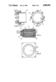
- FIG. 1 is a longitudinal section of an embodiment of the electronically commutated, collectorless direct-current motor in accordance with the invention
- FIG. 2 is a section of a plastic body with eyehooks
- FIG. 3 is an end view of the plastic body of FIG. 2;
- FIG. 4 is a side view of the stator coil with the plastic body and the eyehooks
- FIG. 5 is a front view of a lamination shape of the external magnetic yoke.
- FIG. 1 An electronically commutated, collectorless direct-current motor 1 in accordance with the invention is shown in FIG. 1. It comprises an external magnetic yoke 2, a stator 3, a multipolar rotor 4, and two end shields 5, 6. Together with an outer casing 35, the two end shields 5, 6 form a frame 36 of the direct-current motor 1.
- a shaft 7 of the rotor 4 is connected with the end shields 5, 6 via two bearings 8, 9.
- the rotor 4 comprises a steel cylinder or a cylinder 11 built up of laminations 10 supporting a multipolar magnetic system 12 which consists of several annular magnets subdivided in the axial direction, or of embedded magnetic bars. Furthermore, a bipolar annular magnet 13 is located on the shaft 7 to permit position determination.
- the cylinder 11 consisting of the laminations 10 serves as an internal magnetic yoke.
- the stator 3 consists of a multipolar stator coil 14, a plastic body 15, several eyehooks 16, and a circuit board 17.
- the stator coil 14 has a number of phase windings 29 which are equal to a multiple of the number of poles and which are wound to form a ring circuit.
- the plastic body 15 is shown in FIGS. 2 and 3. It consists of a hollow cylinder 19 with a rim 20 which is provided on the front end.
- the rim 20 has a number of recesses 21 equal to the number of phase windings and which contain the eyehooks 16.
- the hollow cylinder 19 and the rim 20 are of one-piece construction and have an inner cylindrical surface. However, the outside diameter of the rim 20 exceeds that of the hollow cylinder 19.
- the rim 20 has outer projections 23.
- pin-shaped spacers 24 Arranged at the front end of the rim 20 between the recesses 21 are pin-shaped spacers 24. Slots 25 for receiving Hall-effect sensors 26 are located in two areas between two pairs of recesses 21 instead of the spacers 24. In these slots 25, the Hall-effect sensors 26 are protected against shock and require no adjustment.
- Each end 18 of the stator coil 14 is brought along about half the circumference of the hollow cylinder 19, then around the projections 23, through the eyehooks 16 and again along about half the circumference of the hollow cylinder in such a manner that the plastic body 15 is surrounded by the end 18 of the stator coil, thus being fixed in position.
- Each of the ends 18 of the stator coil are welded to a corresponding one of the eyehooks 16.
- Each eyehook 16 is U-shaped and consists of two legs 27, 28 of different lengths.
- the shorter leg 27 is bent outside the recess 21, thus forming a hook.
- the shorter leg 27 is bent towards the longer leg 28 and welded.
- the longer leg 28 of the eyehook 16 forms a pin for connection to an electrical socket, and extends beyond the spacers 24 by about 4 mm, so that it can be inserted into the circuit board 17 and soldered.
- the shorter leg 27 primarily serves to fix the ends 18 of the stator coil within the eyehook 16 and does not extend beyond the spacers 24.
- the stator coil 14 ends 18 of the are firmly soldered to the circuit board 17 via the eyehooks 16, with the circuit board 17 resting against the spacers 24. Furthermore, the Hall-effect sensors 26 disposed in the slots 25 are electrically connected to the circuit board 17 via wires 40 and 41 (shown in FIG. 1) which are soldered to the circuit board 17. In addition, other elements are located on the circuit board 17. Thus, for example, several connectors which are electrically connected to the corresponding eyehooks 16 are soldered to the circuit board 17 so as to protrude from the frame 36 and are accessible from the outside.
- the circuit board 17, on the other hand is firmly connected with the end shield 5 by a suitable snap connection (not shown).
- the stator coil 14 is a self-supporting drum winding (FIG. 4). It is wound on a winding support and receives its shape by a thermal treatment using self-bonding lacquer. The latter insulates the coil 14 and bonds the individual wires, thus ensuring the dimensional stability after the winding support has been removed.
- the principle of the arrangement of the phase windings is already disclosed in DE-OS 34 38 747 without the self-supporting shape of the stator coil 14 having been mentioned therein and without the electric connection of the ends of the stator coil shown therein being made in the fashion described herein above.
- the stator coil 14 has an inside radius R 1 at the first winding head 30 and an inside radius R 2 at the second winding head 31, where R 1 ⁇ R 2 .
- phase windings 29 are arranged predominantly axially and in a circle with the radius R 2 . Only in the area of the first winding head 30 does the circle formed by the phase windings decrease to the radius R 1 .
- the outside radius R.sub. 3 of the first winding head 30 is smaller than the inside radius R 2 of the second winding head 31.
- the stator coil 14 has slot-shaped free spaces 32.
- the external magnetic yoke 2 is constituted by a laminated-sheet plate.
- the lamination shape is shown in FIG. 5. It has a round cutout 34 with teeth 33.
- the electronically commutated, collectorless direct-current motor in accordance with FIG. 1 is assembled by inserting the stator coil 14, with the plastic body 14 attached thereto adjacent the first winding head 30, into the laminated-sheet plate constituting the external magnetic yoke 2 so that the slot-shaped free spaces 32 of the stator coil 14 are filled by the teeth 33 of the laminated-sheet plate.
- the stator coil 14 is inserted into the laminated-sheet plate until it projects about an equal length from each side end of the laminated-sheet plate.
- the circuit board 17 is then soldered to the eyehooks 16 and the Hall-effect sensors 26.
- the end shield 5, which has a suitable device for fixing the circuit board 17, is then slipped on the stator 3 which is formed as above.
- the rotor 4 is inserted through the stator 3 on the bearing 8 of the end shield 5 and finally, the end shield 6 with the bearing 9 is placed on the rotor 4.
- the Hall-effect sensors 26 are then arranged a region adjacent the surface of the annular magnet 13.
Landscapes
- Engineering & Computer Science (AREA)
- Power Engineering (AREA)
- Insulation, Fastening Of Motor, Generator Windings (AREA)
- Brushless Motors (AREA)
- Storing, Repeated Paying-Out, And Re-Storing Of Elongated Articles (AREA)
- Primary Cells (AREA)
- Dc Machiner (AREA)
- Adhesives Or Adhesive Processes (AREA)
- Inert Electrodes (AREA)
- Polyesters Or Polycarbonates (AREA)
- Iron Core Of Rotating Electric Machines (AREA)
- Developing Agents For Electrophotography (AREA)
Applications Claiming Priority (2)
| Application Number | Priority Date | Filing Date | Title |
|---|---|---|---|
| DE19873710659 DE3710659A1 (de) | 1987-03-31 | 1987-03-31 | Elektronisch kommutierter, kollektorloser gleichstrommotor |
| DE3710659 | 1987-03-31 |
Publications (1)
| Publication Number | Publication Date |
|---|---|
| US4900968A true US4900968A (en) | 1990-02-13 |
Family
ID=6324447
Family Applications (1)
| Application Number | Title | Priority Date | Filing Date |
|---|---|---|---|
| US07/175,497 Expired - Lifetime US4900968A (en) | 1987-03-31 | 1988-03-30 | Electronically commutated collectorless direct-current motor |
Country Status (7)
| Country | Link |
|---|---|
| US (1) | US4900968A (es) |
| EP (1) | EP0285048B2 (es) |
| JP (1) | JPH01255465A (es) |
| AT (1) | ATE99466T1 (es) |
| CA (1) | CA1290381C (es) |
| DE (2) | DE3710659A1 (es) |
| ES (1) | ES2049733T5 (es) |
Cited By (15)
| Publication number | Priority date | Publication date | Assignee | Title |
|---|---|---|---|---|
| US5157293A (en) * | 1990-09-21 | 1992-10-20 | Ecia | Electric motor with electronic commutation of complex structure |
| US5283485A (en) * | 1990-11-27 | 1994-02-01 | Bayerische Motoren Werke Ag | Small-size motor and a process for manufacture and use thereof |
| US5394043A (en) * | 1993-06-29 | 1995-02-28 | American Precision Industries Inc. | High speed brushless motor |
| US5672927A (en) * | 1995-06-15 | 1997-09-30 | Quantum Corporation | Motor with overmold coil support |
| US5739603A (en) * | 1995-09-04 | 1998-04-14 | Ecia-Equipement Et Composants Pour L'industrie Automobile | Electrical connecting element for electric motor and electric motor equipped with this element |
| US6104113A (en) * | 1998-05-14 | 2000-08-15 | General Electric Company | Coil assembly for sensorless rotor angular position control of single phase permanent magnet motor |
| EP0982483A3 (de) * | 1998-08-25 | 2000-10-25 | Mannesmann VDO Aktiengesellschaft | Antriebseinrichtung |
| US6229244B1 (en) * | 1998-02-07 | 2001-05-08 | Robert Bosch Gmbh | Synchronous machine, in particular generator for a motor vehicle |
| US6538403B2 (en) | 2000-01-07 | 2003-03-25 | Black & Decker Inc. | Brushless DC motor sensor control system and method |
| US6538356B1 (en) * | 2000-06-28 | 2003-03-25 | Robert M. Jones | Electric machine using composite blade structure |
| US20030222516A1 (en) * | 2000-01-07 | 2003-12-04 | Cleanthous Aris C. | Brushless dc motor |
| US20050035674A1 (en) * | 2003-08-15 | 2005-02-17 | Brown Fred A. | Electric motor stator current controller |
| US7058291B2 (en) | 2000-01-07 | 2006-06-06 | Black & Decker Inc. | Brushless DC motor |
| US20060232143A1 (en) * | 2005-04-15 | 2006-10-19 | Delaware Capital Formation | Over molded stator |
| US20220247258A1 (en) * | 2021-02-02 | 2022-08-04 | Black & Decker Inc. | Canned brushless motor |
Families Citing this family (2)
| Publication number | Priority date | Publication date | Assignee | Title |
|---|---|---|---|---|
| DE3817423A1 (de) * | 1988-05-21 | 1989-11-23 | Standard Elektrik Lorenz Ag | Vorrichtung und verfahren zur steuerung von buerstenlosen 4-straengigen gleichstrommotoren |
| DE19748150B4 (de) | 1997-10-31 | 2006-02-23 | Minebea Co., Ltd. | Spindelmotor mit Kontaktierung |
Citations (6)
| Publication number | Priority date | Publication date | Assignee | Title |
|---|---|---|---|---|
| US3644765A (en) * | 1969-03-25 | 1972-02-22 | Philips Corp | Commutatorless direct current motor |
| US4529900A (en) * | 1978-07-29 | 1985-07-16 | Sony Corporation | Brushless motor |
| DE3438747A1 (de) * | 1984-10-23 | 1986-04-24 | Standard Elektrik Lorenz Ag, 7000 Stuttgart | Elektronisch kommutierter, kollektorloser gleichstrommotor |
| US4656378A (en) * | 1985-11-12 | 1987-04-07 | Amp Incorporated | Motor stator and connector for making connections to stator windings |
| US4682065A (en) * | 1985-11-13 | 1987-07-21 | Nidec-Torin Corporation | Molded plastic motor housing with integral stator mounting and shaft journalling projection |
| US4728836A (en) * | 1986-02-17 | 1988-03-01 | Papst-Motoren Gmbh & Co. Kg | Strain-relief housing for strand connectors of small electric motors |
Family Cites Families (5)
| Publication number | Priority date | Publication date | Assignee | Title |
|---|---|---|---|---|
| GB1522863A (en) * | 1975-02-05 | 1978-08-31 | Amp Inc | Electrical connectors |
| US4074157A (en) * | 1976-10-04 | 1978-02-14 | Synchro-Start Products, Inc. | Permanent magnet A.C. signal generator |
| DE3229458A1 (de) * | 1982-08-06 | 1984-02-09 | Ryoji Nerima Tokyo Minegishi | Geblaese mit motor |
| JPS59213264A (ja) * | 1983-05-14 | 1984-12-03 | Sony Corp | 端子基板付モ−タの組立方法 |
| EP0150070A3 (de) * | 1984-01-19 | 1986-06-04 | Papst-Motoren GmbH & Co. KG | Kollektorloser Gleichstommotor mit eisenloser Statorwicklung |
-
1987
- 1987-03-31 DE DE19873710659 patent/DE3710659A1/de not_active Withdrawn
-
1988
- 1988-03-26 EP EP88104923A patent/EP0285048B2/de not_active Expired - Lifetime
- 1988-03-26 AT AT88104923T patent/ATE99466T1/de not_active IP Right Cessation
- 1988-03-26 ES ES88104923T patent/ES2049733T5/es not_active Expired - Lifetime
- 1988-03-26 DE DE88104923T patent/DE3886575D1/de not_active Expired - Lifetime
- 1988-03-28 CA CA000562669A patent/CA1290381C/en not_active Expired - Lifetime
- 1988-03-30 JP JP63074839A patent/JPH01255465A/ja active Pending
- 1988-03-30 US US07/175,497 patent/US4900968A/en not_active Expired - Lifetime
Patent Citations (6)
| Publication number | Priority date | Publication date | Assignee | Title |
|---|---|---|---|---|
| US3644765A (en) * | 1969-03-25 | 1972-02-22 | Philips Corp | Commutatorless direct current motor |
| US4529900A (en) * | 1978-07-29 | 1985-07-16 | Sony Corporation | Brushless motor |
| DE3438747A1 (de) * | 1984-10-23 | 1986-04-24 | Standard Elektrik Lorenz Ag, 7000 Stuttgart | Elektronisch kommutierter, kollektorloser gleichstrommotor |
| US4656378A (en) * | 1985-11-12 | 1987-04-07 | Amp Incorporated | Motor stator and connector for making connections to stator windings |
| US4682065A (en) * | 1985-11-13 | 1987-07-21 | Nidec-Torin Corporation | Molded plastic motor housing with integral stator mounting and shaft journalling projection |
| US4728836A (en) * | 1986-02-17 | 1988-03-01 | Papst-Motoren Gmbh & Co. Kg | Strain-relief housing for strand connectors of small electric motors |
Cited By (23)
| Publication number | Priority date | Publication date | Assignee | Title |
|---|---|---|---|---|
| US5157293A (en) * | 1990-09-21 | 1992-10-20 | Ecia | Electric motor with electronic commutation of complex structure |
| US5283485A (en) * | 1990-11-27 | 1994-02-01 | Bayerische Motoren Werke Ag | Small-size motor and a process for manufacture and use thereof |
| US5394043A (en) * | 1993-06-29 | 1995-02-28 | American Precision Industries Inc. | High speed brushless motor |
| US5672927A (en) * | 1995-06-15 | 1997-09-30 | Quantum Corporation | Motor with overmold coil support |
| US5739603A (en) * | 1995-09-04 | 1998-04-14 | Ecia-Equipement Et Composants Pour L'industrie Automobile | Electrical connecting element for electric motor and electric motor equipped with this element |
| US6229244B1 (en) * | 1998-02-07 | 2001-05-08 | Robert Bosch Gmbh | Synchronous machine, in particular generator for a motor vehicle |
| US6104113A (en) * | 1998-05-14 | 2000-08-15 | General Electric Company | Coil assembly for sensorless rotor angular position control of single phase permanent magnet motor |
| EP0982483A3 (de) * | 1998-08-25 | 2000-10-25 | Mannesmann VDO Aktiengesellschaft | Antriebseinrichtung |
| US20030222516A1 (en) * | 2000-01-07 | 2003-12-04 | Cleanthous Aris C. | Brushless dc motor |
| US6538403B2 (en) | 2000-01-07 | 2003-03-25 | Black & Decker Inc. | Brushless DC motor sensor control system and method |
| US6975050B2 (en) | 2000-01-07 | 2005-12-13 | Black & Decker Inc. | Brushless DC motor |
| US7058291B2 (en) | 2000-01-07 | 2006-06-06 | Black & Decker Inc. | Brushless DC motor |
| US6538356B1 (en) * | 2000-06-28 | 2003-03-25 | Robert M. Jones | Electric machine using composite blade structure |
| US20050035674A1 (en) * | 2003-08-15 | 2005-02-17 | Brown Fred A. | Electric motor stator current controller |
| US6876110B2 (en) * | 2003-08-15 | 2005-04-05 | Comair Rotron, Inc. | Electric motor stator current controller |
| US20060232143A1 (en) * | 2005-04-15 | 2006-10-19 | Delaware Capital Formation | Over molded stator |
| US20080143203A1 (en) * | 2005-04-15 | 2008-06-19 | Purvines Stephen H | Over molded stator |
| US20220247258A1 (en) * | 2021-02-02 | 2022-08-04 | Black & Decker Inc. | Canned brushless motor |
| US11837935B2 (en) * | 2021-02-02 | 2023-12-05 | Black & Decker, Inc. | Canned brushless motor |
| US11855521B2 (en) | 2021-02-02 | 2023-12-26 | Black & Decker, Inc. | Brushless DC motor for a body-grip power tool |
| US11870316B2 (en) | 2021-02-02 | 2024-01-09 | Black & Decker, Inc. | Brushless motor including a nested bearing bridge |
| US11876424B2 (en) | 2021-02-02 | 2024-01-16 | Black & Decker Inc. | Compact brushless motor including in-line terminals |
| US11955863B2 (en) | 2021-02-02 | 2024-04-09 | Black & Decker Inc. | Circuit board assembly for compact brushless motor |
Also Published As
| Publication number | Publication date |
|---|---|
| ES2049733T3 (es) | 1994-05-01 |
| DE3710659A1 (de) | 1988-10-13 |
| EP0285048A3 (en) | 1989-06-14 |
| ATE99466T1 (de) | 1994-01-15 |
| ES2049733T5 (es) | 1999-01-01 |
| EP0285048A2 (de) | 1988-10-05 |
| DE3886575D1 (de) | 1994-02-10 |
| JPH01255465A (ja) | 1989-10-12 |
| CA1290381C (en) | 1991-10-08 |
| EP0285048B1 (de) | 1993-12-29 |
| EP0285048B2 (de) | 1998-10-28 |
Similar Documents
| Publication | Publication Date | Title |
|---|---|---|
| US4900968A (en) | Electronically commutated collectorless direct-current motor | |
| US10539431B2 (en) | Resolver and electric motor using same | |
| US5270604A (en) | Tandem field alternator having an improved coil and slip ring connection and method of making the same | |
| KR100386668B1 (ko) | 회전전기 | |
| US4114057A (en) | Dynamoelectric machine with inner and outer stators | |
| US4633109A (en) | Electronically commutated, collectorless direct-current motor | |
| US5298820A (en) | Miniature motor with integrated stator coil end supports | |
| KR930001543A (ko) | 전기 모터 | |
| US4829254A (en) | Electric motor with velocity indicating device | |
| US6555944B1 (en) | Deflection resisting rotor assembly | |
| JPS6339443A (ja) | モ−タの製造方法 | |
| US4914713A (en) | Rotation detection or speed pickup device for miniature d-c motor | |
| MY113886A (en) | A miniature motor | |
| US7084545B2 (en) | Electric machine and method of making an electric machine | |
| US4820951A (en) | Multiphase small size brushless DC motor | |
| US6954012B2 (en) | Permanent electric motor with a speed sensor | |
| US4341973A (en) | Armature in electrical rotary machine | |
| JPH09308163A (ja) | 電動機 | |
| JPH11215745A (ja) | 電動モータ及びステータコアの形成方法 | |
| JP6983479B2 (ja) | モータ | |
| JPH0419967Y2 (es) | ||
| US4757225A (en) | Dual stack tachometer/generator | |
| KR20230098446A (ko) | 양방향 터미널을 포함하는 모터 | |
| KR0160566B1 (ko) | 스테이터 코어의 조립체 | |
| GB2242073A (en) | Stator coil assembly for electric motors |
Legal Events
| Date | Code | Title | Description |
|---|---|---|---|
| AS | Assignment |
Owner name: STANDARD ELEKTRIK LORENZ AKTIENGESELLSCHAFT, LOREN Free format text: ASSIGNMENT OF ASSIGNORS INTEREST.;ASSIGNOR:FEIGEL, JOSEF;REEL/FRAME:004856/0299 Effective date: 19880318 Owner name: STANDARD ELEKTRIK LORENZ AKTIENGESELLSCHAFT,GERMAN Free format text: ASSIGNMENT OF ASSIGNORS INTEREST;ASSIGNOR:FEIGEL, JOSEF;REEL/FRAME:004856/0299 Effective date: 19880318 |
|
| STCF | Information on status: patent grant |
Free format text: PATENTED CASE |
|
| FEPP | Fee payment procedure |
Free format text: PAYOR NUMBER ASSIGNED (ORIGINAL EVENT CODE: ASPN); ENTITY STATUS OF PATENT OWNER: LARGE ENTITY |
|
| FPAY | Fee payment |
Year of fee payment: 4 |
|
| FEPP | Fee payment procedure |
Free format text: PAYER NUMBER DE-ASSIGNED (ORIGINAL EVENT CODE: RMPN); ENTITY STATUS OF PATENT OWNER: LARGE ENTITY Free format text: PAYOR NUMBER ASSIGNED (ORIGINAL EVENT CODE: ASPN); ENTITY STATUS OF PATENT OWNER: LARGE ENTITY |
|
| FPAY | Fee payment |
Year of fee payment: 8 |
|
| FPAY | Fee payment |
Year of fee payment: 12 |