US4900920A - Device for and method of measuring minute elongations by means of light wave conductor sensors - Google Patents
Device for and method of measuring minute elongations by means of light wave conductor sensors Download PDFInfo
- Publication number
- US4900920A US4900920A US07/116,032 US11603287A US4900920A US 4900920 A US4900920 A US 4900920A US 11603287 A US11603287 A US 11603287A US 4900920 A US4900920 A US 4900920A
- Authority
- US
- United States
- Prior art keywords
- light wave
- light
- wave conductor
- lwc
- conductor
- Prior art date
- Legal status (The legal status is an assumption and is not a legal conclusion. Google has not performed a legal analysis and makes no representation as to the accuracy of the status listed.)
- Expired - Fee Related
Links
- 239000004020 conductor Substances 0.000 title claims abstract description 33
- 238000000034 method Methods 0.000 title claims description 11
- 230000010287 polarization Effects 0.000 claims abstract description 15
- 230000008859 change Effects 0.000 claims description 18
- 238000011156 evaluation Methods 0.000 claims description 11
- 230000003287 optical effect Effects 0.000 claims description 10
- 238000012544 monitoring process Methods 0.000 claims description 7
- 230000005693 optoelectronics Effects 0.000 claims description 7
- 239000000835 fiber Substances 0.000 claims description 6
- 229920002994 synthetic fiber Polymers 0.000 claims description 4
- 150000001875 compounds Chemical class 0.000 claims description 3
- 238000005259 measurement Methods 0.000 claims description 3
- 230000008878 coupling Effects 0.000 claims description 2
- 238000010168 coupling process Methods 0.000 claims description 2
- 238000005859 coupling reaction Methods 0.000 claims description 2
- 230000010363 phase shift Effects 0.000 claims description 2
- 239000000463 material Substances 0.000 claims 1
- 238000012545 processing Methods 0.000 claims 1
- 239000011162 core material Substances 0.000 description 7
- 238000010276 construction Methods 0.000 description 5
- 230000000694 effects Effects 0.000 description 5
- 238000005452 bending Methods 0.000 description 4
- 239000013307 optical fiber Substances 0.000 description 4
- 230000008901 benefit Effects 0.000 description 3
- 239000002184 metal Substances 0.000 description 3
- 238000013016 damping Methods 0.000 description 2
- 238000010586 diagram Methods 0.000 description 2
- 230000004048 modification Effects 0.000 description 2
- 238000012986 modification Methods 0.000 description 2
- 230000008569 process Effects 0.000 description 2
- 230000005855 radiation Effects 0.000 description 2
- 230000035945 sensitivity Effects 0.000 description 2
- 229910000831 Steel Inorganic materials 0.000 description 1
- 230000009471 action Effects 0.000 description 1
- 230000001419 dependent effect Effects 0.000 description 1
- 239000011521 glass Substances 0.000 description 1
- 239000003365 glass fiber Substances 0.000 description 1
- 238000004519 manufacturing process Methods 0.000 description 1
- 239000011513 prestressed concrete Substances 0.000 description 1
- 230000001902 propagating effect Effects 0.000 description 1
- 230000002285 radioactive effect Effects 0.000 description 1
- 239000011347 resin Substances 0.000 description 1
- 229920005989 resin Polymers 0.000 description 1
- 230000004044 response Effects 0.000 description 1
- 239000010959 steel Substances 0.000 description 1
- 238000012360 testing method Methods 0.000 description 1
- 238000004804 winding Methods 0.000 description 1
Images

Classifications
-
- G—PHYSICS
- G01—MEASURING; TESTING
- G01M—TESTING STATIC OR DYNAMIC BALANCE OF MACHINES OR STRUCTURES; TESTING OF STRUCTURES OR APPARATUS, NOT OTHERWISE PROVIDED FOR
- G01M11/00—Testing of optical apparatus; Testing structures by optical methods not otherwise provided for
- G01M11/08—Testing mechanical properties
- G01M11/083—Testing mechanical properties by using an optical fiber in contact with the device under test [DUT]
- G01M11/086—Details about the embedment of the optical fiber within the DUT
-
- G—PHYSICS
- G01—MEASURING; TESTING
- G01B—MEASURING LENGTH, THICKNESS OR SIMILAR LINEAR DIMENSIONS; MEASURING ANGLES; MEASURING AREAS; MEASURING IRREGULARITIES OF SURFACES OR CONTOURS
- G01B11/00—Measuring arrangements characterised by the use of optical techniques
- G01B11/16—Measuring arrangements characterised by the use of optical techniques for measuring the deformation in a solid, e.g. optical strain gauge
- G01B11/18—Measuring arrangements characterised by the use of optical techniques for measuring the deformation in a solid, e.g. optical strain gauge using photoelastic elements
-
- G—PHYSICS
- G01—MEASURING; TESTING
- G01L—MEASURING FORCE, STRESS, TORQUE, WORK, MECHANICAL POWER, MECHANICAL EFFICIENCY, OR FLUID PRESSURE
- G01L1/00—Measuring force or stress, in general
- G01L1/24—Measuring force or stress, in general by measuring variations of optical properties of material when it is stressed, e.g. by photoelastic stress analysis using infrared, visible light, ultraviolet
- G01L1/242—Measuring force or stress, in general by measuring variations of optical properties of material when it is stressed, e.g. by photoelastic stress analysis using infrared, visible light, ultraviolet the material being an optical fibre
Definitions
- the present invention relates to a device for measuring minute elongations by means of a light wave conductor-sensor and to an arrangement of such a device or structural parts whose elongations are to be monitored.
- Light wave conductors which term is equivalent to "sheathed optical fibers" have been already formed into and installed in various sensors.
- LWC-sensors for mechanical forces (such as tension-, stress-, or compression-, bending- and torsional forces), which make themselves apparent through changes in length (such as elongation, compressing strain or buckling, bending and twisting stress). The indication of such changes in length is the corresponding change in the light damping.
- a prior art LWC-sensor for tension forces and its application for monitoring a bridge structure of prestressed concrete is described in German application DE-C2-33 05 234.
- a light wave conductor is embedded in a tension proof wire of a fiber reinforced resin structure so that the wire can be monitored as to its tension, breakage or bending.
- the LWC is enveloped in layer of synthetic material of a non-homogeneous structure; the LWC, the intermediate layer and the wire are mechanically firmly connected one to each other over the entire length thereof and the LWC is provided on both ends thereof with connectors for a light passage testing apparatus.
- the sensivity of this LWC tension sensor is further increased by winding at least one coil of a metal wire (steel wire) or of a glass fiber around the LWC to provide the non-homogeneous intermediate layer (DE-A1-35 26 966).
- LWC sensors for small radioactive radiation doses whereby the light damping is an indication of the dose
- LWC-sensors for the electric current intensity whereby the Faraday effect is utilized as an indicator.
- known is an optoelectronic current converter for measuring current in a high voltage cable which operates with Faraday effect in a monomode-LWC (Z. etz. volume 106 1985, 1160). Due to the Faraday effect the polarization plane or linear polarized light propagating (in the monomode-LWC) in the direction of magnetic field lines is rotated by the action of the applied magnetic field.
- the LWC-sensor is coupled at one end thereof to a polarizer and a light source and at the other end thereof to an analyzer and an evaluation electronic.
- the present invention belongs to the group of LWC-sensors for mechanical forces and its objective is to provide such a LWC-sensor which is capable of sensing the minimum elongations and is designed such that in connection with opto-electronic light emitting and light receiving devices detects deformations in the range of microns.
- Another objective of this invention is to provide an arrangement of such LWC-sensors which is applicable for measuring elongations in structural parts.
- one feature of this invention resides, in a device for measuring minute elongations by means of a light wave conductor, in the provision of a polarization preserving, double refracting monomode light wave conductor which in order to create a LWC-phase sensor, is series connected at one end thereof with a polarizer and a light coupling and at the other end with an analyzer.
- a light beam from a light source is conducted into the polarizer and introduced through the coupler as a linear polarized light whose phase difference undergoes changes in response to changes in length of the light wave conductor.
- the light wave conductor in the phase sensor of this invention has a particular structure for achieving a configuration double refraction.
- the latter effect is achieved by enclosing a light wave conducting core (an optical fiber) into an elliptical sheathing or jacket which causes permanent anisotropic mechanical stress in the fiber.
- a light wave conducting core an optical fiber
- a round light wave conducting core is enclosed in an optically anisotropic jacket in such a manner that the refraction index of the jacket is different in two mutually perpendicular axes.
- the light emitter is a laser or a laser diode and the light receiver is a photodiode;
- the electronic evaluation circuit has an input including a computer connected to the photodiode and an output part including a control for the laser.
- the LWC-phase sensor is permanently and mechanically rigidly connected to the construction part or in the case of fiber reinforced structural parts of synthetic material is integrally embedded in the laminated structures. In this manner load deflections particularly of component parts for e.g. of an airplane, a machine tool or a bridge construction can be continuously monitored.
- LWC-phase sensors of this invention are arranged in those zones of component parts of an airplane which are susceptible to breakage and are connected by a light wave conducting cable to a remote optoelectronic light emitter and light receiver and its electronic evaluation apparatus.
- the method of measuring minute elongations of a light wave conductor thus resides in the steps of introducing a linear polarized light into a polarization preserving, doubly refracing light wave conductor in which the passing light wave is shifted about a phase difference d, detecting a change of the phase difference caused by a change in length of LWC-sensor by an optoelectric evaluation apparatus which evaluates the change as a measure of the geometric elongation.
- the coupler introduces the polarized light at an angle of 45° relative to the optical axis of the light wave conductor.
- a substantial advantage of the invention is the fact that the LWC-phase sensor in cooperation with the optoelectronic light emitting, light receiving and electrical signals evaluating devices results in a highly sensitive device capable of detecting minimum elongations so that deformations in the micron range can be detected.
- the invention is suitable particularly in measuring minute elongations such as load deflections of supporting struts or beams.
- FIG. 1 is a schematic representation of a measuring device including a light wave conductor-phase sensor of this invention
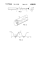
- FIG. 2 is a perspective view of a cut-away part of a sheathed monomode-light wave conductor having a double refracting configuration
- FIG. 3 is a plot diagram of a light wave signal at the output of the phase-sensor of this invention.
- FIG. 4 is a block circuit diagram of an elongation monitoring system employing a LWC-phase sensor of this invention.
- FIG. 5 is a perspective view of an arrangement employing a plurality of LWC-phase sensors to monitor tail of an airplane.
- reference numeral 1 indicates a light emitter (laser or a laser diode)
- 2 refers to a polarizer
- 3 to a polarized light coupler
- 4 denotes a polarization preserving, doubly refracting monomode-LWC
- 4a indicates the light wave conductor 4 stripped of its sheath or jacket (an optical fiber)
- 5 refers to a polarized light analyzer
- 6 indicates a LWC-phase sensor
- 7 denotes a light receiver (a photodiode)
- 8 refers to an indicator
- 9 to a computer (a data-processor)
- 10 to a control circuit for the light emitter
- 11 indicates an evaluation device
- 12 indicates a monomode light wave conducting connection cable
- 13 refers to a tail of an airplane provided with a monitoring arrangement including a plurality of LWC-phase sensors.
- the device of this invention includes a polarization preserving, doubly refracting monomode light wave conductor 4 as an element for measuring minute elongations.
- the monomode LWC of this type has for example a round light conducting core provided with an elliptical sheathing or jacket which introduces a permanent anisotropic mechanical stress into the core.
- the input end of the LWC 4 is coupled via a coupler 3 to a polarizer 2 and the other end to an analyzer 5 such that the elements 2 through 5 form an LWC-phase sensor 6.
- a light emitter 1 is coupled to the input end of the phase sensor 6 and a light receiver 7 to the output end.
- a monomode light wave conduit or cable 12 serves as a connector between the phase sensor 6 and the light emitter and receiver.
- the light emitter 1 is a laser or a laser diode and light receiver 7 is a photodiode.
- An evaluation circuit 11 which is connected to the output of photodiode 7 has at its input a computer 9 and at its output a control device 10 for the light emitter.
- the optical elongation sensor utilizes a special type of light wave conductor, namely a polarization preserving, doubly refracting monomode LWC.
- a special type of LWC In manufacturing such a special type of LWC, an elliptical jacket is applied on a round core (an optical fiber) such as to achieve a permanent anisotropic (direction dependent) mechanical stress.
- the light wave conductor becomes doubly refracting, that means the conducted light wave is split into two component waves.
- the two main axes of the ellipsis correspond to the optical axes directed perpendicularly to the LWC-axis and being fixedly oriented in space and having respective refraction indices n o and n ao .
- the optical anisotropy and double refraction mean that the speed of the light propagation depends in characteristic manner on the refraction index of the glass.
- the optical axes characterize the directions of polarization for which the differences of refraction indices n 0 -n ao is maximum.
- Linear polarized light during the passage through the light wave conductor is shifted by a phase difference d.
- the propagation of linear polarized light in the doubly refracting LWC having the beforedescribed position of optical axes can be described as an incident wave represented through the superposition of two component waves whose polarization directions coincide with respective optical axes. After the passage through the LWC the two component waves are again superposed whereby the phase difference d is to be considered. Accordingly, different forms of polarization (linear, elliptical, circular) of the light transmitted through the LWC occur and an optoelectronic analysis of the polarization state permits the determination of the phase difference d.
- the linear polarized light is coupled at 45° relative to the optical axis of the LWC at the input of the latter then at the output of the LWC a signal having intensity I is received behind a polarization filter.
- the intensity of the signal can be expressed by the function
- I o is the intensity of the optical signal at the input of the LWC phase sensor and d is the phase difference according to the formula
- ⁇ the wavelength of the coupled in light
- FIG. 3 illustrates the graphical representation of the function I.
- K is optomechanical constant of the LWC.
- measurements of the minute elongations are to be carried out in such a manner that linear polarized light is coupled into the polarization preserving and in addition doubly refracting monomode-LWC 4 wherein during the passage the light wave is phase shifted by a phase difference d and, in the case of a change in length of the monomode-LWC 4 the resulting phase difference change ⁇ d is detected by the optoelectrical light receiver 7 and evaluated in the evaluation device 11 to provide a measure for the geometric change in length.
- the LWC-phase sensor of this invention is particularly suitable for measuring minute elongations such as load bending of carrying or supporting members.
- the measuring method of this invention will be explained in detail.
- the measured radiation power and the applied mechanical stress which can be scaled according to Hook's law in length changes and which can be maintained with very simply measuring technique.
- the measuring speed at stable operation of the light source depends on the speed of the employed electronic circuit only.
- the aforementioned measuring range ascertained during the first application can be doubled when the measuring light is splitted by means of a grid into channels. In this way it is made possible to determine with simple arithmetic the phase difference d modulo 2 ⁇ (modul of congruence) with substantially the same accuracy.
- the interval 2 ⁇ can be exceeded.
- the measuring speed will be will be lowered but inasmuch as the number of phase shifts by 2 ⁇ is ascertained in both directions, that means with correct sign + or -, it is possible to determine also large changes in length through the electronic counting process.
- the field of application of the LWC-phase sensor includes a continuous monitoring of critical deformations and structural damages of structural parts of metal and fiber reinforced compounds.
- the LWC-sensor is mechanically firmly and permanently connected with the structural part to be monitored.
- structural parts made of fiber reinforced synthetic materials it is also possible to embed the sensor in the laminate.
- the LWC-sensors of this invention are suitable particularly for monitoring the load bending of structural parts of airplanes, machine tools or bridge constructions so that the risk of an operational failure is reduced.
- FIG. 5 illustrates a plurality of LWC-phase sensors 6 arranged in the zones of an airplane which are susceptible to breakage, for example at different locations of the tail unit 13 of an airplane wherefrom a monomode light wave conducting connection cable 12 connects the sensors to an optoelectronic transmitter 1 and receiver 7 which together with the electronic evaluation circuit 7 are arranged in a control space within the airplane.
Landscapes
- Physics & Mathematics (AREA)
- General Physics & Mathematics (AREA)
- Chemical & Material Sciences (AREA)
- Analytical Chemistry (AREA)
- Length Measuring Devices By Optical Means (AREA)
- Light Guides In General And Applications Therefor (AREA)
Abstract
A device for measuring minute elongations of a light wave conductor is constructed as a light wave conductor-type sensing unit assembled of a series connection of a polarizer, a light coupler, a single polarization preserving, doubly refracting monomode light wave conductor enclosed in an elliptical sheathing and an analyzer. A light beam emitted from a laser diode is coupled via a light wave conducting correction cable to the polarizer and upon passage through the sensing unit is coupled via the light wave conducting connection cable to an optoelectric receiver and the electrical signals are evaluated in an electronic circuit. Changes in phase difference of the exiting light wave resulting from the minute changes in length of the light wave conductor are evaluated and scaled as geometric length units.
Description
The present invention relates to a device for measuring minute elongations by means of a light wave conductor-sensor and to an arrangement of such a device or structural parts whose elongations are to be monitored.
Light wave conductors (LWC), which term is equivalent to "sheathed optical fibers" have been already formed into and installed in various sensors. One of the most abundant groups of such sensors includes LWC-sensors for mechanical forces (such as tension-, stress-, or compression-, bending- and torsional forces), which make themselves apparent through changes in length (such as elongation, compressing strain or buckling, bending and twisting stress). The indication of such changes in length is the corresponding change in the light damping.
A prior art LWC-sensor for tension forces and its application for monitoring a bridge structure of prestressed concrete is described in German application DE-C2-33 05 234. In this known embodiment a light wave conductor is embedded in a tension proof wire of a fiber reinforced resin structure so that the wire can be monitored as to its tension, breakage or bending. For this purpose the LWC is enveloped in layer of synthetic material of a non-homogeneous structure; the LWC, the intermediate layer and the wire are mechanically firmly connected one to each other over the entire length thereof and the LWC is provided on both ends thereof with connectors for a light passage testing apparatus. The sensivity of this LWC tension sensor is further increased by winding at least one coil of a metal wire (steel wire) or of a glass fiber around the LWC to provide the non-homogeneous intermediate layer (DE-A1-35 26 966).
From the multitude of the different known LWC sensors only the following types will be mentioned; there are LWC sensors for small radioactive radiation doses whereby the light damping is an indication of the dose (DE-U1-82 18 823); and LWC-sensors for the electric current intensity whereby the Faraday effect is utilized as an indicator. For example, known is an optoelectronic current converter for measuring current in a high voltage cable which operates with Faraday effect in a monomode-LWC (Z. etz. volume 106 1985, 1160). Due to the Faraday effect the polarization plane or linear polarized light propagating (in the monomode-LWC) in the direction of magnetic field lines is rotated by the action of the applied magnetic field. To determine from the Faraday effect the current values, the LWC-sensor is coupled at one end thereof to a polarizer and a light source and at the other end thereof to an analyzer and an evaluation electronic.
The present invention belongs to the group of LWC-sensors for mechanical forces and its objective is to provide such a LWC-sensor which is capable of sensing the minimum elongations and is designed such that in connection with opto-electronic light emitting and light receiving devices detects deformations in the range of microns.
Another objective of this invention is to provide an arrangement of such LWC-sensors which is applicable for measuring elongations in structural parts.
In keeping with these objects and others which will become apparent hereafter, one feature of this invention resides, in a device for measuring minute elongations by means of a light wave conductor, in the provision of a polarization preserving, double refracting monomode light wave conductor which in order to create a LWC-phase sensor, is series connected at one end thereof with a polarizer and a light coupling and at the other end with an analyzer. A light beam from a light source is conducted into the polarizer and introduced through the coupler as a linear polarized light whose phase difference undergoes changes in response to changes in length of the light wave conductor. These phase difference changes are detected in a light receiver and evaluated in an electronic evaluation circuit.
The light wave conductor in the phase sensor of this invention has a particular structure for achieving a configuration double refraction. For example, the latter effect is achieved by enclosing a light wave conducting core (an optical fiber) into an elliptical sheathing or jacket which causes permanent anisotropic mechanical stress in the fiber. Alternatively, it is possible to enclose a light wave conductive core of elliptical cross-section into a round sheathing or jacket.
In still another modification, a round light wave conducting core is enclosed in an optically anisotropic jacket in such a manner that the refraction index of the jacket is different in two mutually perpendicular axes.
In a preferred embodiment of this invention, the light emitter is a laser or a laser diode and the light receiver is a photodiode; the electronic evaluation circuit has an input including a computer connected to the photodiode and an output part including a control for the laser.
In order to create an arrangement for continuous monitoring critical deformations and structural damages of construction parts of metal and synthetic compounds, the LWC-phase sensor is permanently and mechanically rigidly connected to the construction part or in the case of fiber reinforced structural parts of synthetic material is integrally embedded in the laminated structures. In this manner load deflections particularly of component parts for e.g. of an airplane, a machine tool or a bridge construction can be continuously monitored.
In another preferred embodiment of a plurality of LWC-phase sensors of this invention are arranged in those zones of component parts of an airplane which are susceptible to breakage and are connected by a light wave conducting cable to a remote optoelectronic light emitter and light receiver and its electronic evaluation apparatus.
The method of measuring minute elongations of a light wave conductor thus resides in the steps of introducing a linear polarized light into a polarization preserving, doubly refracing light wave conductor in which the passing light wave is shifted about a phase difference d, detecting a change of the phase difference caused by a change in length of LWC-sensor by an optoelectric evaluation apparatus which evaluates the change as a measure of the geometric elongation. In a preferred arrangement of the LWC-sensor the coupler introduces the polarized light at an angle of 45° relative to the optical axis of the light wave conductor.
As mentioned before a substantial advantage of the invention is the fact that the LWC-phase sensor in cooperation with the optoelectronic light emitting, light receiving and electrical signals evaluating devices results in a highly sensitive device capable of detecting minimum elongations so that deformations in the micron range can be detected. As a consequence, the invention is suitable particularly in measuring minute elongations such as load deflections of supporting struts or beams.
The novel features which are considered as characteristic for the invention are set forth in particular in the appended claims. The invention itself, however, both as to its construction and its method of operation, together with additional objects and advantages thereof, will be best understood from the following description of specific embodiments when read in connection with the accompanying drawings.
FIG. 1 is a schematic representation of a measuring device including a light wave conductor-phase sensor of this invention;
FIG. 2 is a perspective view of a cut-away part of a sheathed monomode-light wave conductor having a double refracting configuration;
FIG. 3 is a plot diagram of a light wave signal at the output of the phase-sensor of this invention;
FIG. 4 is a block circuit diagram of an elongation monitoring system employing a LWC-phase sensor of this invention; and
FIG. 5 is a perspective view of an arrangement employing a plurality of LWC-phase sensors to monitor tail of an airplane.
In the drawings, reference numeral 1 indicates a light emitter (laser or a laser diode), 2 refers to a polarizer, 3 to a polarized light coupler, 4 denotes a polarization preserving, doubly refracting monomode-LWC, 4a indicates the light wave conductor 4 stripped of its sheath or jacket (an optical fiber), 5 refers to a polarized light analyzer, 6 indicates a LWC-phase sensor, 7 denotes a light receiver (a photodiode), 8 refers to an indicator, 9 to a computer (a data-processor), 10 to a control circuit for the light emitter, 11 indicates an evaluation device, 12 indicates a monomode light wave conducting connection cable, and 13 refers to a tail of an airplane provided with a monitoring arrangement including a plurality of LWC-phase sensors.
As shown in FIGS. 1 and 4, the device of this invention includes a polarization preserving, doubly refracting monomode light wave conductor 4 as an element for measuring minute elongations. The monomode LWC of this type has for example a round light conducting core provided with an elliptical sheathing or jacket which introduces a permanent anisotropic mechanical stress into the core. The input end of the LWC 4 is coupled via a coupler 3 to a polarizer 2 and the other end to an analyzer 5 such that the elements 2 through 5 form an LWC-phase sensor 6. A light emitter 1 is coupled to the input end of the phase sensor 6 and a light receiver 7 to the output end. A monomode light wave conduit or cable 12 serves as a connector between the phase sensor 6 and the light emitter and receiver.
In this example, the light emitter 1 is a laser or a laser diode and light receiver 7 is a photodiode. An evaluation circuit 11 which is connected to the output of photodiode 7 has at its input a computer 9 and at its output a control device 10 for the light emitter.
The operation of the LWC-phase sensor of this invention will be explained with reference to FIGS. 2 and 3. As mentioned before, the optical elongation sensor utilizes a special type of light wave conductor, namely a polarization preserving, doubly refracting monomode LWC. In manufacturing such a special type of LWC, an elliptical jacket is applied on a round core (an optical fiber) such as to achieve a permanent anisotropic (direction dependent) mechanical stress.
Due to the anisotropic stress the light wave conductor becomes doubly refracting, that means the conducted light wave is split into two component waves. The two main axes of the ellipsis correspond to the optical axes directed perpendicularly to the LWC-axis and being fixedly oriented in space and having respective refraction indices no and nao. The optical anisotropy and double refraction mean that the speed of the light propagation depends in characteristic manner on the refraction index of the glass. The optical axes characterize the directions of polarization for which the differences of refraction indices n0 -nao is maximum.
Linear polarized light during the passage through the light wave conductor is shifted by a phase difference d. The propagation of linear polarized light in the doubly refracting LWC having the beforedescribed position of optical axes can be described as an incident wave represented through the superposition of two component waves whose polarization directions coincide with respective optical axes. After the passage through the LWC the two component waves are again superposed whereby the phase difference d is to be considered. Accordingly, different forms of polarization (linear, elliptical, circular) of the light transmitted through the LWC occur and an optoelectronic analysis of the polarization state permits the determination of the phase difference d.
If the linear polarized light is coupled at 45° relative to the optical axis of the LWC at the input of the latter then at the output of the LWC a signal having intensity I is received behind a polarization filter. The intensity of the signal can be expressed by the function
I=I.sub.o (1+cos d)
wherein, Io is the intensity of the optical signal at the input of the LWC phase sensor and d is the phase difference according to the formula
d=(2/λ)·(n.sub.o -n.sub.ao)·l.sub.o
with the refraction indices difference no -nao =c·s, and
λ=the wavelength of the coupled in light,
c=Brewster constant of the core material,
s=mechanical stress, and
lo =length of the LWC.
FIG. 3 illustrates the graphical representation of the function I.
Inasmuch as the refraction indeces difference depends, as shown above, on the mechanical stress only, a change of the phase difference Δd depends only on the change of the length Δlo according to the formula
Δd=(2π/λ)·K·Δl.sub.o
wherein K=is optomechanical constant of the LWC.
Consequently it results that from the phase difference change of the light coupled into the LWC-phase sensor the length change of the light wave conductor LWC can be directly determined.
Accordingly, measurements of the minute elongations (changes in length) are to be carried out in such a manner that linear polarized light is coupled into the polarization preserving and in addition doubly refracting monomode-LWC 4 wherein during the passage the light wave is phase shifted by a phase difference d and, in the case of a change in length of the monomode-LWC 4 the resulting phase difference change Δd is detected by the optoelectrical light receiver 7 and evaluated in the evaluation device 11 to provide a measure for the geometric change in length.
Preliminary measurements had shown that a phase difference change Δd=π is caused by a length change of about 1.5 microns. Consequently, the LWC-phase sensor of this invention is particularly suitable for measuring minute elongations such as load bending of carrying or supporting members.
With reference to FIG. 3 the measuring method of this invention will be explained in detail. In the course of the preliminary application the sensitivity over the measuring length lo can be adjusted in such a manner that the linear range A-B on the curve I=f(d) is not exceeded. Under this condition one obtains a proportionality between the measured radiation power and the applied mechanical stress which can be scaled according to Hook's law in length changes and which can be maintained with very simply measuring technique.
In a first realization of this application a length change Δlo of about 5 microns at a measuring length lo =500 mm was sufficient for passing through the measuring range C-D. Hence, with the matching electronic it was possible to measure elongation with an indication accuracy Δlo /lo of 10-6.
The measuring speed at stable operation of the light source depends on the speed of the employed electronic circuit only.
The aforementioned measuring range ascertained during the first application can be doubled when the measuring light is splitted by means of a grid into channels. In this way it is made possible to determine with simple arithmetic the phase difference d modulo 2π (modul of congruence) with substantially the same accuracy.
Particularly when measuring dynamic processes the interval 2π can be exceeded. Of course, the measuring speed will be will be lowered but inasmuch as the number of phase shifts by 2π is ascertained in both directions, that means with correct sign + or -, it is possible to determine also large changes in length through the electronic counting process.
From the proceeding explanation it is evident that the concept of the sensor according to this invention provides a high sensitivity with a large measuring range.
The field of application of the LWC-phase sensor includes a continuous monitoring of critical deformations and structural damages of structural parts of metal and fiber reinforced compounds. For this purpose the LWC-sensor is mechanically firmly and permanently connected with the structural part to be monitored. In the case of structural parts made of fiber reinforced synthetic materials, it is also possible to embed the sensor in the laminate. The LWC-sensors of this invention are suitable particularly for monitoring the load bending of structural parts of airplanes, machine tools or bridge constructions so that the risk of an operational failure is reduced.
FIG. 5 illustrates a plurality of LWC-phase sensors 6 arranged in the zones of an airplane which are susceptible to breakage, for example at different locations of the tail unit 13 of an airplane wherefrom a monomode light wave conducting connection cable 12 connects the sensors to an optoelectronic transmitter 1 and receiver 7 which together with the electronic evaluation circuit 7 are arranged in a control space within the airplane.
While the invention has been illustrated and described as embodied in specific examples of a light wave conductor phase sensor, it is not intended to be limited to the details shown, since various modifications and structural changes may be made without departing in any way from the spirit of the present invention.
Without further analysis, the foregoing will so fully reveal the gist of the present invention that others can, by applying current knowledge, readily adapt it for various applications without omitting features that, from the standpoint of prior art, fairly constitute essential characteristics of the generic or specific aspects of this invention.
Claims (9)
1. A device for measuring minute elongations of a light wave conductor, comprising:
a light emitter;
a light wave sending unit assembled of a series arrangement of a polarizer, a light coupler, a single light wave conductor of a round cross-section enclosed in an elliptical sheathing which produces a permanent anisotropic mechanical stress in said light wave conductor to provide a polarization preserving, doubly refracting monomode light wave conductor phase sensor, and a light analyzer;
a light receiver for converting polarized light waves into electrical signals;
light wave conducting means for coupling said light emitter to said polarizer, and said light receiver to said analyzer; and
an electronic evaluating circuit for evaluating phase difference change of said electrical signals as a measure of elongation of said single light wave conductor.
2. A device as defined in claim 1, wherein said light emitter is a laser or a laser diode and said light receiver is a photo diode, and said electronic evaluating circuit includes a computer for processing said electrical signals and a control for controlling said light emitter.
3. An arrangement of at least one device according to claim 1 for continuously monitoring critical deformations and structural damages of structural parts, wherein said light wave conductor type sensing unit is permanently and mechanically rigidly secured to a structural part to be monitored, said light emitter and receiver together with said electronic evaluation circuit being arranged at a remote location and connected to said sensing unit by a light wave conducting connection cable.
4. An arrangement as defined in claim 3, wherein said component part being monitored is made of fiber reinforced laminated compound of synthetic material and said sensing unit is embedded in a laminar layer of said material.
5. An arrangement as defined in claim 3, wherein the structural part to be monitored is part of an airplane, of a machine tool or of a bridge structure.
6. An arrangement as defined in claim 3, comprising a plurality of said sensing units secured to breakage susceptible zones of an airplane and connected via said light wave conducting connection cable to said light emitter and said light receiver arranged in a control space within said airplane.
7. A method of measuring minute elongations of a light wave conductor, comprising the steps of feeding linear polarized light into a polarization preserving, doubly refracting light wave conductor wherein the light wave is shifted by a phase difference d, detecting the light wave exiting from the light wave conductor by an optoelectronic evaluation device wherein a phase difference change resulting from a change of the length of said light wave conductor is evaluated and employed as a measure for the geometric change in length.
8. A method as defined in claim 7, wherein the polarized light is fed into said light wave conductor at an angle of 45° relative to the optical axis of said light wave conductor.
9. A method as defined in claim 7, wherein the number of phase shifts by 2π is detected in both directions in order to ascertain the sign of the shifting in order to increase the range of the length measurement.
Applications Claiming Priority (2)
| Application Number | Priority Date | Filing Date | Title |
|---|---|---|---|
| DE3638345 | 1986-11-10 | ||
| DE19863638345 DE3638345A1 (en) | 1986-11-10 | 1986-11-10 | SETUP AND USE OF A WAVE GUIDE SENSOR FOR MINIMUM EXPANSION |
Publications (1)
| Publication Number | Publication Date |
|---|---|
| US4900920A true US4900920A (en) | 1990-02-13 |
Family
ID=6313611
Family Applications (1)
| Application Number | Title | Priority Date | Filing Date |
|---|---|---|---|
| US07/116,032 Expired - Fee Related US4900920A (en) | 1986-11-10 | 1987-11-02 | Device for and method of measuring minute elongations by means of light wave conductor sensors |
Country Status (3)
| Country | Link |
|---|---|
| US (1) | US4900920A (en) |
| EP (1) | EP0267381B1 (en) |
| DE (2) | DE3638345A1 (en) |
Cited By (13)
| Publication number | Priority date | Publication date | Assignee | Title |
|---|---|---|---|---|
| US5182449A (en) * | 1990-02-06 | 1993-01-26 | The Boeing Corporation | System and method for structural monitoring using optical imaging of fiber sensors |
| WO1995030926A1 (en) * | 1994-05-06 | 1995-11-16 | The University Of Sydney | Variable property light transmitting device |
| US5493406A (en) * | 1992-07-31 | 1996-02-20 | Hamamatsu Photonics K.K. | Apparatus for measuring spectral characteristics of an optical fiber component |
| WO1996018866A1 (en) * | 1994-12-16 | 1996-06-20 | Safety-One A/S | A method and device for continuous monitoring of dynamic loads |
| CN1051179C (en) * | 1995-10-28 | 2000-04-05 | 金钟-默勒有限公司 | Power feed box |
| WO2001026226A1 (en) * | 1999-10-06 | 2001-04-12 | Microsoft Corporation | Keypad having optical waveguides |
| US6542304B2 (en) | 1999-05-17 | 2003-04-01 | Toolz, Ltd. | Laser beam device with apertured reflective element |
| US6587188B2 (en) | 2000-02-02 | 2003-07-01 | Airbus Deutschland Gmbh | Method and sensor arrangement for measuring temperature and strain using an optical fiber embedded in a cover layer on a substrate |
| US20060288796A1 (en) * | 2003-08-27 | 2006-12-28 | Giazotto Alessandro R B | Method and apparatus suitable for measuring the displacement or load on an aircraft component |
| US20070006662A1 (en) * | 2003-08-27 | 2007-01-11 | Giazotto Alessandro Riccardo B | Optically measuring the dispacing or load for an aircraft component, landing gear, braking control |
| US20070032919A1 (en) * | 2003-08-27 | 2007-02-08 | Giazotto Alessandro R B | Measuring load on an aircraft component by microwave distance links |
| US8534132B1 (en) | 2010-11-19 | 2013-09-17 | Charles L. Purdy | Method for measuring tension in an anchored rod at an accessible end |
| US20230023964A1 (en) * | 2019-12-17 | 2023-01-26 | Peri Gmbh | Formwork panel for a formwork structure |
Families Citing this family (9)
| Publication number | Priority date | Publication date | Assignee | Title |
|---|---|---|---|---|
| DE4115370A1 (en) * | 1991-05-10 | 1992-11-26 | Asea Brown Boveri | Fibre=optic sensor for alternating electric fields or voltages - has piezoelectric element with attached optical fibre carrying two coherent light modes, and also fibre length variation detector |
| FR2707754B1 (en) * | 1993-07-12 | 1995-10-06 | Aerospatiale | On-board structure on space vehicle, having integrated dimensional sensors. |
| DE4344856A1 (en) * | 1993-12-29 | 1995-07-06 | Abb Research Ltd | Fiber optic transmission sensor with modulator |
| DE19705889C2 (en) * | 1997-02-15 | 1999-12-09 | Daimler Chrysler Ag | Angle of rotation sensor |
| DE19902783C2 (en) * | 1999-01-25 | 2002-11-07 | Ettemeyer Ag | measuring unit |
| US20040129868A1 (en) * | 2003-01-08 | 2004-07-08 | Siemens Vdo Automotive Corporation. | Deflection sensor |
| DE102010005665A1 (en) | 2010-01-26 | 2011-07-28 | Dr. Ing. h.c. F. Porsche Aktiengesellschaft, 70435 | System for measuring torsion between two measuring points of measuring section in e.g. lorry, has polarization analyzer attached to optical waveguide at measuring point, where point is connected with another measuring point over waveguide |
| DE102014002109A1 (en) * | 2014-02-15 | 2015-08-20 | Audi Ag | Component, component assembly and method for deformation detection of a component |
| DE102016125730A1 (en) | 2016-12-27 | 2018-06-28 | fos4X GmbH | Device and method for measuring the torsion of a measuring object |
Citations (7)
| Publication number | Priority date | Publication date | Assignee | Title |
|---|---|---|---|---|
| US4269506A (en) * | 1978-04-18 | 1981-05-26 | Max-Planck-Gesellschaft Zur Forderung Der Wissenschaften E.V. | Apparatus for measuring the influence of physical parameters on the length of a path |
| DE8212823U1 (en) * | 1982-05-04 | 1982-08-19 | Felten & Guilleaume Energietechnik GmbH, 5000 Köln | LIGHTWAVE GUIDE SENSOR FOR SMALL RADIOACTIVE RADIO CAN |
| DE3305234A1 (en) * | 1983-02-16 | 1984-08-16 | Felten & Guilleaume Energietechnik GmbH, 5000 Köln | TENSION-RESISTANT WIRE WITH AN INCLUDED FOCUS SENSOR |
| US4495411A (en) * | 1982-10-27 | 1985-01-22 | The United States Of America As Represented By The Secretary Of The Navy | Fiber optic sensors operating at DC |
| DE3526966A1 (en) * | 1984-11-14 | 1986-05-15 | Felten & Guilleaume Energietechnik GmbH, 5000 Köln | LIGHTWAVE GUIDE SENSOR FOR TOWING FORCES AND METHOD FOR THE PRODUCTION THEREOF |
| US4659923A (en) * | 1981-03-09 | 1987-04-21 | Polaroid Corporation | Fiber optic interferometer transducer |
| US4671659A (en) * | 1985-11-08 | 1987-06-09 | Martin Marietta Corporation | Fiber optic displacement sensor |
Family Cites Families (6)
| Publication number | Priority date | Publication date | Assignee | Title |
|---|---|---|---|---|
| DE2602691A1 (en) * | 1976-01-24 | 1977-07-28 | Caspers Friedhelm | Small length change measuring device - uses phase change of optical wave with change in glass fibre waveguide length to change voltage |
| US4420251A (en) * | 1980-05-05 | 1983-12-13 | Rockwell International Corporation | Optical deformation sensor |
| JPS5940202A (en) * | 1982-08-31 | 1984-03-05 | Hitachi Cable Ltd | Strain gage using optical fiber for preserving plane of polarization |
| DE3311524C2 (en) * | 1983-03-30 | 1985-11-14 | Licentia Patent-Verwaltungs-Gmbh, 6000 Frankfurt | Fiber optic sensor for force and pressure measurements as well as for monitoring and protection purposes |
| DE3415855A1 (en) * | 1984-04-28 | 1985-11-07 | Licentia Patent-Verwaltungs-Gmbh, 6000 Frankfurt | Fibre-optic measuring device for measuring a tensile stress or flexure occurring on a component |
| US4515473A (en) * | 1984-09-13 | 1985-05-07 | Geo-Centers, Inc. | Photoelastic stress sensor signal processor |
-
1986
- 1986-11-10 DE DE19863638345 patent/DE3638345A1/en not_active Withdrawn
-
1987
- 1987-08-29 EP EP87112646A patent/EP0267381B1/en not_active Expired - Lifetime
- 1987-08-29 DE DE8787112646T patent/DE3771031D1/en not_active Expired - Lifetime
- 1987-11-02 US US07/116,032 patent/US4900920A/en not_active Expired - Fee Related
Patent Citations (7)
| Publication number | Priority date | Publication date | Assignee | Title |
|---|---|---|---|---|
| US4269506A (en) * | 1978-04-18 | 1981-05-26 | Max-Planck-Gesellschaft Zur Forderung Der Wissenschaften E.V. | Apparatus for measuring the influence of physical parameters on the length of a path |
| US4659923A (en) * | 1981-03-09 | 1987-04-21 | Polaroid Corporation | Fiber optic interferometer transducer |
| DE8212823U1 (en) * | 1982-05-04 | 1982-08-19 | Felten & Guilleaume Energietechnik GmbH, 5000 Köln | LIGHTWAVE GUIDE SENSOR FOR SMALL RADIOACTIVE RADIO CAN |
| US4495411A (en) * | 1982-10-27 | 1985-01-22 | The United States Of America As Represented By The Secretary Of The Navy | Fiber optic sensors operating at DC |
| DE3305234A1 (en) * | 1983-02-16 | 1984-08-16 | Felten & Guilleaume Energietechnik GmbH, 5000 Köln | TENSION-RESISTANT WIRE WITH AN INCLUDED FOCUS SENSOR |
| DE3526966A1 (en) * | 1984-11-14 | 1986-05-15 | Felten & Guilleaume Energietechnik GmbH, 5000 Köln | LIGHTWAVE GUIDE SENSOR FOR TOWING FORCES AND METHOD FOR THE PRODUCTION THEREOF |
| US4671659A (en) * | 1985-11-08 | 1987-06-09 | Martin Marietta Corporation | Fiber optic displacement sensor |
Cited By (20)
| Publication number | Priority date | Publication date | Assignee | Title |
|---|---|---|---|---|
| US5182449A (en) * | 1990-02-06 | 1993-01-26 | The Boeing Corporation | System and method for structural monitoring using optical imaging of fiber sensors |
| US5493406A (en) * | 1992-07-31 | 1996-02-20 | Hamamatsu Photonics K.K. | Apparatus for measuring spectral characteristics of an optical fiber component |
| WO1995030926A1 (en) * | 1994-05-06 | 1995-11-16 | The University Of Sydney | Variable property light transmitting device |
| WO1996018866A1 (en) * | 1994-12-16 | 1996-06-20 | Safety-One A/S | A method and device for continuous monitoring of dynamic loads |
| AU706244B2 (en) * | 1994-12-16 | 1999-06-10 | Light Structures As | A method and device for continuous monitoring of dynamic loads |
| US5942750A (en) * | 1994-12-16 | 1999-08-24 | Safety-One As | Method and device for continuous monitoring of dynamic loads |
| CN1051179C (en) * | 1995-10-28 | 2000-04-05 | 金钟-默勒有限公司 | Power feed box |
| US20030137741A1 (en) * | 1999-05-17 | 2003-07-24 | Tacklind Christopher A. | Methods and apparatus for laser device adjustment |
| US6542304B2 (en) | 1999-05-17 | 2003-04-01 | Toolz, Ltd. | Laser beam device with apertured reflective element |
| WO2001026226A1 (en) * | 1999-10-06 | 2001-04-12 | Microsoft Corporation | Keypad having optical waveguides |
| US6741189B1 (en) | 1999-10-06 | 2004-05-25 | Microsoft Corporation | Keypad having optical waveguides |
| US6587188B2 (en) | 2000-02-02 | 2003-07-01 | Airbus Deutschland Gmbh | Method and sensor arrangement for measuring temperature and strain using an optical fiber embedded in a cover layer on a substrate |
| US20060288796A1 (en) * | 2003-08-27 | 2006-12-28 | Giazotto Alessandro R B | Method and apparatus suitable for measuring the displacement or load on an aircraft component |
| US20070006662A1 (en) * | 2003-08-27 | 2007-01-11 | Giazotto Alessandro Riccardo B | Optically measuring the dispacing or load for an aircraft component, landing gear, braking control |
| US20070032919A1 (en) * | 2003-08-27 | 2007-02-08 | Giazotto Alessandro R B | Measuring load on an aircraft component by microwave distance links |
| US7506549B2 (en) | 2003-08-27 | 2009-03-24 | Airbus Uk Limited | Method and apparatus suitable for measuring the displacement or load on an aircraft component |
| US7578199B2 (en) | 2003-08-27 | 2009-08-25 | Airbus Uk Limited | Apparatus and method suitable for measuring the displacement or load on an aircraft component |
| US7792614B2 (en) | 2003-08-27 | 2010-09-07 | Airbus Uk Limited | Apparatus and method suitable for measuring the global displacement or load on an aircraft component |
| US8534132B1 (en) | 2010-11-19 | 2013-09-17 | Charles L. Purdy | Method for measuring tension in an anchored rod at an accessible end |
| US20230023964A1 (en) * | 2019-12-17 | 2023-01-26 | Peri Gmbh | Formwork panel for a formwork structure |
Also Published As
| Publication number | Publication date |
|---|---|
| DE3638345A1 (en) | 1988-05-19 |
| DE3771031D1 (en) | 1991-08-01 |
| EP0267381B1 (en) | 1991-06-26 |
| EP0267381A3 (en) | 1990-05-02 |
| EP0267381A2 (en) | 1988-05-18 |
Similar Documents
| Publication | Publication Date | Title |
|---|---|---|
| US4900920A (en) | Device for and method of measuring minute elongations by means of light wave conductor sensors | |
| US6621947B1 (en) | Apparatus and method for monitoring a structure using a counter-propagating signal method for locating events | |
| Lawrence et al. | Measurement of transverse strains with fiber Bragg gratings | |
| US4495411A (en) | Fiber optic sensors operating at DC | |
| US4450406A (en) | Triaxial optical fiber system for measuring magnetic fields | |
| US4524322A (en) | Fiber optic system for measuring electric fields | |
| US6513390B1 (en) | Temperature insensitive fiber-optic torque and strain sensor | |
| US5029273A (en) | Integrated optics Pockels cell voltage sensor | |
| US4348587A (en) | Fiber optic transducer for measuring current or magnetic field | |
| EP0214907B1 (en) | Fiber sensor | |
| Yao et al. | Fiber optical intensity sensors | |
| EP0614520B1 (en) | A birefringent temperature sensor | |
| US5072110A (en) | Fiber optic strain and impact sensor system for composite materials | |
| CN209746025U (en) | Current measurement system based on double fiber bragg gratings | |
| US5677622A (en) | Current sensor using a Sagnac interferometer and spun, single mode birefringent optical fiber to detect current via the Faraday effect | |
| Murphy et al. | Embedded modal domain sensors using elliptical core optical fibers | |
| EP0619021B1 (en) | Current sensor | |
| CN216746413U (en) | Cascade structure vibration sensor based on LPG and FBG | |
| JPH01292263A (en) | Optical fiber current measuring apparatus | |
| JPH0522857B2 (en) | ||
| KR20110108058A (en) | Optical electric-field sensors | |
| SU1137295A1 (en) | Electrooptical strain gauge transducer | |
| US20040042704A1 (en) | High sensitivity fiber optic rotation sensor | |
| Nielsen | Investigation of optical fibers as sensors for condition monitoring of composite materials | |
| Claus et al. | Interferometric optical fiber measurements of internal strain in adhesive joints |
Legal Events
| Date | Code | Title | Description |
|---|---|---|---|
| AS | Assignment |
Owner name: FELTEN & GUILLEAUME ENERGIETECHNIK AG, GERMANY Free format text: ASSIGNMENT OF ASSIGNORS INTEREST.;ASSIGNORS:FEDERMANN, HELMUT;LEVACHER, FRIEDRICH K.;NOACK, GEORG;AND OTHERS;REEL/FRAME:005149/0503 Effective date: 19871020 |
|
| REMI | Maintenance fee reminder mailed | ||
| LAPS | Lapse for failure to pay maintenance fees | ||
| FP | Lapsed due to failure to pay maintenance fee |
Effective date: 19940213 |
|
| STCH | Information on status: patent discontinuation |
Free format text: PATENT EXPIRED DUE TO NONPAYMENT OF MAINTENANCE FEES UNDER 37 CFR 1.362 |