US4900588A - Method for the production of a carbon electrode - Google Patents
Method for the production of a carbon electrode Download PDFInfo
- Publication number
- US4900588A US4900588A US07/119,115 US11911587A US4900588A US 4900588 A US4900588 A US 4900588A US 11911587 A US11911587 A US 11911587A US 4900588 A US4900588 A US 4900588A
- Authority
- US
- United States
- Prior art keywords
- electrode
- carbon
- electrode substrate
- carbon material
- production
- Prior art date
- Legal status (The legal status is an assumption and is not a legal conclusion. Google has not performed a legal analysis and makes no representation as to the accuracy of the status listed.)
- Expired - Lifetime
Links
- OKTJSMMVPCPJKN-UHFFFAOYSA-N Carbon Chemical compound [C] OKTJSMMVPCPJKN-UHFFFAOYSA-N 0.000 title claims abstract description 30
- 229910052799 carbon Inorganic materials 0.000 title claims abstract description 30
- 238000000034 method Methods 0.000 title claims abstract description 19
- 238000004519 manufacturing process Methods 0.000 title claims abstract description 15
- 239000003575 carbonaceous material Substances 0.000 claims abstract description 30
- 239000000758 substrate Substances 0.000 claims abstract description 23
- 150000002430 hydrocarbons Chemical class 0.000 claims abstract description 9
- 238000000151 deposition Methods 0.000 claims abstract description 7
- 229930195733 hydrocarbon Natural products 0.000 claims abstract description 7
- 238000005229 chemical vapour deposition Methods 0.000 claims abstract description 5
- 238000005096 rolling process Methods 0.000 claims abstract description 4
- 239000000126 substance Substances 0.000 claims description 24
- 229910052751 metal Inorganic materials 0.000 claims description 13
- 239000002184 metal Substances 0.000 claims description 13
- 239000004744 fabric Substances 0.000 claims description 6
- 239000000835 fiber Substances 0.000 claims description 5
- 239000004215 Carbon black (E152) Substances 0.000 claims 1
- 239000000463 material Substances 0.000 abstract description 8
- UHOVQNZJYSORNB-UHFFFAOYSA-N Benzene Chemical compound C1=CC=CC=C1 UHOVQNZJYSORNB-UHFFFAOYSA-N 0.000 description 33
- PXHVJJICTQNCMI-UHFFFAOYSA-N Nickel Chemical compound [Ni] PXHVJJICTQNCMI-UHFFFAOYSA-N 0.000 description 16
- XKRFYHLGVUSROY-UHFFFAOYSA-N Argon Chemical compound [Ar] XKRFYHLGVUSROY-UHFFFAOYSA-N 0.000 description 10
- 239000007772 electrode material Substances 0.000 description 8
- 229910052759 nickel Inorganic materials 0.000 description 8
- 239000007789 gas Substances 0.000 description 7
- 229910052786 argon Inorganic materials 0.000 description 5
- 238000007599 discharging Methods 0.000 description 5
- 239000011230 binding agent Substances 0.000 description 4
- 230000006835 compression Effects 0.000 description 4
- 238000007906 compression Methods 0.000 description 4
- 230000008021 deposition Effects 0.000 description 4
- WHXSMMKQMYFTQS-UHFFFAOYSA-N Lithium Chemical compound [Li] WHXSMMKQMYFTQS-UHFFFAOYSA-N 0.000 description 3
- 239000011149 active material Substances 0.000 description 3
- 239000003792 electrolyte Substances 0.000 description 3
- 229910052744 lithium Inorganic materials 0.000 description 3
- 239000000203 mixture Substances 0.000 description 3
- XNMQEEKYCVKGBD-UHFFFAOYSA-N 2-butyne Chemical compound CC#CC XNMQEEKYCVKGBD-UHFFFAOYSA-N 0.000 description 2
- RZVAJINKPMORJF-UHFFFAOYSA-N Acetaminophen Chemical compound CC(=O)NC1=CC=C(O)C=C1 RZVAJINKPMORJF-UHFFFAOYSA-N 0.000 description 2
- RYGMFSIKBFXOCR-UHFFFAOYSA-N Copper Chemical compound [Cu] RYGMFSIKBFXOCR-UHFFFAOYSA-N 0.000 description 2
- UFHFLCQGNIYNRP-UHFFFAOYSA-N Hydrogen Chemical compound [H][H] UFHFLCQGNIYNRP-UHFFFAOYSA-N 0.000 description 2
- UFWIBTONFRDIAS-UHFFFAOYSA-N Naphthalene Chemical compound C1=CC=CC2=CC=CC=C21 UFWIBTONFRDIAS-UHFFFAOYSA-N 0.000 description 2
- HSFWRNGVRCDJHI-UHFFFAOYSA-N alpha-acetylene Natural products C#C HSFWRNGVRCDJHI-UHFFFAOYSA-N 0.000 description 2
- MWPLVEDNUUSJAV-UHFFFAOYSA-N anthracene Chemical compound C1=CC=CC2=CC3=CC=CC=C3C=C21 MWPLVEDNUUSJAV-UHFFFAOYSA-N 0.000 description 2
- 239000007864 aqueous solution Substances 0.000 description 2
- 150000004945 aromatic hydrocarbons Chemical class 0.000 description 2
- -1 benzene Chemical class 0.000 description 2
- 230000015572 biosynthetic process Effects 0.000 description 2
- 230000005587 bubbling Effects 0.000 description 2
- 239000011248 coating agent Substances 0.000 description 2
- 238000000576 coating method Methods 0.000 description 2
- 229910052802 copper Inorganic materials 0.000 description 2
- 239000010949 copper Substances 0.000 description 2
- 238000010586 diagram Methods 0.000 description 2
- ZUOUZKKEUPVFJK-UHFFFAOYSA-N diphenyl Chemical compound C1=CC=CC=C1C1=CC=CC=C1 ZUOUZKKEUPVFJK-UHFFFAOYSA-N 0.000 description 2
- GNTDGMZSJNCJKK-UHFFFAOYSA-N divanadium pentaoxide Chemical compound O=[V](=O)O[V](=O)=O GNTDGMZSJNCJKK-UHFFFAOYSA-N 0.000 description 2
- 230000005611 electricity Effects 0.000 description 2
- 230000008020 evaporation Effects 0.000 description 2
- 238000001704 evaporation Methods 0.000 description 2
- 239000011521 glass Substances 0.000 description 2
- MHCFAGZWMAWTNR-UHFFFAOYSA-M lithium perchlorate Chemical compound [Li+].[O-]Cl(=O)(=O)=O MHCFAGZWMAWTNR-UHFFFAOYSA-M 0.000 description 2
- 229910001486 lithium perchlorate Inorganic materials 0.000 description 2
- NUJOXMJBOLGQSY-UHFFFAOYSA-N manganese dioxide Chemical compound O=[Mn]=O NUJOXMJBOLGQSY-UHFFFAOYSA-N 0.000 description 2
- VNWKTOKETHGBQD-UHFFFAOYSA-N methane Chemical compound C VNWKTOKETHGBQD-UHFFFAOYSA-N 0.000 description 2
- JKQOBWVOAYFWKG-UHFFFAOYSA-N molybdenum trioxide Chemical compound O=[Mo](=O)=O JKQOBWVOAYFWKG-UHFFFAOYSA-N 0.000 description 2
- RUOJZAUFBMNUDX-UHFFFAOYSA-N propylene carbonate Chemical compound CC1COC(=O)O1 RUOJZAUFBMNUDX-UHFFFAOYSA-N 0.000 description 2
- 239000005297 pyrex Substances 0.000 description 2
- 239000000243 solution Substances 0.000 description 2
- 238000009834 vaporization Methods 0.000 description 2
- 230000008016 vaporization Effects 0.000 description 2
- WQONPSCCEXUXTQ-UHFFFAOYSA-N 1,2-dibromobenzene Chemical compound BrC1=CC=CC=C1Br WQONPSCCEXUXTQ-UHFFFAOYSA-N 0.000 description 1
- 229920003026 Acene Polymers 0.000 description 1
- XTHFKEDIFFGKHM-UHFFFAOYSA-N Dimethoxyethane Chemical compound COCCOC XTHFKEDIFFGKHM-UHFFFAOYSA-N 0.000 description 1
- DGAQECJNVWCQMB-PUAWFVPOSA-M Ilexoside XXIX Chemical compound C[C@@H]1CC[C@@]2(CC[C@@]3(C(=CC[C@H]4[C@]3(CC[C@@H]5[C@@]4(CC[C@@H](C5(C)C)OS(=O)(=O)[O-])C)C)[C@@H]2[C@]1(C)O)C)C(=O)O[C@H]6[C@@H]([C@H]([C@@H]([C@H](O6)CO)O)O)O.[Na+] DGAQECJNVWCQMB-PUAWFVPOSA-M 0.000 description 1
- ZLMJMSJWJFRBEC-UHFFFAOYSA-N Potassium Chemical compound [K] ZLMJMSJWJFRBEC-UHFFFAOYSA-N 0.000 description 1
- JFBZPFYRPYOZCQ-UHFFFAOYSA-N [Li].[Al] Chemical compound [Li].[Al] JFBZPFYRPYOZCQ-UHFFFAOYSA-N 0.000 description 1
- JAAVTMIIEARTKI-UHFFFAOYSA-N [S--].[S--].[Ta+4] Chemical compound [S--].[S--].[Ta+4] JAAVTMIIEARTKI-UHFFFAOYSA-N 0.000 description 1
- 239000002253 acid Substances 0.000 description 1
- 150000001338 aliphatic hydrocarbons Chemical class 0.000 description 1
- 229910045601 alloy Inorganic materials 0.000 description 1
- 239000000956 alloy Substances 0.000 description 1
- 125000003277 amino group Chemical group 0.000 description 1
- 239000012300 argon atmosphere Substances 0.000 description 1
- 239000012298 atmosphere Substances 0.000 description 1
- 235000010290 biphenyl Nutrition 0.000 description 1
- 239000004305 biphenyl Substances 0.000 description 1
- JRXXLCKWQFKACW-UHFFFAOYSA-N biphenylacetylene Chemical group C1=CC=CC=C1C#CC1=CC=CC=C1 JRXXLCKWQFKACW-UHFFFAOYSA-N 0.000 description 1
- IYJABVNLJXJBTP-UHFFFAOYSA-N bis(selanylidene)tantalum Chemical compound [Se]=[Ta]=[Se] IYJABVNLJXJBTP-UHFFFAOYSA-N 0.000 description 1
- 150000001721 carbon Chemical class 0.000 description 1
- 239000002388 carbon-based active material Substances 0.000 description 1
- 125000003178 carboxy group Chemical group [H]OC(*)=O 0.000 description 1
- 239000012159 carrier gas Substances 0.000 description 1
- 229920002678 cellulose Polymers 0.000 description 1
- 239000001913 cellulose Substances 0.000 description 1
- 150000001786 chalcogen compounds Chemical class 0.000 description 1
- 239000002800 charge carrier Substances 0.000 description 1
- 229940117975 chromium trioxide Drugs 0.000 description 1
- WGLPBDUCMAPZCE-UHFFFAOYSA-N chromium trioxide Inorganic materials O=[Cr](=O)=O WGLPBDUCMAPZCE-UHFFFAOYSA-N 0.000 description 1
- GAMDZJFZMJECOS-UHFFFAOYSA-N chromium(6+);oxygen(2-) Chemical compound [O-2].[O-2].[O-2].[Cr+6] GAMDZJFZMJECOS-UHFFFAOYSA-N 0.000 description 1
- 150000001875 compounds Chemical class 0.000 description 1
- 239000003984 copper intrauterine device Substances 0.000 description 1
- 230000007812 deficiency Effects 0.000 description 1
- 239000006185 dispersion Substances 0.000 description 1
- 125000002534 ethynyl group Chemical group [H]C#C* 0.000 description 1
- 238000002474 experimental method Methods 0.000 description 1
- 229910052736 halogen Inorganic materials 0.000 description 1
- 150000002367 halogens Chemical class 0.000 description 1
- YUWFEBAXEOLKSG-UHFFFAOYSA-N hexamethylbenzene Chemical compound CC1=C(C)C(C)=C(C)C(C)=C1C YUWFEBAXEOLKSG-UHFFFAOYSA-N 0.000 description 1
- 125000002887 hydroxy group Chemical group [H]O* 0.000 description 1
- 239000007788 liquid Substances 0.000 description 1
- 229910001092 metal group alloy Inorganic materials 0.000 description 1
- 229910044991 metal oxide Inorganic materials 0.000 description 1
- 150000004706 metal oxides Chemical class 0.000 description 1
- 150000002739 metals Chemical class 0.000 description 1
- 238000012986 modification Methods 0.000 description 1
- 230000004048 modification Effects 0.000 description 1
- 125000000449 nitro group Chemical group [O-][N+](*)=O 0.000 description 1
- 125000000018 nitroso group Chemical group N(=O)* 0.000 description 1
- 239000003960 organic solvent Substances 0.000 description 1
- 230000000704 physical effect Effects 0.000 description 1
- 229920001197 polyacetylene Polymers 0.000 description 1
- 229920000642 polymer Polymers 0.000 description 1
- 229910052700 potassium Inorganic materials 0.000 description 1
- 239000011591 potassium Substances 0.000 description 1
- 238000003825 pressing Methods 0.000 description 1
- 239000010453 quartz Substances 0.000 description 1
- 238000007789 sealing Methods 0.000 description 1
- VYPSYNLAJGMNEJ-UHFFFAOYSA-N silicon dioxide Inorganic materials O=[Si]=O VYPSYNLAJGMNEJ-UHFFFAOYSA-N 0.000 description 1
- 229910052708 sodium Inorganic materials 0.000 description 1
- 239000011734 sodium Substances 0.000 description 1
- 238000000859 sublimation Methods 0.000 description 1
- 230000008022 sublimation Effects 0.000 description 1
- 125000001424 substituent group Chemical group 0.000 description 1
- 125000000020 sulfo group Chemical group O=S(=O)([*])O[H] 0.000 description 1
- CFJRPNFOLVDFMJ-UHFFFAOYSA-N titanium disulfide Chemical compound S=[Ti]=S CFJRPNFOLVDFMJ-UHFFFAOYSA-N 0.000 description 1
- 229930195735 unsaturated hydrocarbon Natural products 0.000 description 1
- 238000005292 vacuum distillation Methods 0.000 description 1
- 238000000927 vapour-phase epitaxy Methods 0.000 description 1
- 229910000634 wood's metal Inorganic materials 0.000 description 1
- 210000002268 wool Anatomy 0.000 description 1
Images
Classifications
-
- H—ELECTRICITY
- H01—ELECTRIC ELEMENTS
- H01M—PROCESSES OR MEANS, e.g. BATTERIES, FOR THE DIRECT CONVERSION OF CHEMICAL ENERGY INTO ELECTRICAL ENERGY
- H01M4/00—Electrodes
- H01M4/02—Electrodes composed of, or comprising, active material
- H01M4/36—Selection of substances as active materials, active masses, active liquids
- H01M4/58—Selection of substances as active materials, active masses, active liquids of inorganic compounds other than oxides or hydroxides, e.g. sulfides, selenides, tellurides, halogenides or LiCoFy; of polyanionic structures, e.g. phosphates, silicates or borates
- H01M4/583—Carbonaceous material, e.g. graphite-intercalation compounds or CFx
-
- C—CHEMISTRY; METALLURGY
- C23—COATING METALLIC MATERIAL; COATING MATERIAL WITH METALLIC MATERIAL; CHEMICAL SURFACE TREATMENT; DIFFUSION TREATMENT OF METALLIC MATERIAL; COATING BY VACUUM EVAPORATION, BY SPUTTERING, BY ION IMPLANTATION OR BY CHEMICAL VAPOUR DEPOSITION, IN GENERAL; INHIBITING CORROSION OF METALLIC MATERIAL OR INCRUSTATION IN GENERAL
- C23C—COATING METALLIC MATERIAL; COATING MATERIAL WITH METALLIC MATERIAL; SURFACE TREATMENT OF METALLIC MATERIAL BY DIFFUSION INTO THE SURFACE, BY CHEMICAL CONVERSION OR SUBSTITUTION; COATING BY VACUUM EVAPORATION, BY SPUTTERING, BY ION IMPLANTATION OR BY CHEMICAL VAPOUR DEPOSITION, IN GENERAL
- C23C16/00—Chemical coating by decomposition of gaseous compounds, without leaving reaction products of surface material in the coating, i.e. chemical vapour deposition [CVD] processes
- C23C16/22—Chemical coating by decomposition of gaseous compounds, without leaving reaction products of surface material in the coating, i.e. chemical vapour deposition [CVD] processes characterised by the deposition of inorganic material, other than metallic material
- C23C16/26—Deposition of carbon only
-
- C—CHEMISTRY; METALLURGY
- C23—COATING METALLIC MATERIAL; COATING MATERIAL WITH METALLIC MATERIAL; CHEMICAL SURFACE TREATMENT; DIFFUSION TREATMENT OF METALLIC MATERIAL; COATING BY VACUUM EVAPORATION, BY SPUTTERING, BY ION IMPLANTATION OR BY CHEMICAL VAPOUR DEPOSITION, IN GENERAL; INHIBITING CORROSION OF METALLIC MATERIAL OR INCRUSTATION IN GENERAL
- C23C—COATING METALLIC MATERIAL; COATING MATERIAL WITH METALLIC MATERIAL; SURFACE TREATMENT OF METALLIC MATERIAL BY DIFFUSION INTO THE SURFACE, BY CHEMICAL CONVERSION OR SUBSTITUTION; COATING BY VACUUM EVAPORATION, BY SPUTTERING, BY ION IMPLANTATION OR BY CHEMICAL VAPOUR DEPOSITION, IN GENERAL
- C23C16/00—Chemical coating by decomposition of gaseous compounds, without leaving reaction products of surface material in the coating, i.e. chemical vapour deposition [CVD] processes
- C23C16/56—After-treatment
-
- H—ELECTRICITY
- H01—ELECTRIC ELEMENTS
- H01M—PROCESSES OR MEANS, e.g. BATTERIES, FOR THE DIRECT CONVERSION OF CHEMICAL ENERGY INTO ELECTRICAL ENERGY
- H01M4/00—Electrodes
- H01M4/86—Inert electrodes with catalytic activity, e.g. for fuel cells
- H01M4/96—Carbon-based electrodes
-
- H—ELECTRICITY
- H01—ELECTRIC ELEMENTS
- H01M—PROCESSES OR MEANS, e.g. BATTERIES, FOR THE DIRECT CONVERSION OF CHEMICAL ENERGY INTO ELECTRICAL ENERGY
- H01M4/00—Electrodes
- H01M4/02—Electrodes composed of, or comprising, active material
- H01M4/36—Selection of substances as active materials, active masses, active liquids
- H01M4/58—Selection of substances as active materials, active masses, active liquids of inorganic compounds other than oxides or hydroxides, e.g. sulfides, selenides, tellurides, halogenides or LiCoFy; of polyanionic structures, e.g. phosphates, silicates or borates
- H01M4/583—Carbonaceous material, e.g. graphite-intercalation compounds or CFx
- H01M4/587—Carbonaceous material, e.g. graphite-intercalation compounds or CFx for inserting or intercalating light metals
-
- Y—GENERAL TAGGING OF NEW TECHNOLOGICAL DEVELOPMENTS; GENERAL TAGGING OF CROSS-SECTIONAL TECHNOLOGIES SPANNING OVER SEVERAL SECTIONS OF THE IPC; TECHNICAL SUBJECTS COVERED BY FORMER USPC CROSS-REFERENCE ART COLLECTIONS [XRACs] AND DIGESTS
- Y02—TECHNOLOGIES OR APPLICATIONS FOR MITIGATION OR ADAPTATION AGAINST CLIMATE CHANGE
- Y02E—REDUCTION OF GREENHOUSE GAS [GHG] EMISSIONS, RELATED TO ENERGY GENERATION, TRANSMISSION OR DISTRIBUTION
- Y02E60/00—Enabling technologies; Technologies with a potential or indirect contribution to GHG emissions mitigation
- Y02E60/10—Energy storage using batteries
-
- Y—GENERAL TAGGING OF NEW TECHNOLOGICAL DEVELOPMENTS; GENERAL TAGGING OF CROSS-SECTIONAL TECHNOLOGIES SPANNING OVER SEVERAL SECTIONS OF THE IPC; TECHNICAL SUBJECTS COVERED BY FORMER USPC CROSS-REFERENCE ART COLLECTIONS [XRACs] AND DIGESTS
- Y02—TECHNOLOGIES OR APPLICATIONS FOR MITIGATION OR ADAPTATION AGAINST CLIMATE CHANGE
- Y02E—REDUCTION OF GREENHOUSE GAS [GHG] EMISSIONS, RELATED TO ENERGY GENERATION, TRANSMISSION OR DISTRIBUTION
- Y02E60/00—Enabling technologies; Technologies with a potential or indirect contribution to GHG emissions mitigation
- Y02E60/30—Hydrogen technology
- Y02E60/50—Fuel cells
Definitions
- This invention relates to a method for the production of a carbon electrode that is useful for thin-type batteries suitable for power supplies of various electronic equipment intended to be miniaturized and thinned. Especially, it relates to a method for the production of a thin electrode having a high energy density.
- a battery structure For conventional thin-type batteries for electronic equipment, a battery structure is widely used wherein an electroconductive material and a binder are admixed with an electrode active material (e.g., metal oxide or carbon powder) and the mixture is coated on a current-collector such as a metal net so as to form an electrode, and the electrode is disposed opposite to a counter electrode in a manner to dispose a separator between these electrodes.
- an electrode active material e.g., metal oxide or carbon powder
- the electrode manufactured by the above-mentioned method is disadvantageous in that electric contact of the electrode active material with the electroconductive material or the current-collector is poor, resulting in a decrease in the battery's capacity.
- the electroconductive material and the binder are required in addition to the electrode active material, therefore resulting in a decrease in energy density, which causes complication of the manufacturing process.
- the method for the production of a carbon electrode of this invention comprises disposing an electroconductive and flexible electrode substrate within a reaction tube to which a gaseous material gas of hydrocarbons is supplied, directly depositing a carbon material on said electrode substrate by chemical vapor deposition at 1500° C. or less so as to coat said electrode substrate with a carbon material, and rolling said electrode substrate coated with the carbon material resulting in a thin-plate shaped carbon electrode having a high density.
- the electrode substrate is a three-dimensional structured substance.
- the three-dimensional structured substance is metal sponge, woven cloth of metal fibers, nonwoven cloth of metal fibers, or metal net.
- the invention described herein makes possible the objective of (1) providing a method for the production of a carbon electrode in which a decrease in the battery's capacity due to a poor electric contact of the electrode active material with the electroconductive material or the current-collector can be avoided; (2) providing a method for the production of a carbon electrode in which the carbon material as an active material is deposited on an electrode substrate by chemical vapor deposition on without binders, thereby producing an electrode having a desired thickness and a high energy density and thereby simplifying the production process of the battery; (3) providing a method for the production of a carbon electrode in which the carbon material as an active material is directly deposited on an electrode substrate and compressed, resulting in a uniformly thin plate electrode that is suitable for an electrode of thin-type batteries; and (4) providing a method for the production of a carbon electrode in which the carbon material as an active material is directly deposited on an electrode substrate and compressed so that the density of the carbon material can be made higher resulting in an electrode for batteries having a large battery capacity and a high energy density.
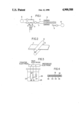
- FIG. 1 is a schematic diagram showing an apparatus for the deposition of a carbon material that is used in the method for the production of a carbon electrode of this invention.
- FIG. 2 is a perspective view showing a rolling process by which a three-dimensional structured substance coated with the carbon material is rolled.
- FIG. 3 is a schematic diagram showing an electrolytic cell that is used to determine the discharging capacity of the carbon electrode of this invention.
- FIG. 4 is a front sectional view showing a thin-type battery constituted by the use of the carbon electrode of this invention.
- the electrode substrate on which a carbon active material is deposited by vapor phase epitaxy is a three-dimensional structured substance, which can be of any shape such as a sponge shape, wool shape, wovencloth shape, nonwoven-cloth shape, net shape, etc., but must have flexibility capable of changing shape due to compression resulting from the application of an external pressure thereto and electroconductivity. Specific examples thereof are metal sponge, woven or nonwoven cloth of metal fibers, metal net, or the like. The thickness thereof is determined based on the degree of the thickness of a desired battery (particularly, a thin-type battery) and the compressibility of the said three-dimensional structured substance.
- the carbon electrode of this invention can be obtained by coating the three-dimensional structured substance with a carbon material (i.e., an electrode active material) and compressing the said coated substance.
- a carbon material i.e., an electrode active material
- the carbon material is deposited on the three-dimensional structured substance by chemical vapor deposition at 1500° C. or less using gaseous hydrocarbons as a gaseous material, examples of which are aliphatic hydrocarbons (preferably, unsaturated hydrocarbons), aromatic hydrocarbons, and alicylic hydrocarbons. These can have substituents, examples of which are halogens, hydroxyl groups, sulfo groups, nitro groups, nitroso groups, amino groups, carboxy groups.
- Aromatic hydrocarbons such as benzene, etc., are preferably used.
- concentration and temperature of hydrocarbon compounds in the atmosphere to be thermally decomposed depend upon the kind of starting hydrocarbon compounds, they are usually set to be several millimolar percent and about 1000° C., respectively.
- a typical method for the vaporization of hydrocarbons is the bubbling method in which argon gas is used as a carrier gas.
- the bubbling method using hydrogen gas or a mixture of hydrogen gas and argon gas can be also used. Evaporation, sublimation, etc., can also employed.
- a carbon material i.e., an electrode active material
- the amount of coating carbon material is preferably in the range of about 1 to about 10 mg/cm 2 .
- the above-mentioned three-dimensional structured substance coated with the carbon material is preferably rolled by means of rollers, but it can be also compressed by a press forming machine or other pressing means.
- the compressing thereof is determined depending upon the thickness of a thin-type battery to which the resulting carbon electrode is applied. It is usually set such that the final thickness becomes 1/2 to 1/10 times the original thickness of the said coated substance.
- a binding agent e.g., a cellulose dispersion
- the binding strength of the carbon material to the three-dimensional structured substance can be maintained at a fixed level even after the compression operation is performed.
- the resulting thin-plate shaped carbon electrode is constituted of an electrode substrate with a high density obtained by compressing the electroconductive and flexible three-dimensional structured substance and a compressed carbon material film with a high density directly placed on the said compressed three-dimensional structured substance.
- the carbon electrode is cut in a predetermined size and each piece is used as an electrode of batteries, particularly thin-type batteries.
- This carbon electrode can be used either as an anode or a cathode.
- the deposition conditions e.g., the thickness of the carbon material, etc.
- oxides such as manganese dioxide, vanadium pentoxide, chromium trioxide, molybdenum trioxide, etc., chalcogen compounds such as titanium disulfide, tantalum disulfide, tantalum selenide, etc., a mixture thereof, or a complex thereof; and electroconductive polymer compounds such as polyacetylene, polyacene etc., can be used.
- the carbon electrode is used as the cathode
- the anode for the anode as a counter electrode, simple light metals such as lithium, sodium, potassium, etc., light metal alloys such as lithiumaluminum alloy, Wood's metal or the like, etc., can be used.
- the carbon electrode of this invention is, of course, applicable to both the anode and the cathode.
- a solution of non-proton organic solvent such as propylene carbonate, dimethoxyethane, etc., containing lithium perchlorate, lithium borofluoride, lithium hexafluoroarsenate, etc., or an acid aqueous solution, an alkaline aqueous solution, etc., containing protons or the like as charge carriers can be used.
- the direct deposition of the carbon material (i.e., an electrode active material) on the electrode substrate was performed, using a reaction apparatus shown in FIG. 1, as follows: To a vessel 1, which contained benzene that had been dehydrated and refined by vacuum distillation, argon gas was supplied from an argon gas supplier 2 so as to bubble the benzene. Then, the benzene was supplied to a quartz reaction tube 4 through a Pyrex glass tube 3.
- the vessel was heated to compensate for energy loss due to evaporation of the benzene, so that the liquid benzene in the vessel 1 could be maintained at a fixed temperature, and the flow rate of the argon gas was controlled by valves 5 and 6 so that the amount of benzene to be supplied into the reaction tube 4 could be controlled at a fixed level.
- the reaction tube 4 there was provided a sample holder 7 on which a three-dimensional structured substance (the length, width and thickness thereof being 50 mm, 50 mm and 1.5 mm, respectively) that is made of foamed nickel was placed.
- a furnace 8 surrounding the outside of the reaction tube 4. This furnace 8 kept the holder 7 and the three-dimensional structured substance on the holder at about 1000 ° C.
- the carbon material that is an electrode active material was directly deposited on the substrate, resulting in an electrode substance.
- the electrode substance 11 was then rolled by rollers 12 and cut into pieces of a predetermined shape, resulting in a carbon electrode.
- Table 1 shows various physical properties of the carbon electrode obtained above and other carbon electrodes obtained likewise using other electrode substrates.
- the discharging capacity of electrodes was determined by the triode method using an electrolytic cell 26 shown in FIG. 3, wherein a test electrode 21 was fixed by a current-collecting rod 22 and lithium electrodes were used for a counter electrode 23 and a reference electrode 24, and an electrolyte 25 was a solution of propylene carbonate containing 1M lithium perchlorate.
- the discharging capacity of the electrode 21 was calculated from the discharged amount of electricity at the time when this electrode was discharged to 2.5 volts after it was charged to the potential that was zero volts with respect to the reference electrode 24 and the discharged amount of electricity at the time when it was discharged to 2.0 volts after it was charged to a potential equal to 4.3 volts.
- the experiments were performed in a glove box capable of maintaining argon atmosphere therein.
- a thin-type battery as shown in FIG. 4 was fabricated using the carbon electrode 31 obtained above, the counter electrode 33 thereof and a separator 35 holding an electrolyte therein.
- Reference numerals 32 and 34 are electrode plates for the carbon electrode 31 and the counter electrode 33, respectively.
- Reference numeral 36 is a sealing substance.
Landscapes
- Chemical & Material Sciences (AREA)
- Chemical Kinetics & Catalysis (AREA)
- General Chemical & Material Sciences (AREA)
- Inorganic Chemistry (AREA)
- Electrochemistry (AREA)
- Engineering & Computer Science (AREA)
- Materials Engineering (AREA)
- Mechanical Engineering (AREA)
- Metallurgy (AREA)
- Organic Chemistry (AREA)
- Battery Electrode And Active Subsutance (AREA)
Abstract
Description
                                  TABLE 1
__________________________________________________________________________
Electrode substrate     Electrode after
                                    Density of
prior to the deposition
                 Compression
                        compression discharging
of carbon material
                 formation
                        formation   capacity of
           Thickness
                 pressure
                        Thickness
                               Density
                                    electrode
No.
   Material
           (mm)  (tcm.sup.-2)
                        (mm)   (gcm.sup.-3)
                                    (mAbcm.sup.-3)
__________________________________________________________________________
1  Foamed nickel
           1.5   0.44   0.300 ± 0.010
                               3.0 ± 0.1
                                    62
2  Foamed nickel
           1.5   2.07   0.210 ± 0.010
                               4.3 ± 0.1
                                    90
3  Foamed nickel
           3.0   0.46   0.540 ± 0.010
                               3.6 ± 0.1
                                    55
4  Foamed nickel
           3.0   1.84   0.370 ± 0.010
                               5.2 ± 0.1
                                    78
5  Wool-shaped
           2.0   0.84   0.130 ± 0.020
                               1.7 ± 0.3
                                    41
   nickel
6  Wool-shaped
           2.0   1.0    0.170 ± 0.020
                               2.9 ± 0.3
                                    33
   copper
7  Nickel net
           0.15  2.07   0.085 ± 0.005
                               4.3 ± 0.2
                                    81
8  Nickel net
           0.15  4.13   0.072 ± 0.005
                               5.0 ± 0.4
                                    96
9  Copper net
           0.27  0.91   0.165 ± 0.005
                               4.2 ± 0.1
                                    45
10 Copper net
           0.27  1.8    0.140 ± 0.005
                               5.0 ± 0.2
                                    57
__________________________________________________________________________
Claims (3)
Applications Claiming Priority (2)
| Application Number | Priority Date | Filing Date | Title |
|---|---|---|---|
| JP61-269426 | 1986-11-11 | ||
| JP61269426A JPH0815074B2 (en) | 1986-11-11 | 1986-11-11 | Method for manufacturing carbon body electrode |
Publications (1)
| Publication Number | Publication Date |
|---|---|
| US4900588A true US4900588A (en) | 1990-02-13 |
Family
ID=17472257
Family Applications (1)
| Application Number | Title | Priority Date | Filing Date |
|---|---|---|---|
| US07/119,115 Expired - Lifetime US4900588A (en) | 1986-11-11 | 1987-11-10 | Method for the production of a carbon electrode |
Country Status (4)
| Country | Link |
|---|---|
| US (1) | US4900588A (en) |
| EP (1) | EP0273562B1 (en) |
| JP (1) | JPH0815074B2 (en) |
| DE (1) | DE3788949T2 (en) |
Cited By (4)
| Publication number | Priority date | Publication date | Assignee | Title |
|---|---|---|---|---|
| US5589299A (en) * | 1994-07-21 | 1996-12-31 | Sharp Kabushiki Kaisha | Carbon electrode for nonaqueous secondary battery, fabrication method for the same and nonaqueous secondary battery using the same |
| US5800941A (en) * | 1995-05-07 | 1998-09-01 | Tadiran Ltd. | Electrochemical cell |
| WO2010088186A3 (en) * | 2009-01-27 | 2010-11-04 | Applied Materials, Inc. | Carbon-based ultracapacitor |
| US20210091372A1 (en) * | 2019-09-23 | 2021-03-25 | International Business Machines Corporation | High capacity compact lithium thin film battery |
Families Citing this family (6)
| Publication number | Priority date | Publication date | Assignee | Title |
|---|---|---|---|---|
| US4863814A (en) * | 1986-03-27 | 1989-09-05 | Sharp Kabushiki Kaisha | Electrode and a battery with the same |
| US4863818A (en) * | 1986-06-24 | 1989-09-05 | Sharp Kabushiki Kaisha | Graphite intercalation compound electrodes for rechargeable batteries and a method for the manufacture of the same |
| JPH0722018B2 (en) * | 1988-03-04 | 1995-03-08 | シャープ株式会社 | Method of manufacturing graphite electrode |
| JP2718696B2 (en) * | 1988-06-08 | 1998-02-25 | シャープ株式会社 | Electrode |
| US5028500A (en) * | 1989-05-11 | 1991-07-02 | Moli Energy Limited | Carbonaceous electrodes for lithium cells |
| RU2260227C1 (en) * | 2003-12-25 | 2005-09-10 | Открытое акционерное общество "Завод "Мезон" | Chemical current supply |
Citations (10)
| Publication number | Priority date | Publication date | Assignee | Title |
|---|---|---|---|---|
| US2289339A (en) * | 1938-08-20 | 1942-07-14 | Joseph B Brennan | Method for making electric devices |
| US3238054A (en) * | 1959-07-02 | 1966-03-01 | Atomic Energy Authority Uk | Method for producing a composite carbon article and articles produced thereby |
| US3399451A (en) * | 1965-03-29 | 1968-09-03 | Chemelex Inc | Methods of coating electrically conductive compositions |
| US3429020A (en) * | 1964-10-21 | 1969-02-25 | Gen Electric | Process for construction of high temperature capacitor |
| US3477940A (en) * | 1966-12-27 | 1969-11-11 | Kimberly Clark Co | Binder containing electrode for electrochemical processes |
| US3629774A (en) * | 1968-10-21 | 1971-12-21 | Scient Advances Inc | Progressively collapsible variable resistance element |
| US3970768A (en) * | 1974-08-03 | 1976-07-20 | English Electric Valve Company Limited | Grid electrodes |
| US4120080A (en) * | 1976-03-27 | 1978-10-17 | U.S. Philips Corporation | Method of manufacturing grid electrodes for electron tubes |
| US4136213A (en) * | 1975-10-16 | 1979-01-23 | Exxon Research & Engineering Co. | Carbon article including electrodes and methods of making the same |
| US4504519A (en) * | 1981-10-21 | 1985-03-12 | Rca Corporation | Diamond-like film and process for producing same |
Family Cites Families (10)
| Publication number | Priority date | Publication date | Assignee | Title |
|---|---|---|---|---|
| US3320093A (en) * | 1963-04-01 | 1967-05-16 | Air Prod & Chem | Method of forming a carbon containing fuel cell electrode |
| FR1402831A (en) * | 1963-09-03 | 1965-06-18 | Inst Francais Du Petrole | oxygen electrode and its manufacture |
| US3964933A (en) * | 1974-04-08 | 1976-06-22 | Exxon Research And Engineering Company | Carbon article including electrodes and methods of making the same |
| US4264686A (en) * | 1978-09-01 | 1981-04-28 | Texas Instruments Incorporated | Graphite felt flowthrough electrode for fuel cell use |
| US4551220A (en) * | 1982-08-03 | 1985-11-05 | Asahi Glass Company, Ltd. | Gas diffusion electrode material |
| JPS6036315A (en) * | 1983-08-10 | 1985-02-25 | Toray Ind Inc | Carbon fiber structure and secondary battery using it |
| JPS617567A (en) * | 1984-06-22 | 1986-01-14 | Hitachi Ltd | Secondary battery and its manufacturing method |
| US4645713A (en) * | 1985-01-25 | 1987-02-24 | Agency Of Industrial Science & Technology | Method for forming conductive graphite film and film formed thereby |
| US4863814A (en) * | 1986-03-27 | 1989-09-05 | Sharp Kabushiki Kaisha | Electrode and a battery with the same |
| JPH0665028B2 (en) * | 1987-09-19 | 1994-08-22 | シャープ株式会社 | Method for manufacturing battery electrode |
-
1986
- 1986-11-11 JP JP61269426A patent/JPH0815074B2/en not_active Expired - Fee Related
-
1987
- 1987-11-10 US US07/119,115 patent/US4900588A/en not_active Expired - Lifetime
- 1987-11-11 EP EP87309986A patent/EP0273562B1/en not_active Expired - Lifetime
- 1987-11-11 DE DE87309986T patent/DE3788949T2/en not_active Expired - Fee Related
Patent Citations (10)
| Publication number | Priority date | Publication date | Assignee | Title |
|---|---|---|---|---|
| US2289339A (en) * | 1938-08-20 | 1942-07-14 | Joseph B Brennan | Method for making electric devices |
| US3238054A (en) * | 1959-07-02 | 1966-03-01 | Atomic Energy Authority Uk | Method for producing a composite carbon article and articles produced thereby |
| US3429020A (en) * | 1964-10-21 | 1969-02-25 | Gen Electric | Process for construction of high temperature capacitor |
| US3399451A (en) * | 1965-03-29 | 1968-09-03 | Chemelex Inc | Methods of coating electrically conductive compositions |
| US3477940A (en) * | 1966-12-27 | 1969-11-11 | Kimberly Clark Co | Binder containing electrode for electrochemical processes |
| US3629774A (en) * | 1968-10-21 | 1971-12-21 | Scient Advances Inc | Progressively collapsible variable resistance element |
| US3970768A (en) * | 1974-08-03 | 1976-07-20 | English Electric Valve Company Limited | Grid electrodes |
| US4136213A (en) * | 1975-10-16 | 1979-01-23 | Exxon Research & Engineering Co. | Carbon article including electrodes and methods of making the same |
| US4120080A (en) * | 1976-03-27 | 1978-10-17 | U.S. Philips Corporation | Method of manufacturing grid electrodes for electron tubes |
| US4504519A (en) * | 1981-10-21 | 1985-03-12 | Rca Corporation | Diamond-like film and process for producing same |
Non-Patent Citations (6)
| Title |
|---|
| Blaedel et al., "Pyolytic Carbon Film Electrode", Analytical Chemistry, vol. 50, No. 7, pp. 933-936, Jun. 1978. |
| Blaedel et al., Pyolytic Carbon Film Electrode , Analytical Chemistry, vol. 50, No. 7, pp. 933 936, Jun. 1978. * |
| S. L. Deshpande et al., J. Electrochem Soc (1978) 125: 687 692. * |
| S. L. Deshpande et al., J. Electrochem Soc (1978) 125: 687-692. |
| Y. Onuma et al., Jpn J. Appl. Phys (1983) 22:888 889. * |
| Y. Onuma et al., Jpn J. Appl. Phys (1983) 22:888-889. |
Cited By (6)
| Publication number | Priority date | Publication date | Assignee | Title |
|---|---|---|---|---|
| US5589299A (en) * | 1994-07-21 | 1996-12-31 | Sharp Kabushiki Kaisha | Carbon electrode for nonaqueous secondary battery, fabrication method for the same and nonaqueous secondary battery using the same |
| US5800941A (en) * | 1995-05-07 | 1998-09-01 | Tadiran Ltd. | Electrochemical cell |
| WO2010088186A3 (en) * | 2009-01-27 | 2010-11-04 | Applied Materials, Inc. | Carbon-based ultracapacitor |
| US8178155B2 (en) | 2009-01-27 | 2012-05-15 | Applied Materials, Inc. | Carbon-based ultracapacitor |
| US20210091372A1 (en) * | 2019-09-23 | 2021-03-25 | International Business Machines Corporation | High capacity compact lithium thin film battery |
| US12506137B2 (en) * | 2019-09-23 | 2025-12-23 | International Business Machines Corporation | High capacity compact lithium thin film battery |
Also Published As
| Publication number | Publication date |
|---|---|
| DE3788949D1 (en) | 1994-03-10 |
| EP0273562A2 (en) | 1988-07-06 |
| DE3788949T2 (en) | 1994-05-05 |
| EP0273562B1 (en) | 1994-01-26 |
| JPS63124363A (en) | 1988-05-27 |
| JPH0815074B2 (en) | 1996-02-14 |
| EP0273562A3 (en) | 1989-09-27 |
Similar Documents
| Publication | Publication Date | Title |
|---|---|---|
| US4863814A (en) | Electrode and a battery with the same | |
| EP0251677B1 (en) | Graphite intercalation compound electrodes for rechargeable batteries and a method for the manufacture of the same | |
| Chen et al. | Carbon nanotube network modified carbon fibre paper for Li-ion batteries | |
| EP2387805B1 (en) | A process for producing carbon nanostructure on a flexible substrate, and energy storage devices comprising flexible carbon nanostructure electrodes | |
| US5344726A (en) | Carbon anode for secondary battery | |
| KR100326975B1 (en) | Carbonaceous particles and carbonaceous fibers both coated with boron nitride, and lithium secondary cells produced by using the same as negative active material | |
| US10033036B2 (en) | Metal/oxygen battery with internal oxygen reservoir | |
| US4835075A (en) | Secondary battery using nonaqueous electrolytes | |
| US5139901A (en) | Lithium secondary battery using hydric boron carbonitride as electrode material | |
| US4900588A (en) | Method for the production of a carbon electrode | |
| Plichta et al. | The Rechargeable Li x TiS2/LiAlCl4/Li1− x CoO2 Solid‐State Cell | |
| WO2014074332A1 (en) | Carbon nanotubes attached to metal foil | |
| ITRM950411A1 (en) | LITHIUM-ION ACCUMULATORS IN WHICH A CARBON ELECTRODIC MATERIAL IS USED AS ANODE. | |
| US4931240A (en) | Method for the production of a carbon electrode | |
| US4994221A (en) | Method for the production of a carbon electrode | |
| JPS63213258A (en) | electrode | |
| CN114032532B (en) | Sodium metal battery current collector and preparation method and application thereof | |
| JP2584753B2 (en) | Method for producing electrode for non-aqueous electrolyte secondary battery | |
| JP2617182B2 (en) | Rechargeable battery | |
| JP2656003B2 (en) | Non-aqueous secondary battery | |
| JP2785909B2 (en) | Non-aqueous secondary battery | |
| JP2707171B2 (en) | Method for producing carbon for battery active material | |
| JPH01105469A (en) | Carbon electrode | |
| JPH03266358A (en) | Carbon electrode manufacturing method and non-aqueous secondary battery | |
| JPH0828238B2 (en) | Non-aqueous secondary battery |
Legal Events
| Date | Code | Title | Description |
|---|---|---|---|
| AS | Assignment |
Owner name: SHARP KABUSHIKI KAISHA, 22-22, NAGAIKE-CHO, ABENO- Free format text: ASSIGNMENT OF ASSIGNORS INTEREST.;ASSIGNORS:MOHRI, MOTOO;TANAKA, HIDEAKA;TAJIMA, YOSHIMITSU;REEL/FRAME:004823/0269 Effective date: 19871221 Owner name: SHARP KABUSHIKI KAISHA,JAPAN Free format text: ASSIGNMENT OF ASSIGNORS INTEREST;ASSIGNORS:MOHRI, MOTOO;TANAKA, HIDEAKA;TAJIMA, YOSHIMITSU;REEL/FRAME:004823/0269 Effective date: 19871221 |
|
| AS | Assignment |
Owner name: SHARP KABUSHIKI KAISHA, 22-22, NAGAIKE-CHO, ABENO- Free format text: ASSIGNMENT OF ASSIGNORS INTEREST.;ASSIGNORS:TAJIMA, YOSHIMITSU;MOHRI, MOTOO;TANAKA, HIDEAKI;REEL/FRAME:004859/0225 Effective date: 19871229 Owner name: SHARP KABUSHIKI KAISHA, JAPAN Free format text: ASSIGNMENT OF ASSIGNORS INTEREST;ASSIGNORS:TAJIMA, YOSHIMITSU;MOHRI, MOTOO;TANAKA, HIDEAKI;REEL/FRAME:004859/0225 Effective date: 19871229 |
|
| STCF | Information on status: patent grant |
Free format text: PATENTED CASE |
|
| FEPP | Fee payment procedure |
Free format text: PAYOR NUMBER ASSIGNED (ORIGINAL EVENT CODE: ASPN); ENTITY STATUS OF PATENT OWNER: LARGE ENTITY |
|
| FPAY | Fee payment |
Year of fee payment: 4 |
|
| FEPP | Fee payment procedure |
Free format text: PAYER NUMBER DE-ASSIGNED (ORIGINAL EVENT CODE: RMPN); ENTITY STATUS OF PATENT OWNER: LARGE ENTITY Free format text: PAYOR NUMBER ASSIGNED (ORIGINAL EVENT CODE: ASPN); ENTITY STATUS OF PATENT OWNER: LARGE ENTITY |
|
| FPAY | Fee payment |
Year of fee payment: 8 |
|
| FPAY | Fee payment |
Year of fee payment: 12 |