US4900400A - Arrangement for liquid treatment of pulp - Google Patents
Arrangement for liquid treatment of pulp Download PDFInfo
- Publication number
- US4900400A US4900400A US07/249,569 US24956988A US4900400A US 4900400 A US4900400 A US 4900400A US 24956988 A US24956988 A US 24956988A US 4900400 A US4900400 A US 4900400A
- Authority
- US
- United States
- Prior art keywords
- treatment liquid
- pulp suspension
- belt
- flow
- plate members
- Prior art date
- Legal status (The legal status is an assumption and is not a legal conclusion. Google has not performed a legal analysis and makes no representation as to the accuracy of the status listed.)
- Expired - Fee Related
Links
Images

Classifications
-
- D—TEXTILES; PAPER
- D21—PAPER-MAKING; PRODUCTION OF CELLULOSE
- D21C—PRODUCTION OF CELLULOSE BY REMOVING NON-CELLULOSE SUBSTANCES FROM CELLULOSE-CONTAINING MATERIALS; REGENERATION OF PULPING LIQUORS; APPARATUS THEREFOR
- D21C9/00—After-treatment of cellulose pulp, e.g. of wood pulp, or cotton linters ; Treatment of dilute or dewatered pulp or process improvement taking place after obtaining the raw cellulosic material and not provided for elsewhere
- D21C9/02—Washing ; Displacing cooking or pulp-treating liquors contained in the pulp by fluids, e.g. wash water or other pulp-treating agents
- D21C9/06—Washing ; Displacing cooking or pulp-treating liquors contained in the pulp by fluids, e.g. wash water or other pulp-treating agents in filters ; Washing of concentrated pulp, e.g. pulp mats, on filtering surfaces
-
- B—PERFORMING OPERATIONS; TRANSPORTING
- B01—PHYSICAL OR CHEMICAL PROCESSES OR APPARATUS IN GENERAL
- B01D—SEPARATION
- B01D33/00—Filters with filtering elements which move during the filtering operation
- B01D33/04—Filters with filtering elements which move during the filtering operation with filtering bands or the like supported on cylinders which are impervious for filtering
-
- B—PERFORMING OPERATIONS; TRANSPORTING
- B01—PHYSICAL OR CHEMICAL PROCESSES OR APPARATUS IN GENERAL
- B01D—SEPARATION
- B01D33/00—Filters with filtering elements which move during the filtering operation
- B01D33/44—Regenerating the filter material in the filter
-
- B—PERFORMING OPERATIONS; TRANSPORTING
- B01—PHYSICAL OR CHEMICAL PROCESSES OR APPARATUS IN GENERAL
- B01D—SEPARATION
- B01D33/00—Filters with filtering elements which move during the filtering operation
- B01D33/70—Filters with filtering elements which move during the filtering operation having feed or discharge devices
Definitions
- the present invention is directed to apparatus for treating a pulp suspension with a treatment liquid.
- the supply of treatment liquid is affected by a plurality of liquid supply devices located above the belt.
- Each such supply device normally sprays a liquid both in the direction in which the belt is running, and in the opposite direction thereagainst. In order to make maximum use of the liquid flow, half of it is thus directed in either direction.
- the liquid applied countercurrently has a tendency to mix with the liquid content of the pulp instead of displacing the pulp, primarily because of the large impulse against the pulp web created thereby.
- an apparatus for treating the pulp suspension with a treatment liquid comprising a continuous liquid pervious belt for receiving the pulp suspension and moving the pulp suspension through a treatment zone in a predetermined direction.
- the treatment liquid supply means is located above the continuous belt in the treatment zone for supplying treatment liquid onto the pulp suspension as it travels through the treatment zone, and collection means are located below the continuous belt for receiving liquid passing through the pulp suspension.
- the treatment liquid supply means comprises a treatment liquid feed pipe for supplying a flow of the treatment liquid and distribution means for dividing that flow of treatment liquid into first and second flow components.
- the first flow component is disposed in the predetermined direction in which the belt is travelling, and the second flow component is disposed counter to that predetermined direction.
- Deflecting means are supplied for deflecting the second flow component into that predetermined direction, along with application means comprising first and second plate members for applying the first and second flow components onto the pulp suspension respectively, whereby the amount of the treatment liquid supplied to the pulp suspension is controlled.
- the distribution means which are substantially symmetrical to the feed pipe.
- the treatment liquid supply means extends across the entire width of the belt.
- each of the first and second plate members includes at least one gap for supply of at least a portion of the first and second flow components therethrough.
- first and second plate members are provided, including guide lip means associated with each of said at least one gap associated therewith. More preferably, guide lip means are also provided, located at the downstream edge of said at least one gap.
- guide lip means are provided obliquely disposed with respect to said first and second plate members.
- each of the first and second plate members includes end guide lip means at the ends of the plate members, and more preferably, the end guide lip means are obliquely disposed with respect to the first and second plate members.
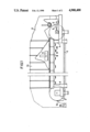
- FIG. 1 is a side elevational view of an apparatus in accordance with the present invention.
- FIG. 2 is a cross-sectional view of the apparatus shown in FIG. 1.
- the present apparatus for the liquid treatment of pulp as shown in FIG. 1 comprises a stand 4, with two end rolls 2 and 3, over which an endless liquid pervious belt 1, runs.
- the belt is a wire or a perforated belt, for example, a steel belt.
- the belt is driven by end roll 3, and slides over perforated covers on containers 8, located therebeneath.
- a head box 6, for supply of pulp is located at one end of the belt.
- means 14 for transferring the treated pulp is provided.
- Devices 11, for the supply of treatment liquid to the pulp are located above the belt 1.
- the containers 8, located beneath are intended for collecting liquid. Both the devices for the supply of treatment liquid and the liquid receiving containers are placed in the transverse direction across the entire belt width, which amounts to 6 m, and in certain cases can still be wider.
- a continuous belt 1 runs about a first end roll 2, and second end roll 3.
- the rolls are arranged in a stand 4, in such a manner that the first end roll 2 is movable by means of a stretching device 5, preferably a hydraulic one, for adjusting the belt tension.
- the driving is effected by the second end roll 3.
- a head box 6, is located for distributing the cellulose pulp in a uniform layer 7, on the belt 1.
- a plurality of containers 8, are arranged one after the other in the longitudinal direction of the belt 1.
- the containers 8, are provided with perforated covers in support of the belt 1.
- Outlets 9 and 10 are connected to the containers 8 for the discharge of liquid, vapors and gases.
- the liquid outlets 9 and 10 are located on the bottom of the containers 8 to insure effective drainage.
- the liquid level in the containers 8 is controlled by a special means so that a little space for the vapors and gases is maintained in the upper part of the containers 8. Thereby, the drop of the liquid from the belt 1 down into the containers is small, thereby reducing the tendency of foaming.
- a pressure difference is maintained over the pulp layer 7, in order to effect liquid transport transversely through the pulp layer.
- a hood 13 is provided above the belt.
- a transfer device 14 for the completely treated pulp layer is provided which device, for example, is a doctor blade. Beneath the doctor blade a conveying screw 15, is located for conveying the pulp to subsequent processing steps.
- Each device 11 for the supply of treatment liquid comprises a feed pipe 16, distribution means 17, deflecting means 18, and application means in the form of a front plate 19 and a rear plate 20.
- the leading edge on each plate is provided with a lip 21, which is angled obliquely downwardly to the belt.
- Both plates 19 and 20 are provided with a gap 22. Several gaps may possibly be arranged one after the other in the plates 19 and 20. In connection with each gap 22, a guide lip 23 is located.
- the treatment liquid flows through the feed pipe 16, down into the distribution means 17, which should be substantially symmetrical relative to the feed pipe 16.
- the liquid flow is divided by the distribution means 17 into two parts, concurrent and countercurrent to the running direction of the belt 1.
- the concurrent flow thereafter flows onto the front plate 19 of the application means.
- the countercurrent flow is first turned through 180° by the deflecting means 18 before it flows onto the rear plate 20 of the application means.
- the liquid flow passing through each supply device 11 depends on a great number of factors such as belt speed, pulp layer thickness, distance between the supply devices, pressure drop over the pulp layer, and nature of the treatment liquid, as well as the pulp.
- the apparatus of the present invention provides liquid flows up to 13 m 3 treatment liquid per ton of treated pulp. This indicates flows of up to 10,000 liters per minute at a production of 1,000 tons of pulp per 24 hours. In certain cases, even greater flows can be applied due to the fact that the liquid, according to the invention, is applied concurrent with the direction of the moving belt, and divided into partial flows. Also, the conditions for displacing the liquid in the pulp layer are very favorable. Accordingly, both the pulp treatment efficiency and the production of treated pulp can be increased by at least 10% compared with prior art techniques.
- the size of the gaps 22 may be adjusted and is preferably within the range of 10-20 mm.
- the lips 21 and guide lips 23 each form an obliquely downward angle with the plates 19 and 20 of the application means of about 25-45° , preferably 30-40° .
- the guide lips 23 are located in the downstream edge of the gaps 22 and also form an obliquely downward angle with plates 19 and 20. The distance between the plates 19 and 20 of the application means and the pulp suspension is minimized and preferably smaller than 50 mm.
Landscapes
- Chemical & Material Sciences (AREA)
- Chemical Kinetics & Catalysis (AREA)
- Life Sciences & Earth Sciences (AREA)
- Engineering & Computer Science (AREA)
- Wood Science & Technology (AREA)
- Paper (AREA)
- Electrical Discharge Machining, Electrochemical Machining, And Combined Machining (AREA)
- Extraction Or Liquid Replacement (AREA)
- Filtration Of Liquid (AREA)
- Steroid Compounds (AREA)
Abstract
Description
Claims (10)
Applications Claiming Priority (2)
| Application Number | Priority Date | Filing Date | Title |
|---|---|---|---|
| SE8602150 | 1986-05-13 | ||
| SE8602150A SE448890B (en) | 1986-05-13 | 1986-05-13 | DEVICE FOR THE SUPPLY OF LIQUID IN TREATMENT OF PASS ON AN ENDLESS, CURRENT RANGE |
Publications (1)
| Publication Number | Publication Date |
|---|---|
| US4900400A true US4900400A (en) | 1990-02-13 |
Family
ID=20364497
Family Applications (1)
| Application Number | Title | Priority Date | Filing Date |
|---|---|---|---|
| US07/249,569 Expired - Fee Related US4900400A (en) | 1986-05-13 | 1987-04-15 | Arrangement for liquid treatment of pulp |
Country Status (12)
| Country | Link |
|---|---|
| US (1) | US4900400A (en) |
| EP (1) | EP0305394B1 (en) |
| JP (1) | JPH07109071B2 (en) |
| AT (1) | ATE66976T1 (en) |
| AU (1) | AU596190B2 (en) |
| CA (1) | CA1275593C (en) |
| DE (2) | DE305394T1 (en) |
| FI (1) | FI89387C (en) |
| NO (1) | NO166804C (en) |
| NZ (1) | NZ220108A (en) |
| SE (1) | SE448890B (en) |
| WO (1) | WO1987006962A1 (en) |
Cited By (1)
| Publication number | Priority date | Publication date | Assignee | Title |
|---|---|---|---|---|
| US5238501A (en) * | 1989-07-03 | 1993-08-24 | Maschinenfabrik Andritz Aktiengesellschaft | Method for treatment of a fibrous material-fluid mixture |
Citations (5)
| Publication number | Priority date | Publication date | Assignee | Title |
|---|---|---|---|---|
| US2185868A (en) * | 1937-12-15 | 1940-01-02 | Curt C Schaefer | Filtering machine |
| DE2906254A1 (en) * | 1978-02-22 | 1979-08-30 | Rhone Poulenc Ind | DISTRIBUTION BOX FOR FILTER |
| WO1985002424A1 (en) * | 1983-12-02 | 1985-06-06 | Sunds Defibrator Aktiebolag | Pulp washer |
| US4569762A (en) * | 1983-02-04 | 1986-02-11 | Guy Gaudfrin | Belt filter equipped with an air suction device |
| US4657637A (en) * | 1984-09-17 | 1987-04-14 | Sunds Defibrator Aktiebolag | Pulp treatment apparatus having lowerable vacuum containers to facilitate removal thereof |
Family Cites Families (1)
| Publication number | Priority date | Publication date | Assignee | Title |
|---|---|---|---|---|
| CH236124A (en) * | 1941-12-06 | 1945-01-15 | Siemens Planiawerke Ag | Method for connecting continuously operating carbon electrodes for electric furnaces. |
-
1986
- 1986-05-13 SE SE8602150A patent/SE448890B/en not_active IP Right Cessation
-
1987
- 1987-04-15 EP EP87903455A patent/EP0305394B1/en not_active Expired - Lifetime
- 1987-04-15 AT AT87903455T patent/ATE66976T1/en not_active IP Right Cessation
- 1987-04-15 DE DE198787903455T patent/DE305394T1/en active Pending
- 1987-04-15 US US07/249,569 patent/US4900400A/en not_active Expired - Fee Related
- 1987-04-15 DE DE8787903455T patent/DE3772768D1/en not_active Expired - Fee Related
- 1987-04-15 AU AU74301/87A patent/AU596190B2/en not_active Ceased
- 1987-04-15 WO PCT/SE1987/000192 patent/WO1987006962A1/en not_active Ceased
- 1987-04-15 JP JP62503058A patent/JPH07109071B2/en not_active Expired - Lifetime
- 1987-04-27 NZ NZ220108A patent/NZ220108A/en unknown
- 1987-05-12 CA CA000536883A patent/CA1275593C/en not_active Expired - Fee Related
-
1988
- 1988-01-12 NO NO880102A patent/NO166804C/en unknown
- 1988-11-11 FI FI885241A patent/FI89387C/en not_active IP Right Cessation
Patent Citations (5)
| Publication number | Priority date | Publication date | Assignee | Title |
|---|---|---|---|---|
| US2185868A (en) * | 1937-12-15 | 1940-01-02 | Curt C Schaefer | Filtering machine |
| DE2906254A1 (en) * | 1978-02-22 | 1979-08-30 | Rhone Poulenc Ind | DISTRIBUTION BOX FOR FILTER |
| US4569762A (en) * | 1983-02-04 | 1986-02-11 | Guy Gaudfrin | Belt filter equipped with an air suction device |
| WO1985002424A1 (en) * | 1983-12-02 | 1985-06-06 | Sunds Defibrator Aktiebolag | Pulp washer |
| US4657637A (en) * | 1984-09-17 | 1987-04-14 | Sunds Defibrator Aktiebolag | Pulp treatment apparatus having lowerable vacuum containers to facilitate removal thereof |
Cited By (2)
| Publication number | Priority date | Publication date | Assignee | Title |
|---|---|---|---|---|
| US5238501A (en) * | 1989-07-03 | 1993-08-24 | Maschinenfabrik Andritz Aktiengesellschaft | Method for treatment of a fibrous material-fluid mixture |
| US5517834A (en) * | 1989-07-03 | 1996-05-21 | Maschinenfabrik Andritz Actiengesellschaft | Method and device for treatment of a fibrous material-fluid mixture |
Also Published As
| Publication number | Publication date |
|---|---|
| FI89387B (en) | 1993-06-15 |
| JPH07109071B2 (en) | 1995-11-22 |
| SE8602150D0 (en) | 1986-05-13 |
| FI885241A0 (en) | 1988-11-11 |
| AU7430187A (en) | 1987-12-01 |
| NO166804C (en) | 1991-09-04 |
| FI885241L (en) | 1988-11-11 |
| DE305394T1 (en) | 1989-06-22 |
| DE3772768D1 (en) | 1991-10-10 |
| ATE66976T1 (en) | 1991-09-15 |
| EP0305394B1 (en) | 1991-09-04 |
| FI89387C (en) | 1993-09-27 |
| JPH01502597A (en) | 1989-09-07 |
| AU596190B2 (en) | 1990-04-26 |
| CA1275593C (en) | 1990-10-30 |
| NO166804B (en) | 1991-05-27 |
| NO880102D0 (en) | 1988-01-12 |
| EP0305394A1 (en) | 1989-03-08 |
| SE448890B (en) | 1987-03-23 |
| NZ220108A (en) | 1988-08-30 |
| NO880102L (en) | 1988-01-12 |
| WO1987006962A1 (en) | 1987-11-19 |
Similar Documents
| Publication | Publication Date | Title |
|---|---|---|
| US6419217B1 (en) | Drawings-in- of paper webs | |
| US8434338B2 (en) | Device for cooling a metal strip | |
| US5517834A (en) | Method and device for treatment of a fibrous material-fluid mixture | |
| US4025671A (en) | Method for applying continuous longitudinal bands of liquid coating to a moving strip | |
| EP0675984B1 (en) | Apparatus and method of minimizing skip coating on a paper web | |
| DE4106084A1 (en) | ROTARY CUTTER | |
| EP0755887B1 (en) | Method and device for pneumatically slowing down sheets in the delivery device of a rotary sheet printing machine | |
| US4900400A (en) | Arrangement for liquid treatment of pulp | |
| US5286230A (en) | Apparatus for dividing deep-frozen foodstuffs, with recovery of foodstuffs detached during said division | |
| FI64202C (en) | moving base | |
| DE3139739A1 (en) | "RAIL COATING DEVICE" | |
| US3149026A (en) | Air assisted formation method and apparatus | |
| EP0757129B1 (en) | Application system for a device for coating a paper or paperboard sheet | |
| US4184846A (en) | Method and apparatus for liquid processing of tubular knitted fabrics | |
| US4610144A (en) | Cooling of metal strip | |
| CA2198264A1 (en) | Method and device for coating strips of material, in particular paper orcardboard | |
| AU596172B2 (en) | Apparatus for liquid treatment of pulp | |
| CA1265691A (en) | Pulp washer | |
| EP0523264B1 (en) | Device for making single-faces corrugated paper | |
| US20040173112A1 (en) | Rewetting installation for a material web and a method for improving the anti-frictional properties of a material web | |
| EP0254899A1 (en) | Drainage apparatus | |
| DE19750555A1 (en) | Longitudinal folding device for printed web | |
| DE1522872B (en) | Film processor | |
| DE8309902U1 (en) | DEVICE FOR BRAKING AND OVERLAPPING PAPER SHEETS IN PAPER PROCESSING MACHINES | |
| AT508974A2 (en) | APPARATUS AND METHOD FOR TREATING A FIBERWORK |
Legal Events
| Date | Code | Title | Description |
|---|---|---|---|
| AS | Assignment |
Owner name: SUNDS DEFIBRATOR AKTIEBOLAG, S-851 94 SUNDSVALL, S Free format text: ASSIGNMENT OF ASSIGNORS INTEREST.;ASSIGNORS:GUDMUNDSSON, PER E. W.;LINDSTROM, ALF I.;BERG, JAN-ERIK;REEL/FRAME:004956/0353 Effective date: 19880822 Owner name: SUNDS DEFIBRATOR AKTIEBOLAG, A CORP. OF SWEDEN,SWE Free format text: ASSIGNMENT OF ASSIGNORS INTEREST;ASSIGNORS:GUDMUNDSSON, PER E. W.;LINDSTROM, ALF I.;BERG, JAN-ERIK;REEL/FRAME:004956/0353 Effective date: 19880822 |
|
| FEPP | Fee payment procedure |
Free format text: PAYOR NUMBER ASSIGNED (ORIGINAL EVENT CODE: ASPN); ENTITY STATUS OF PATENT OWNER: LARGE ENTITY |
|
| FPAY | Fee payment |
Year of fee payment: 4 |
|
| FEPP | Fee payment procedure |
Free format text: PAYOR NUMBER ASSIGNED (ORIGINAL EVENT CODE: ASPN); ENTITY STATUS OF PATENT OWNER: LARGE ENTITY Free format text: PAYER NUMBER DE-ASSIGNED (ORIGINAL EVENT CODE: RMPN); ENTITY STATUS OF PATENT OWNER: LARGE ENTITY |
|
| FPAY | Fee payment |
Year of fee payment: 8 |
|
| REMI | Maintenance fee reminder mailed | ||
| LAPS | Lapse for failure to pay maintenance fees | ||
| STCH | Information on status: patent discontinuation |
Free format text: PATENT EXPIRED DUE TO NONPAYMENT OF MAINTENANCE FEES UNDER 37 CFR 1.362 |
|
| FP | Lapsed due to failure to pay maintenance fee |
Effective date: 20020213 |