US4900289A - Mechanism for animating a doll's facial features - Google Patents
Mechanism for animating a doll's facial features Download PDFInfo
- Publication number
- US4900289A US4900289A US07/149,712 US14971288A US4900289A US 4900289 A US4900289 A US 4900289A US 14971288 A US14971288 A US 14971288A US 4900289 A US4900289 A US 4900289A
- Authority
- US
- United States
- Prior art keywords
- motor
- rotation
- movement
- animated
- cam
- Prior art date
- Legal status (The legal status is an assumption and is not a legal conclusion. Google has not performed a legal analysis and makes no representation as to the accuracy of the status listed.)
- Expired - Fee Related
Links
- 230000007246 mechanism Effects 0.000 title claims abstract description 34
- 230000001815 facial effect Effects 0.000 title claims abstract description 16
- 210000000744 eyelid Anatomy 0.000 claims abstract description 19
- 230000008878 coupling Effects 0.000 claims description 18
- 238000010168 coupling process Methods 0.000 claims description 18
- 238000005859 coupling reaction Methods 0.000 claims description 18
- 210000005252 bulbus oculi Anatomy 0.000 claims description 13
- 230000002457 bidirectional effect Effects 0.000 claims description 6
- 230000002441 reversible effect Effects 0.000 claims description 3
- 230000006835 compression Effects 0.000 claims description 2
- 238000007906 compression Methods 0.000 claims description 2
- 230000006872 improvement Effects 0.000 claims description 2
- 230000008859 change Effects 0.000 claims 3
- 210000001847 jaw Anatomy 0.000 claims 1
- 230000004044 response Effects 0.000 claims 1
- 210000001508 eye Anatomy 0.000 abstract description 9
- 230000001360 synchronised effect Effects 0.000 abstract description 2
- 241001293250 Lagascea decipiens Species 0.000 description 5
- 230000004397 blinking Effects 0.000 description 4
- 230000008901 benefit Effects 0.000 description 3
- 230000000694 effects Effects 0.000 description 2
- 230000004424 eye movement Effects 0.000 description 2
- 238000010348 incorporation Methods 0.000 description 2
- 230000004048 modification Effects 0.000 description 2
- 238000012986 modification Methods 0.000 description 2
- 241000905358 Actaea pachypoda Species 0.000 description 1
- 230000009471 action Effects 0.000 description 1
- 230000003247 decreasing effect Effects 0.000 description 1
- 210000003128 head Anatomy 0.000 description 1
- 230000003252 repetitive effect Effects 0.000 description 1
Images
Classifications
-
- A—HUMAN NECESSITIES
- A63—SPORTS; GAMES; AMUSEMENTS
- A63H—TOYS, e.g. TOPS, DOLLS, HOOPS OR BUILDING BLOCKS
- A63H3/00—Dolls
- A63H3/36—Details; Accessories
- A63H3/365—Details; Accessories allowing a choice of facial features, e.g. to change the facial expression
Definitions
- the present invention relates generally to improvements in mechanisms that serve to animate a doll's facial features, and, more particularly, pertains to a mechanism in which a single motor drives simulated jaw movement, eyeball movement and eyelid movement.
- the eyelid movement is achieved in a manner such that it can be initiated at any time independent of jaw or eyeball position.
- Miniaturization of electronic circuitry has enabled the incorporation of a surprising amount of sophisticated capability within a doll's interior.
- the coordinated movement of legs, arms, hands, head and various facial features has become a rather commonplace ability of modern dolls.
- such movements can be coordinated with a sound track emanating from the doll.
- An increased number of movements that are coordinated with a sound track results in a more lifelike appearance.
- a shortcoming of mechanisms that are driven by a single drive means is that the sequence of movements is typically very repetitive, therefore rather predictable, and as a result, has a rather artificial appearance. While the use of complex cam profiles somewhat lessens the movements' rather “mechanical" appearance, independence of one movement from another is not thereby achieved. For instance, it could be observed that for every so many eye movements or jaw movements, the eyelids are blinked. Incorporation of additional drive means provides more degrees of independence but complicates matters by increasing size, weight, cost and complexity. Similarly, addition of mechanisms that can selectively couple and decouple certain functions from a single drive means increases complexity and cost.
- An object of the present invention is to provide a mechanism by which three separate types of movement can be imparted to a doll's facial features, all being controlled and driven by a single drive means.
- the foregoing and other objects are attained by a unique arrangement of gears, pulleys, cranks and couplings whereby a single drive means can simultaneously power different types of movements so that they appear to operate independently of one another. While one type of movement is continuously driven while the drive means is operational, the other type of movement is limited to a specified number of cycles, initiated whenever the direction of rotation of the drive means is reversed.
- This arrangement has the advantage that when, for example, adapted to drive various facial movements in an animated doll, by simply controlling the voltage supplied to a bidirectional motor, the rate of eye and jaw movement can be controlled while the eyelids can be "blinked" whenever desired by simply reversing the voltage bias.
- a further advantage of the present invention is that the entire mechanism is compact and can therefore be entirely accommodated within, for example, a doll's head.
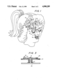
- FIG. 1 is a perspective view of components of the mechanism of the present invention as arranged inside a doll's head;
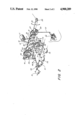
- FIG. 2 is a schematic representation of the mechanism of the present invention.
- FIG. 3 is an elevated side view of the friction coupling.
- the mechanism described herein can be incorporated in a doll containing audio reproduction and control equipment which, in addition to having a sound track, generates signals for powering an electric motor at various intervals, at varying speeds and in different directions.
- the entire mechanism including its electric motor, is arranged within a doll's head as is illustrated in FIG. 1.
- the mechanism powers movement of the eyes, the jaw and the eyelids.
- Signals generated elsewhere within the doll which can, for example, be read off a magnetic tape, coordinates and synchronizes the various movement.
- Jaw movement can be synchronized with a voice track, while eyes can scan in a continuous sequence.
- the eyelids can be blinked at apparently random intervals. All these functions are controlled by a single pair of leads that supply the voltage to the electric motor.
- FIG. 2 schematically illustrates a mechanism of the present invention.
- the drive means 11 may, for example, be an electric motor capable of variable speeds in both forward and reverse rotation.
- a pair of pulleys 15, 17 transfers the rotation from the motor to the gear trains via drive belt 13.
- the utilization of a belt and pulleys at this point serves to both reduce the rate of rotation and to provide a built-in safety feature. In the event one of the gear trains should become jammed or one of the drive movements is in some way restricted, slippage of the belt 13 will prevent the electric motor 11 from burnout.
- Rotation of pulley 17 is transferred to the rotation of a cam 21 via gear train 19.
- Cam 21 has a complex profile 29 in the form of a groove.
- Lever 23 is pivotably attached at 25, and has a peg 27 which rides in the groove. This causes a generally up and down motion of the arm as the cam is rotated.
- a connecting rod 31 connects this movement to the movement of the mouth or jaw of the doll 33.
- the speed of the motor 11 can be altered as is necessary to coordinate the jaw movement with the rate of speech or can be stopped during moments of silence. It is to be observed that the net jaw movement is unaffected by the direction of rotation of the cam or motor.
- a second gear train 35 translates the rotational movement of pulley 17 to cam 37.
- a lever arm 39 appropriately positioned and pivoting about 41 follows the complex cam profile 43 via cam follower 45.
- a spring 47 urges the lever against the cam surface.
- the linkage 49 links this movement to a side-to-side movement of eyeballs 51 and tie rod 53 ensures a coordinated movement of both eyeballs.
- the transfer ratio of gear train 35 serves to drive cam 37 at a much lower rate than cam 21, as the resulting eye movement must be considerably slower than the jaw movement to impart a realistic animation. Again, it is to be observed that this movement is unaffected by the actual direction of rotation of the motor. Seemingly random scanning of the eyeballs from side to side appears equally as random in either direction of rotation of 37.
- a third gear train 55 translates the rotational movement to gear 57.
- friction disk 59 is concentrically disposed above gear 57 via axle 61. Both gear 57, the drive member, and friction disk 59, the driven member, are free to rotate about axle 61.
- a coil spring 63 disposed about axle 61 in compression between 57 and a portion of the housing 60, urges gear 57 against friction disk 59 and thereby frictionally links the rotation of the two components.
- a peg 65 projects up above the surface of the friction disk 59 in a direction parallel with the axis 61. This positioning in effect renders its operation that of a crank.
- Arm 67 pivots around 71 and slot 69 engages peg 65 such that rotation of friction disk 59 results in an up and down motion of crank 67.
- the lever 67 is further linked 73 to eyelids 75.
- Tie rod assembly 77 ensures that the movement of the two eyelids is coordinated.
- a radial projection 79 at the periphery of friction disk 59 prevents the rotation of the friction disk beyond rotation limiter 81, which is rigidly affixed in close proximity to this mechanism. Rotation of the friction disk is therefore limited to one single rotation in either direction, but never more than this at any time. Once the projection 79 engages the stop member 81, further rotation of gear 57 merely causes slippage of the spring against the friction disk 59.
- One complete rotation of friction disk 59 causes a blinking, i.e., movement of eyelids from an open to a shut to an open position. Any time the direction of rotation of motor 11 is reversed, such a blinking ensues. Again, it is to be noted that the blinking action has the identical appearance regardless of the direction of rotation.
- the speed of the rotation of friction disk 59 is much higher than any of the other two functions, as the desired motion must be considerably faster to impart a lifelike appearance of a blink.
- FIG. 1 illustrates the layout of the cams, levers and linkages operating the eyes 51, eyelids 75 and jaw 33.
- the gear trains have been omitted so as not to obstruct the view, but can easily be incorporated by one skilled in the art to transfer rotation from a motor (not shown) to the various actuators.
- the three-dimensional layout makes more efficient use of space in that the cams 21, 37 and crank/friction disk 59 can be positioned one behind the other and the various levers 23, 39, 73 can be arranged wherever space permits within the doll's head.
- Gear trains can overlay and various gears can share shafts to further conserve space.
- This mechanism therefore allows complete control of the three facial features of a doll by the power supplied to the motor.
- power supplied to the motor can either be increased, decreased, or discontinued. Since the rate of movement of the eyeballs is considerably slower than the rate of movement of the jaw, a slight increase or decrease in the rate of movement of the jaw is not easily discernible in the movement of the eyeballs. Such an arrangement gives the appearance of independence of movement. In addition, neither motion is affected by the direction of rotation of the motor. Whenever it is desired to cause the doll's eyes to blink, the direction of rotation of the motor is simply reversed by reversing the polarity of the power supplied. The ensuing blinking of the eyes has no apparent effect on jaw movement or eyeball movement.
- the signals necessary to cause the proper voltage to be applied to the motor for example, can be included on the magnetic tape recording that provides the sound track which is to emanate from the doll and towhich the doll is to move.
Abstract
Description
Claims (14)
Priority Applications (1)
| Application Number | Priority Date | Filing Date | Title |
|---|---|---|---|
| US07/149,712 US4900289A (en) | 1988-01-29 | 1988-01-29 | Mechanism for animating a doll's facial features |
Applications Claiming Priority (1)
| Application Number | Priority Date | Filing Date | Title |
|---|---|---|---|
| US07/149,712 US4900289A (en) | 1988-01-29 | 1988-01-29 | Mechanism for animating a doll's facial features |
Publications (1)
| Publication Number | Publication Date |
|---|---|
| US4900289A true US4900289A (en) | 1990-02-13 |
Family
ID=22531484
Family Applications (1)
| Application Number | Title | Priority Date | Filing Date |
|---|---|---|---|
| US07/149,712 Expired - Fee Related US4900289A (en) | 1988-01-29 | 1988-01-29 | Mechanism for animating a doll's facial features |
Country Status (1)
| Country | Link |
|---|---|
| US (1) | US4900289A (en) |
Cited By (38)
| Publication number | Priority date | Publication date | Assignee | Title |
|---|---|---|---|---|
| US5399115A (en) * | 1992-08-04 | 1995-03-21 | Toy Biz, Inc. | Blinking doll with power storage mechanism |
| US5495151A (en) * | 1994-08-11 | 1996-02-27 | Lu; Clive S. | Electronic sound generator with mechanical movement feature |
| WO1996027416A1 (en) | 1993-01-31 | 1996-09-12 | Noony Ltd. | Voice-responsive doll eye mechanism |
| US5902169A (en) * | 1997-12-17 | 1999-05-11 | Dah Yang Toy Industrial Co., Ltd | Toy with changing facial expression |
| US5983542A (en) * | 1998-05-05 | 1999-11-16 | Chen; Li-Ching | Transmission structure of a decorative tree |
| US6053798A (en) * | 1998-08-26 | 2000-04-25 | Tang; Tai-Ning | Structural improvement of toy Christmas tree |
| US6068536A (en) * | 1999-04-29 | 2000-05-30 | Merriment Inc. | Mechanism for animated character |
| US6124541A (en) * | 1999-03-15 | 2000-09-26 | Lu; Clive S. | Electronic sound generator with mechanical movement feature |
| US6149490A (en) * | 1998-12-15 | 2000-11-21 | Tiger Electronics, Ltd. | Interactive toy |
| US6220923B1 (en) * | 2000-06-26 | 2001-04-24 | Hong-Tien Lin | Artificial eyeball for a doll |
| WO2001049383A1 (en) * | 1999-12-30 | 2001-07-12 | Toyinnovation, Inc. | Toys incorporating geneva gear assemblies |
| US6386942B1 (en) | 2000-10-26 | 2002-05-14 | Tai-Ning Tang | Toy's eyebrow and mouth moving mechanism |
| EP1208891A1 (en) * | 2000-11-16 | 2002-05-29 | BEA Development Ltd. | A head for a toy |
| US20020111112A1 (en) * | 2001-02-12 | 2002-08-15 | Mattel, Inc. | Compact motion mechanism for an animated doll |
| US20020164922A1 (en) * | 2001-05-07 | 2002-11-07 | William Willett | Animated doll |
| US6544094B1 (en) | 2000-08-03 | 2003-04-08 | Hasbro, Inc. | Toy with skin coupled to movable part |
| US20030110540A1 (en) * | 2001-10-12 | 2003-06-12 | Ikuma Fukui | Skin application structure for robots and a robot having such a structure |
| US6620020B2 (en) | 2001-05-01 | 2003-09-16 | Mattel, Inc. | Electrically interconnected snap for dolls |
| US6875074B1 (en) | 2004-03-18 | 2005-04-05 | Eileen Morris | Facial feature assembly |
| US20050255788A1 (en) * | 2004-05-17 | 2005-11-17 | Steven Ellman | Tearing mechanism for a toy, such as a doll, having fixed or movable eyes |
| US20050287913A1 (en) * | 2004-06-02 | 2005-12-29 | Steven Ellman | Expression mechanism for a toy, such as a doll, having fixed or movable eyes |
| US6991511B2 (en) * | 2000-02-28 | 2006-01-31 | Mattel Inc. | Expression-varying device |
| US20060270312A1 (en) * | 2005-05-27 | 2006-11-30 | Maddocks Richard J | Interactive animated characters |
| US20060274069A1 (en) * | 2005-06-07 | 2006-12-07 | Gordon Patricia L | Three dimensional animated figures |
| US20070010163A1 (en) * | 2002-11-20 | 2007-01-11 | Maddocks Richard J | Artificial eye assemblies |
| WO2007049063A2 (en) * | 2005-10-28 | 2007-05-03 | Tadpole Designs Ltd | Animatronic toy |
| US20070099538A1 (en) * | 2005-10-31 | 2007-05-03 | Les Friedland | Toy doll |
| US20070111635A1 (en) * | 2005-11-09 | 2007-05-17 | Adam Tooby | Powered toy |
| US20070149091A1 (en) * | 2005-11-03 | 2007-06-28 | Evelyn Viohl | Interactive doll |
| US20080026669A1 (en) * | 2006-06-02 | 2008-01-31 | Rehco, Llc | Interactive response system for a figure |
| US20100136879A1 (en) * | 2008-12-02 | 2010-06-03 | Hong Fu Jin Precision Industry (Shenzhen) Co., Ltd. | Simulated eye assembly for toy |
| US20110034104A1 (en) * | 2009-08-10 | 2011-02-10 | Hong Fu Jin Precision Industry (Shenzhen) Co., Ltd. | Simulated eye assembly for use in toy |
| US20110131041A1 (en) * | 2009-11-27 | 2011-06-02 | Samsung Electronica Da Amazonia Ltda. | Systems And Methods For Synthesis Of Motion For Animation Of Virtual Heads/Characters Via Voice Processing In Portable Devices |
| CN102309858A (en) * | 2011-05-11 | 2012-01-11 | 南京工业职业技术学院 | Simple and intelligent greeting robot |
| ITTO20120169A1 (en) * | 2012-02-24 | 2013-08-25 | Fabio Caposio | ANIMATION DEVICE FOR A JEWELRY, RANGER OR THE LIKE |
| US8662955B1 (en) * | 2009-10-09 | 2014-03-04 | Mattel, Inc. | Toy figures having multiple cam-actuated moving parts |
| US20170348606A1 (en) * | 2016-06-03 | 2017-12-07 | Agatsuma Co., Ltd. | Eyeglasses toy |
| WO2019246236A1 (en) * | 2018-06-19 | 2019-12-26 | Realbotix, Llc | Interchangeable face having magnetically adjustable facial contour and integral eyelids |
Citations (5)
| Publication number | Priority date | Publication date | Assignee | Title |
|---|---|---|---|---|
| US754825A (en) * | 1903-06-04 | 1904-03-15 | George Wilbur Spencer | Speaking figure. |
| US2660830A (en) * | 1950-09-25 | 1953-12-01 | George H Jentzen | Power-operated doll eye and lid mechanism |
| US2706364A (en) * | 1952-03-22 | 1955-04-19 | Ideal Toy Corp | Dolls' eyes |
| US3722136A (en) * | 1971-10-27 | 1973-03-27 | Ideal Toy Corp | Housekeeping doll having reversible motor driving selectively movable arms |
| US4346893A (en) * | 1980-10-09 | 1982-08-31 | Mattel, Inc. | Remote controlled sports game |
-
1988
- 1988-01-29 US US07/149,712 patent/US4900289A/en not_active Expired - Fee Related
Patent Citations (5)
| Publication number | Priority date | Publication date | Assignee | Title |
|---|---|---|---|---|
| US754825A (en) * | 1903-06-04 | 1904-03-15 | George Wilbur Spencer | Speaking figure. |
| US2660830A (en) * | 1950-09-25 | 1953-12-01 | George H Jentzen | Power-operated doll eye and lid mechanism |
| US2706364A (en) * | 1952-03-22 | 1955-04-19 | Ideal Toy Corp | Dolls' eyes |
| US3722136A (en) * | 1971-10-27 | 1973-03-27 | Ideal Toy Corp | Housekeeping doll having reversible motor driving selectively movable arms |
| US4346893A (en) * | 1980-10-09 | 1982-08-31 | Mattel, Inc. | Remote controlled sports game |
Cited By (64)
| Publication number | Priority date | Publication date | Assignee | Title |
|---|---|---|---|---|
| US5399115A (en) * | 1992-08-04 | 1995-03-21 | Toy Biz, Inc. | Blinking doll with power storage mechanism |
| WO1996027416A1 (en) | 1993-01-31 | 1996-09-12 | Noony Ltd. | Voice-responsive doll eye mechanism |
| US5495151A (en) * | 1994-08-11 | 1996-02-27 | Lu; Clive S. | Electronic sound generator with mechanical movement feature |
| US5902169A (en) * | 1997-12-17 | 1999-05-11 | Dah Yang Toy Industrial Co., Ltd | Toy with changing facial expression |
| US5983542A (en) * | 1998-05-05 | 1999-11-16 | Chen; Li-Ching | Transmission structure of a decorative tree |
| US6053798A (en) * | 1998-08-26 | 2000-04-25 | Tang; Tai-Ning | Structural improvement of toy Christmas tree |
| US6149490A (en) * | 1998-12-15 | 2000-11-21 | Tiger Electronics, Ltd. | Interactive toy |
| US6537128B1 (en) | 1998-12-15 | 2003-03-25 | Hasbro, Inc. | Interactive toy |
| US6514117B1 (en) | 1998-12-15 | 2003-02-04 | David Mark Hampton | Interactive toy |
| US6544098B1 (en) | 1998-12-15 | 2003-04-08 | Hasbro, Inc. | Interactive toy |
| US6497607B1 (en) | 1998-12-15 | 2002-12-24 | Hasbro, Inc. | Interactive toy |
| US6124541A (en) * | 1999-03-15 | 2000-09-26 | Lu; Clive S. | Electronic sound generator with mechanical movement feature |
| US6068536A (en) * | 1999-04-29 | 2000-05-30 | Merriment Inc. | Mechanism for animated character |
| US6352464B1 (en) | 1999-04-29 | 2002-03-05 | Douglas J. Madland | Mechanism for animated character |
| US6503123B2 (en) | 1999-12-30 | 2003-01-07 | Toyinnovation Inc | Toys incorporating geneva gear assemblies |
| WO2001049383A1 (en) * | 1999-12-30 | 2001-07-12 | Toyinnovation, Inc. | Toys incorporating geneva gear assemblies |
| US6991511B2 (en) * | 2000-02-28 | 2006-01-31 | Mattel Inc. | Expression-varying device |
| US6220923B1 (en) * | 2000-06-26 | 2001-04-24 | Hong-Tien Lin | Artificial eyeball for a doll |
| US6544094B1 (en) | 2000-08-03 | 2003-04-08 | Hasbro, Inc. | Toy with skin coupled to movable part |
| US6386942B1 (en) | 2000-10-26 | 2002-05-14 | Tai-Ning Tang | Toy's eyebrow and mouth moving mechanism |
| EP1208891A1 (en) * | 2000-11-16 | 2002-05-29 | BEA Development Ltd. | A head for a toy |
| US6988928B2 (en) | 2001-02-12 | 2006-01-24 | Mattel, Inc. | Compact motion mechanism for an animated doll |
| US20020111112A1 (en) * | 2001-02-12 | 2002-08-15 | Mattel, Inc. | Compact motion mechanism for an animated doll |
| US6793553B2 (en) | 2001-02-12 | 2004-09-21 | Mattel, Inc. | Compact motion mechanism for an animated doll |
| US20040253906A1 (en) * | 2001-02-12 | 2004-12-16 | William Willett | Compact motion mechanism for an animated doll |
| US6620020B2 (en) | 2001-05-01 | 2003-09-16 | Mattel, Inc. | Electrically interconnected snap for dolls |
| US6776681B2 (en) * | 2001-05-07 | 2004-08-17 | Mattel, Inc. | Animated doll |
| US20020164922A1 (en) * | 2001-05-07 | 2002-11-07 | William Willett | Animated doll |
| US20030110540A1 (en) * | 2001-10-12 | 2003-06-12 | Ikuma Fukui | Skin application structure for robots and a robot having such a structure |
| US6905390B2 (en) * | 2001-10-12 | 2005-06-14 | Omron Corporation | Skin application structure for robots and a robot having such a structure |
| US7641535B2 (en) * | 2002-11-20 | 2010-01-05 | Hasbro, Inc. | Artificial eye assemblies |
| US20070010163A1 (en) * | 2002-11-20 | 2007-01-11 | Maddocks Richard J | Artificial eye assemblies |
| US6875074B1 (en) | 2004-03-18 | 2005-04-05 | Eileen Morris | Facial feature assembly |
| US7189137B2 (en) | 2004-05-17 | 2007-03-13 | Steven Ellman | Tearing mechanism for a toy, such as a doll, having fixed or movable eyes |
| US20050255788A1 (en) * | 2004-05-17 | 2005-11-17 | Steven Ellman | Tearing mechanism for a toy, such as a doll, having fixed or movable eyes |
| US20050287913A1 (en) * | 2004-06-02 | 2005-12-29 | Steven Ellman | Expression mechanism for a toy, such as a doll, having fixed or movable eyes |
| WO2005122327A3 (en) * | 2004-06-02 | 2007-04-05 | Steven Ellman | Expression mechanism for a toy, such as a doll, having fixed or movable eyes |
| US7322874B2 (en) * | 2004-06-02 | 2008-01-29 | Steven Ellman | Expression mechanism for a toy, such as a doll, having fixed or moveable eyes |
| US20070254554A1 (en) * | 2004-06-02 | 2007-11-01 | Steven Ellman | Expression mechanism for a toy, such as a doll, having fixed or movable eyes |
| US20060270312A1 (en) * | 2005-05-27 | 2006-11-30 | Maddocks Richard J | Interactive animated characters |
| US20060274069A1 (en) * | 2005-06-07 | 2006-12-07 | Gordon Patricia L | Three dimensional animated figures |
| US7508393B2 (en) | 2005-06-07 | 2009-03-24 | Gordon Patricia L | Three dimensional animated figures |
| WO2007049063A3 (en) * | 2005-10-28 | 2007-09-27 | Tadpole Designs Ltd | Animatronic toy |
| WO2007049063A2 (en) * | 2005-10-28 | 2007-05-03 | Tadpole Designs Ltd | Animatronic toy |
| US20090053972A1 (en) * | 2005-10-31 | 2009-02-26 | Les Friedland | Toy Doll |
| US20070099538A1 (en) * | 2005-10-31 | 2007-05-03 | Les Friedland | Toy doll |
| US7837531B2 (en) * | 2005-10-31 | 2010-11-23 | Les Friedland | Toy doll |
| WO2007056055A3 (en) * | 2005-11-03 | 2007-11-01 | Mattel Inc | Interactive doll |
| US20070149091A1 (en) * | 2005-11-03 | 2007-06-28 | Evelyn Viohl | Interactive doll |
| US20070111635A1 (en) * | 2005-11-09 | 2007-05-17 | Adam Tooby | Powered toy |
| US20080026669A1 (en) * | 2006-06-02 | 2008-01-31 | Rehco, Llc | Interactive response system for a figure |
| US20100136879A1 (en) * | 2008-12-02 | 2010-06-03 | Hong Fu Jin Precision Industry (Shenzhen) Co., Ltd. | Simulated eye assembly for toy |
| US8062092B2 (en) * | 2008-12-02 | 2011-11-22 | Hong Fu Jin Precision Industry (Shenzhen) Co., Ltd. | Simulated eye assembly for toy |
| US8251769B2 (en) * | 2009-08-10 | 2012-08-28 | Hong Fu Jin Precision Industry (Shenzhen) Co., Ltd. | Simulated eye assembly for use in toy |
| US20110034104A1 (en) * | 2009-08-10 | 2011-02-10 | Hong Fu Jin Precision Industry (Shenzhen) Co., Ltd. | Simulated eye assembly for use in toy |
| US8662955B1 (en) * | 2009-10-09 | 2014-03-04 | Mattel, Inc. | Toy figures having multiple cam-actuated moving parts |
| US20110131041A1 (en) * | 2009-11-27 | 2011-06-02 | Samsung Electronica Da Amazonia Ltda. | Systems And Methods For Synthesis Of Motion For Animation Of Virtual Heads/Characters Via Voice Processing In Portable Devices |
| US8725507B2 (en) * | 2009-11-27 | 2014-05-13 | Samsung Eletronica Da Amazonia Ltda. | Systems and methods for synthesis of motion for animation of virtual heads/characters via voice processing in portable devices |
| CN102309858A (en) * | 2011-05-11 | 2012-01-11 | 南京工业职业技术学院 | Simple and intelligent greeting robot |
| ITTO20120169A1 (en) * | 2012-02-24 | 2013-08-25 | Fabio Caposio | ANIMATION DEVICE FOR A JEWELRY, RANGER OR THE LIKE |
| US20170348606A1 (en) * | 2016-06-03 | 2017-12-07 | Agatsuma Co., Ltd. | Eyeglasses toy |
| US10183230B2 (en) * | 2016-06-03 | 2019-01-22 | Genie Toys Plc | Eyeglasses toy |
| WO2019246236A1 (en) * | 2018-06-19 | 2019-12-26 | Realbotix, Llc | Interchangeable face having magnetically adjustable facial contour and integral eyelids |
| US11235255B2 (en) | 2018-06-19 | 2022-02-01 | Realbotix. LLC | Interchangeable face having magnetically adjustable facial contour and integral eyelids |
Similar Documents
| Publication | Publication Date | Title |
|---|---|---|
| US4900289A (en) | Mechanism for animating a doll's facial features | |
| US6991511B2 (en) | Expression-varying device | |
| US5158492A (en) | Light activated doll | |
| US6793553B2 (en) | Compact motion mechanism for an animated doll | |
| US4805328A (en) | Talking doll | |
| US10179294B2 (en) | Bidirectional gear assembly for electromechanical toys | |
| US5399115A (en) | Blinking doll with power storage mechanism | |
| US3495351A (en) | Figure toy having apparatus for moving eyes in simulated reading motion | |
| AU2002250086A1 (en) | Compact motion mechanism for an animated doll | |
| US3298130A (en) | Animated speaking figure toy | |
| EP1509294B1 (en) | Expressive feature mechanism for animated characters and devices | |
| US20090114059A1 (en) | Curved surface actuating mechanism and doll using the same | |
| CN1191152A (en) | Moving mouth mechanism for animated characters | |
| US3261124A (en) | Animated speaking figure toy | |
| JP3914928B2 (en) | robot | |
| US7234988B2 (en) | Enhanced expressive feature mechanism for animated characters and devices | |
| GB2198363A (en) | Doll with a sound reproducing mechanism and a mechanism for effecting movement of the eyes and mouth | |
| RU65394U1 (en) | ANIMATION DOLL-ROBOT | |
| US6623327B2 (en) | Animated toy with Geneva mechanism | |
| CN216927883U (en) | Mute modularized intelligent pupil changeable bionic eye based on stepping servo motor | |
| TWI383829B (en) | Dynamic Module System of Human Body Robot Eye Mechanism | |
| JP2534428Y2 (en) | Dolls for mechanism clock | |
| AU2004203055B2 (en) | Compact motion mechanism for an animated doll | |
| JP2657246B2 (en) | Moving toys | |
| WO2006054960A1 (en) | Enhanced expressive feature mechanism for animated characters and devices |
Legal Events
| Date | Code | Title | Description |
|---|---|---|---|
| AS | Assignment |
Owner name: CAL R&D, INC., 12035 JEFFERSON BLVD., CULVER CITY, Free format text: ASSIGNMENT OF ASSIGNORS INTEREST.;ASSIGNORS:MAY, RICHARD L.;CURRAN, KENNETH J.;REEL/FRAME:004897/0327;SIGNING DATES FROM 19880223 TO 19880309 Owner name: CAL R&D, INC.,CALIFORNIA Free format text: ASSIGNMENT OF ASSIGNORS INTEREST;ASSIGNORS:MAY, RICHARD L.;CURRAN, KENNETH J.;SIGNING DATES FROM 19880223 TO 19880309;REEL/FRAME:004897/0327 |
|
| REMI | Maintenance fee reminder mailed | ||
| LAPS | Lapse for failure to pay maintenance fees | ||
| FP | Lapsed due to failure to pay maintenance fee |
Effective date: 19940213 |
|
| STCH | Information on status: patent discontinuation |
Free format text: PATENT EXPIRED DUE TO NONPAYMENT OF MAINTENANCE FEES UNDER 37 CFR 1.362 |