US4900142A - Remotely controlled rear view mirror - Google Patents
Remotely controlled rear view mirror Download PDFInfo
- Publication number
- US4900142A US4900142A US07/301,660 US30166089A US4900142A US 4900142 A US4900142 A US 4900142A US 30166089 A US30166089 A US 30166089A US 4900142 A US4900142 A US 4900142A
- Authority
- US
- United States
- Prior art keywords
- casing
- control member
- rear view
- view mirror
- socket
- Prior art date
- Legal status (The legal status is an assumption and is not a legal conclusion. Google has not performed a legal analysis and makes no representation as to the accuracy of the status listed.)
- Expired - Fee Related
Links
Images

Classifications
-
- B—PERFORMING OPERATIONS; TRANSPORTING
- B60—VEHICLES IN GENERAL
- B60R—VEHICLES, VEHICLE FITTINGS, OR VEHICLE PARTS, NOT OTHERWISE PROVIDED FOR
- B60R1/00—Optical viewing arrangements; Real-time viewing arrangements for drivers or passengers using optical image capturing systems, e.g. cameras or video systems specially adapted for use in or on vehicles
- B60R1/02—Rear-view mirror arrangements
- B60R1/06—Rear-view mirror arrangements mounted on vehicle exterior
- B60R1/062—Rear-view mirror arrangements mounted on vehicle exterior with remote control for adjusting position
- B60R1/064—Rear-view mirror arrangements mounted on vehicle exterior with remote control for adjusting position by manually powered actuators
- B60R1/066—Rear-view mirror arrangements mounted on vehicle exterior with remote control for adjusting position by manually powered actuators for adjusting the mirror relative to its housing
Definitions
- This invention relates to a remotely controlled rear view mirror assembly for a motor vehicle of the type comprising a base adapted to be mounted on a vehicle body, a casing mounted on the base, a reflective member mounted in the casing for angular movement relative to the casing about two mutually perpendicular axes, a control member on the base and two thrust-transmitting units responsive to the control member for selectively applying a thrust to the reflective member at two locations, each of which is offset relative to a respective one of the two mutually perpendicular axes.
- each thrust-transmitting unit comprises a Bowden cable.
- this type of mirror is subject to a number of disadvantages.
- the Bowden cable is made of metal, it is subject to corrosion.
- each cable has to be of sufficient length to permit such pivoting movement and there has to be sufficient space within the casing and/or the base to accommodate this additional length of cable.
- each thrust-transmitting unit comprises an elongate member having two end portions of cross section adapted to resist bending about first and second mutually perpendicular transverse directions, said end portions being interconnected by an intermediate portion having a cross-section adapted to permit bending in the first transverse direction, and guide means mounted in the casing and arranged to direct one end of each elongate member into abutment with a surface of the reflective member facing the interior of the casing, and to direct the other end of each elongate member through an opening in the casing facing the base so as to abut against the control member.
- each elongate member comprises a strip of which the intermediate portion is flat and which has a flange extending from each end portion in said first transverse direction.
- the control member comprises a part spherical member engaging in a complementary socket in the base and having a non-spherical surface against which an end each elongate member abuts so that angular movement of the control member in its socket causes corresponding angular movement of the reflective member.
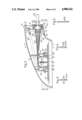
- FIG. 1 is a partially broken-away elevational view of a rear view mirror assembly in accordance with the invention, taken from the direction from which the mirror is viewed in use;
- FIG. 2 is a cross-sectional view taken on the line 2--2 in FIG. 1;
- FIGS. 3, 4 and 5 are cross-sectional views of one of the thrust-transmitting members of the rear view mirror assembly shown in FIG. 2, taken on the lines 3--3, 4--4, and 5--5 respectively.
- an exterior rear view mirror assembly has a casing 10 containing a reflective member 12 and mounted on a base 13 which has a peripheral flange 14, the edge of which is shaped to conform to the surface of a vehicle body (not shown), and a central boss 16 arranged to project beyond the edge of the flange 14 towards the interior of such a vehicle.
- the casing 10 is held in position on the base 13 by a pair of tension springs 20 and 22. If the casing 10 is subject to impact from the side from which the reflective member 12 is visible, it can pivot away from the impact about a point of engagement with its edge and a projection 24 on the base 14. Similarly, if the casing 10 is subject to impact from the opposite direction, it can pivot about a point of engagement of its edge with a projection 26 on the other side of the base 14.
- a cup-like support member 30 is secured to the interior of the casing 10 with an open end facing the back of the reflective member 12.
- the edge reasons of the support member 30 are flared outwardly so as to form a concave socket 32.
- the reflective member 12 is mounted on a mirror carrier 34 which has an annular flange 36 on the opposite side to the reflective member 12.
- the outer surface 38 of the flange 36 is of part-spherical shape and dimensioned to engage in the socket 32.
- a tension spring 40 extends from the centre of the support member 30 to the centre of the part of the surface of the mirror carrier 34 bounded by the flange 38 so as to hold the part spherical surface 38 in engagement with the socket 32.
- the mirror carrier 34 can pivot about two mutually perpendicular axes lying parallel to the surface of the reflective member 12 and intersecting at the centre of curvature of the part spherical surface 38, thereby allowing adjustment of the orientation of the reflective member 12 relative to the casing 10.
- the hollow boss 18 on the base 13 has a radially inwardly extending flange 42 on the end closer to the interior of the vehicle.
- a socket carrier 44 is dimensioned to be a sliding fit in the boss 18 and has a part-spherical concave socket portion 46 in which a part-spherical convex member 48 is received as a snap-fit.
- a compression spring 50 engages between the flange 42 and the socket carrier 44 so as to urge the latter towards the casing 10 but this movement is limited by projections 52 (FIG. 1) on the socket carrier 44 which engage in slots 53 in the side walls of the boss 18.
- the projections 52 preferably have chamfered faces directed towards the flange 42, the boss 18 and socket carrier 44 being made of a sufficiently resilient material to allow these projections 52 to be snapped into their respective slots 53 during assembly.
- the part-spherical convex member 48 has an operating lever 55 projecting into the interior of the vehicle. The opposite face thereof is substantially flat but has three recesses 54, 56 and 58 symmetrically spaced around its centre. Three pusher blades 60, 62 and 64 extend through respective holes in a bracket 66 mounted on the interior of the casing 10 adjacent to the base 14 so as to engage in respective recesses 54, 56 and 58 in the part spherical member 48.
- each of the blades 60, 62 and 64 carries a respective spherical formation 68 which is a snap-fit in a respective socket 70 on the back face of the mirror carrier 34, the three sockets 70 being symmetrically disposed around the centre of curvature of the part-spherical surface 38 of the annular projection 36 thereon.
- the pusher blades 60, 62 and 64 are of cross-shaped cross-section 60a as shown in FIG. 3. Between the part-spherical member 48 in the boss 18 and the support member 30, the three pusher blades 60, 62 and 64 are of T-shaped cross-section 60b as shown in FIG. 4. Consequently, the pusher blades resist bending in any direction transverse to their length in these regions. However, where the pusher blades 60, 62 and 64 pass through the walls of the support member 30, they are of flat strip-like cross-section 60c, as shown in FIG. 5, so as to be bendable in the direction of their minimum dimension. A respective guide channel 72, 74, 76, is provided where each of the pusher blades passes through the wall of the support member 30 so as to guide it through an angle of approximately 90 deg.
- each pusher blade 60, 62, 64 In use, when it is desired to adjust the orientation of the reflective member 12, the lever 52 is pivoted about the centre of the convex member 48, thus pushing on at least one of the pusher blades 60, 62 and 64 and allowing the other blade or blades to move towards the interior of the vehicle. The resulting movement of the other ends of the pusher blades 60, 62, and 64 produces a corresponding movement of the mirror carrier 34.
- the bendable central region of each pusher blade 60, 62, 64 allows the necessary flexing movement as it travels along its corresponding guide channel 72, 74, and 76.
- the spherical formations 68 on the ends of the pusher blades 60, 62 and 64 are not essential for the spherical formations 68 on the ends of the pusher blades 60, 62 and 64 to be a snap-fit in their respective sockets 70; it is sufficient for them to abut against the back of the mirror carrier. However, in this case, it is necessary either to replace the sockets 70 with sufficiently flared sockets to ensure that the pusher blades re-engage at their correct locations in the event of their becoming disengaged, or to provide guidance equivalent to the guidance provided by the bracket 66.
- the three pusher blades 60, 62 and 64 could be formed as a single integral plastics moulding connected to the mirror carrier 34 by integral plastic hinges.
Abstract
A remotely controlled rear view mirror assembly for a motor vehicle consists of a base adapted to be mounted on a vehicle body, a casing mouonted on the base and a reflective member mounted in the casing for angular movement about two mutually perpendicular axes. A control member is mounted on the base so as to engage with three elongate members each of which has two end portions of cross section adapted to resist bending about first and second mutually perpendicular transverse directions, interconnected by an intermediate portion having a cross-section adapted to permit bending in the first transverse direction. Guide means mounted in the casing are arranged to direct one end of each elongate member into abutment with a surface of the reflective member facing the interior of the casing, and to direct the other end of each elongate member through an opening in the casing facing the base so as to abut against the control member.
Description
This invention relates to a remotely controlled rear view mirror assembly for a motor vehicle of the type comprising a base adapted to be mounted on a vehicle body, a casing mounted on the base, a reflective member mounted in the casing for angular movement relative to the casing about two mutually perpendicular axes, a control member on the base and two thrust-transmitting units responsive to the control member for selectively applying a thrust to the reflective member at two locations, each of which is offset relative to a respective one of the two mutually perpendicular axes.
In a known mirror assembly of this type, each thrust-transmitting unit comprises a Bowden cable. However, this type of mirror is subject to a number of disadvantages. For example, if the Bowden cable is made of metal, it is subject to corrosion. In addition, if the casing is to be pivotable relative to the base so as to be displaceable when subject to impact, each cable has to be of sufficient length to permit such pivoting movement and there has to be sufficient space within the casing and/or the base to accommodate this additional length of cable.
According to the invention, in a rear view mirror assembly of the foregoing type, each thrust-transmitting unit comprises an elongate member having two end portions of cross section adapted to resist bending about first and second mutually perpendicular transverse directions, said end portions being interconnected by an intermediate portion having a cross-section adapted to permit bending in the first transverse direction, and guide means mounted in the casing and arranged to direct one end of each elongate member into abutment with a surface of the reflective member facing the interior of the casing, and to direct the other end of each elongate member through an opening in the casing facing the base so as to abut against the control member.
In one form of the invention, each elongate member comprises a strip of which the intermediate portion is flat and which has a flange extending from each end portion in said first transverse direction.
Preferably three thrust-transmitting units are arranged to engage with the reflective member at three locations symmetrically located about the point of intersection of the two axes about which the reflective member is moveable, and the control member comprises a part spherical member engaging in a complementary socket in the base and having a non-spherical surface against which an end each elongate member abuts so that angular movement of the control member in its socket causes corresponding angular movement of the reflective member.
An embodiment of the invention will now be described, by way of example, with reference to the accompanying drawings in which:
FIG. 1 is a partially broken-away elevational view of a rear view mirror assembly in accordance with the invention, taken from the direction from which the mirror is viewed in use;
FIG. 2 is a cross-sectional view taken on the line 2--2 in FIG. 1;
FIGS. 3, 4 and 5 are cross-sectional views of one of the thrust-transmitting members of the rear view mirror assembly shown in FIG. 2, taken on the lines 3--3, 4--4, and 5--5 respectively.
Referring to FIGS. 1 and 2, an exterior rear view mirror assembly has a casing 10 containing a reflective member 12 and mounted on a base 13 which has a peripheral flange 14, the edge of which is shaped to conform to the surface of a vehicle body (not shown), and a central boss 16 arranged to project beyond the edge of the flange 14 towards the interior of such a vehicle. The casing 10 is held in position on the base 13 by a pair of tension springs 20 and 22. If the casing 10 is subject to impact from the side from which the reflective member 12 is visible, it can pivot away from the impact about a point of engagement with its edge and a projection 24 on the base 14. Similarly, if the casing 10 is subject to impact from the opposite direction, it can pivot about a point of engagement of its edge with a projection 26 on the other side of the base 14.
Referring to FIG. 2, a cup-like support member 30 is secured to the interior of the casing 10 with an open end facing the back of the reflective member 12. The edge reasons of the support member 30 are flared outwardly so as to form a concave socket 32. The reflective member 12 is mounted on a mirror carrier 34 which has an annular flange 36 on the opposite side to the reflective member 12. The outer surface 38 of the flange 36 is of part-spherical shape and dimensioned to engage in the socket 32. A tension spring 40 extends from the centre of the support member 30 to the centre of the part of the surface of the mirror carrier 34 bounded by the flange 38 so as to hold the part spherical surface 38 in engagement with the socket 32. Consequently the mirror carrier 34 can pivot about two mutually perpendicular axes lying parallel to the surface of the reflective member 12 and intersecting at the centre of curvature of the part spherical surface 38, thereby allowing adjustment of the orientation of the reflective member 12 relative to the casing 10.
The hollow boss 18 on the base 13 has a radially inwardly extending flange 42 on the end closer to the interior of the vehicle. A socket carrier 44 is dimensioned to be a sliding fit in the boss 18 and has a part-spherical concave socket portion 46 in which a part-spherical convex member 48 is received as a snap-fit. A compression spring 50 engages between the flange 42 and the socket carrier 44 so as to urge the latter towards the casing 10 but this movement is limited by projections 52 (FIG. 1) on the socket carrier 44 which engage in slots 53 in the side walls of the boss 18. The projections 52 preferably have chamfered faces directed towards the flange 42, the boss 18 and socket carrier 44 being made of a sufficiently resilient material to allow these projections 52 to be snapped into their respective slots 53 during assembly.
The part-spherical convex member 48 has an operating lever 55 projecting into the interior of the vehicle. The opposite face thereof is substantially flat but has three recesses 54, 56 and 58 symmetrically spaced around its centre. Three pusher blades 60, 62 and 64 extend through respective holes in a bracket 66 mounted on the interior of the casing 10 adjacent to the base 14 so as to engage in respective recesses 54, 56 and 58 in the part spherical member 48. The other end of each of the blades 60, 62 and 64 carries a respective spherical formation 68 which is a snap-fit in a respective socket 70 on the back face of the mirror carrier 34, the three sockets 70 being symmetrically disposed around the centre of curvature of the part-spherical surface 38 of the annular projection 36 thereon.
In the vicinity of the mirror carrier 34, the pusher blades 60, 62 and 64 are of cross-shaped cross-section 60a as shown in FIG. 3. Between the part-spherical member 48 in the boss 18 and the support member 30, the three pusher blades 60, 62 and 64 are of T-shaped cross-section 60b as shown in FIG. 4. Consequently, the pusher blades resist bending in any direction transverse to their length in these regions. However, where the pusher blades 60, 62 and 64 pass through the walls of the support member 30, they are of flat strip-like cross-section 60c, as shown in FIG. 5, so as to be bendable in the direction of their minimum dimension. A respective guide channel 72, 74, 76, is provided where each of the pusher blades passes through the wall of the support member 30 so as to guide it through an angle of approximately 90 deg.
In use, when it is desired to adjust the orientation of the reflective member 12, the lever 52 is pivoted about the centre of the convex member 48, thus pushing on at least one of the pusher blades 60, 62 and 64 and allowing the other blade or blades to move towards the interior of the vehicle. The resulting movement of the other ends of the pusher blades 60, 62, and 64 produces a corresponding movement of the mirror carrier 34. The bendable central region of each pusher blade 60, 62, 64 allows the necessary flexing movement as it travels along its corresponding guide channel 72, 74, and 76.
If the casing 10 is displaced from its normal position as a result of impact, the ends of the pusher blades 60, 62 and 64 disengage from their respective recesses 54, 56 and 58 in the part-spherical member 48 and reingage therein when the casing 10 is returned to its normal position. Normally there will be sufficient friction between the convex member 48 and its socket 46 to retain the lever 55 in its preset position; however, if it has moved from such position, the pusher blades 60, 62 and 64 restore it to the position which it occupied at the time of disengagement, rather than causing inadvertent alteration of the orientation of the mirror carrier 34, because the friction between the part-spherical surface 38 thereon and the flange 32 is greater than the friction between the part-spherical member 48 carrying the operating lever 55 and its socket 46.
It is not essential for the spherical formations 68 on the ends of the pusher blades 60, 62 and 64 to be a snap-fit in their respective sockets 70; it is sufficient for them to abut against the back of the mirror carrier. However, in this case, it is necessary either to replace the sockets 70 with sufficiently flared sockets to ensure that the pusher blades re-engage at their correct locations in the event of their becoming disengaged, or to provide guidance equivalent to the guidance provided by the bracket 66.
As a further alternative, the three pusher blades 60, 62 and 64 could be formed as a single integral plastics moulding connected to the mirror carrier 34 by integral plastic hinges.
Claims (10)
1. A remotely controlled rear view mirror assembly for a motor vehicle comprising a base adapted to be mounted on a vehicle body, a casing mounted on the base, a reflective member mounted in the casing for angular movement relative to the casing about two mutually perpendicular axes, a control member on the base and two thrust-transmitting units responsive to the control member for selectively applying a thrust to the reflective member at two locations, each of which is offset relative to a respective one of the two mutually perpendicular axes, wherein each thrust-transmitting unit comprises guide means mounted in the casing and an elongate member slidably mounted in the guide means, the elongate member having two end portions of cross section adapted to resist bending about first and second mutually perpendicular transverse directions, said end portions being interconnected by an intermediate portion having a cross-section adapted to permit bending in the first transverse direction, and the guide means being arranged to direct one end of each elongate member into abutment with a surface of the reflective member facing the interior of the casing and to direct the other end of each elongate member through an opening in the casing facing the base so as to abut against the control member.
2. A rear view mirror assembly according to claim 1, wherein each elongate member comprises a strip of which the intermediate portion is flat and which has a flange extending from each end portion in said first transverse direction.
3. A rear view mirror assembly according to claim 2, wherein three- thrust-transmitting units are arranged to engage with the reflective member at three locations symmetrically located about the point of intersection of the two axes about which the reflective member is moveable, and wherein the control member comprises a part spherical member engaging in a complementary socket in the base and having a non-spherical surface against which an end of each elongate member abuts so that angular movement of the control member in its socket causes corresponding angular movement of the reflective member.
4. A rear view mirror assembly according to claim 3, wherein the reflective member has a convex part-spherical flange centered on the point of intersection of the axes about which it is moveable, said flange being held in engagement with a concave part-spherical socket in the casing by a tension spring.
5. A rear view mirror assembly according to claim 4, wherein the socket for the control member is mounted on resilient means for urging the control member into engagement with the thrust-transmitting units.
6. A rear view mirror assembly according to claim 3, wherein the socket for the control member is mounted on resilient means for urging the control member into engagement with the thrust-transmitting units.
7. A rear view mirror assembly according to claim 1, wherein three thrust-transmitting units are arranged to engage with the reflective member at three locations symmetrically located about the point of intersection of the two axes about which the reflective member is moveable, .and the control member comprises a part spherical member engaging in a complementary socket in the base and having a non-spherical surface against which an end each elongate member abuts so that angular movement of the control member in its socket causes corresponding angular movement of the reflective member.
8. A rear view mirror assembly according to claim 7, wherein the reflective member has a convex part-spherical flange centred on the point of intersection of the axes about which it is moveable, said flange being held in engagement with a concave part-spherical socket in the casing by a tension spring.
9. A rear view mirror assembly according to claim 8, wherein the socket for the control member is mounted on resilient means for urging the control member into engagement with the thrust-transmitting units.
10. A rear view mirror assembly according to claim 7, wherein the socket for the control member is mounted on resilient means for urging the control member into engagement with the thrust-transmitting units.
Applications Claiming Priority (2)
| Application Number | Priority Date | Filing Date | Title |
|---|---|---|---|
| GB8802060 | 1988-01-29 | ||
| GB888802060A GB8802060D0 (en) | 1988-01-29 | 1988-01-29 | Remotely controlled rear view mirror |
Publications (1)
| Publication Number | Publication Date |
|---|---|
| US4900142A true US4900142A (en) | 1990-02-13 |
Family
ID=10630766
Family Applications (1)
| Application Number | Title | Priority Date | Filing Date |
|---|---|---|---|
| US07/301,660 Expired - Fee Related US4900142A (en) | 1988-01-29 | 1989-01-25 | Remotely controlled rear view mirror |
Country Status (7)
| Country | Link |
|---|---|
| US (1) | US4900142A (en) |
| EP (1) | EP0326264A1 (en) |
| JP (1) | JPH01226451A (en) |
| KR (1) | KR890011729A (en) |
| CN (1) | CN1034507A (en) |
| AU (1) | AU2879189A (en) |
| GB (1) | GB8802060D0 (en) |
Cited By (1)
| Publication number | Priority date | Publication date | Assignee | Title |
|---|---|---|---|---|
| US6555222B1 (en) | 2000-01-13 | 2003-04-29 | Schefenacker Vision Systems France Sa | Reinforced polypropylene mirror assembly and process for making the same |
Families Citing this family (4)
| Publication number | Priority date | Publication date | Assignee | Title |
|---|---|---|---|---|
| IT1263120B (en) * | 1992-05-05 | 1996-07-30 | Gilardini Spa | REAR-VIEW MIRROR FOR A VEHICLE EQUIPPED WITH A SUPPORT AND ORIENTATION DEVICE OF A REFLECTIVE SHEET OF THE PERFECT TYPE |
| US5477390A (en) * | 1993-08-16 | 1995-12-19 | Lowell Engineering Corp. | Mirror assembly powered into rearwardly folded position against reversing spring bias |
| ES2189660B1 (en) * | 2001-08-02 | 2004-10-16 | Fico Mirrors, S.A. | OUTDOOR REAR VIEW MIRROR FOR MOTOR VEHICLES. |
| DE102017200381A1 (en) * | 2017-01-11 | 2018-07-12 | Ford Global Technologies, Llc | mirror device |
Citations (5)
| Publication number | Priority date | Publication date | Assignee | Title |
|---|---|---|---|---|
| EP0060362A1 (en) * | 1981-03-12 | 1982-09-22 | Surrey Steel Components Limited | Adjustable rear view mirrors |
| DE3416656A1 (en) * | 1984-05-05 | 1985-11-14 | Reitter & Schefenacker Kg, 7300 Esslingen | Outside rear view mirror for vehicles |
| US4678295A (en) * | 1985-04-05 | 1987-07-07 | Magna International Inc | Memory positioning system for remote control rear-view mirror |
| EP0269081A1 (en) * | 1986-11-26 | 1988-06-01 | Murakami Kaimeido Co., Ltd | Supporting device of a mirror element for a rearview mirror |
| US4768871A (en) * | 1985-06-29 | 1988-09-06 | Bernhard Mittelhauser | Mirror for motor vehicles |
-
1988
- 1988-01-29 GB GB888802060A patent/GB8802060D0/en active Pending
-
1989
- 1989-01-17 EP EP89300395A patent/EP0326264A1/en not_active Withdrawn
- 1989-01-25 AU AU28791/89A patent/AU2879189A/en not_active Abandoned
- 1989-01-25 US US07/301,660 patent/US4900142A/en not_active Expired - Fee Related
- 1989-01-28 CN CN89100605A patent/CN1034507A/en active Pending
- 1989-01-28 KR KR1019890000970A patent/KR890011729A/en not_active Application Discontinuation
- 1989-01-30 JP JP1020678A patent/JPH01226451A/en active Pending
Patent Citations (5)
| Publication number | Priority date | Publication date | Assignee | Title |
|---|---|---|---|---|
| EP0060362A1 (en) * | 1981-03-12 | 1982-09-22 | Surrey Steel Components Limited | Adjustable rear view mirrors |
| DE3416656A1 (en) * | 1984-05-05 | 1985-11-14 | Reitter & Schefenacker Kg, 7300 Esslingen | Outside rear view mirror for vehicles |
| US4678295A (en) * | 1985-04-05 | 1987-07-07 | Magna International Inc | Memory positioning system for remote control rear-view mirror |
| US4768871A (en) * | 1985-06-29 | 1988-09-06 | Bernhard Mittelhauser | Mirror for motor vehicles |
| EP0269081A1 (en) * | 1986-11-26 | 1988-06-01 | Murakami Kaimeido Co., Ltd | Supporting device of a mirror element for a rearview mirror |
Cited By (1)
| Publication number | Priority date | Publication date | Assignee | Title |
|---|---|---|---|---|
| US6555222B1 (en) | 2000-01-13 | 2003-04-29 | Schefenacker Vision Systems France Sa | Reinforced polypropylene mirror assembly and process for making the same |
Also Published As
| Publication number | Publication date |
|---|---|
| JPH01226451A (en) | 1989-09-11 |
| EP0326264A1 (en) | 1989-08-02 |
| KR890011729A (en) | 1989-08-22 |
| AU2879189A (en) | 1989-08-03 |
| CN1034507A (en) | 1989-08-09 |
| GB8802060D0 (en) | 1988-02-24 |
Similar Documents
| Publication | Publication Date | Title |
|---|---|---|
| US5746651A (en) | Eyeball outlet assembly | |
| EP0511203B1 (en) | Automotive rearview mirror assembly | |
| US4903541A (en) | Anchoring and adjusting assembly for a control cable | |
| US5432987A (en) | Central lock for multi-point safety belts | |
| EP0220010A2 (en) | Exterior rear view mirrors for vehicles | |
| CA1114351A (en) | Dual spool positive drive retractor | |
| US6168279B1 (en) | Pivot support for adjustable rearview mirror | |
| US4900142A (en) | Remotely controlled rear view mirror | |
| US4867409A (en) | Breakaway mirrors | |
| EP0290233B1 (en) | Breakaway mirror spring means | |
| GB2136494A (en) | Remote control rearview mirror and pivot | |
| US4040576A (en) | Retractor lock and pawl saddle therefor | |
| US6270227B1 (en) | Remote-controlled mirror apparatus for vehicles | |
| US4919525A (en) | Break-away mirror mechanism | |
| US4830327A (en) | Rear vision mirror adjusting means | |
| EP0177458A1 (en) | External rear-view mirror for motor vehicles | |
| US4661007A (en) | Corner guide assembly | |
| JPH0195957A (en) | Rotary joint | |
| CN110087950B (en) | Ball rack assembly for vehicle | |
| US3933058A (en) | Universal support for vehicle mirror | |
| EP0206758B1 (en) | Vehicle door mirrors | |
| EP0064335B1 (en) | Rear-view mirror for motor vehicles | |
| EP0064815B1 (en) | Remotely-controlled rear-view mirror | |
| GB1578950A (en) | Rear view mirror assembly | |
| EP2077205A2 (en) | A multi-axis pivoting detent joint assembly for an exterior vehicle mirror |
Legal Events
| Date | Code | Title | Description |
|---|---|---|---|
| AS | Assignment |
Owner name: BRITAX (GECO) SA, , A CORP., FRANCE Free format text: ASSIGNMENT OF ASSIGNORS INTEREST.;ASSIGNOR:DUROUX, BERNARD;REEL/FRAME:005034/0535 Effective date: 19881222 |
|
| REMI | Maintenance fee reminder mailed | ||
| LAPS | Lapse for failure to pay maintenance fees | ||
| FP | Lapsed due to failure to pay maintenance fee |
Effective date: 19940213 |
|
| STCH | Information on status: patent discontinuation |
Free format text: PATENT EXPIRED DUE TO NONPAYMENT OF MAINTENANCE FEES UNDER 37 CFR 1.362 |