US4899981A - In-run cleanable orifice trap - Google Patents
In-run cleanable orifice trap Download PDFInfo
- Publication number
- US4899981A US4899981A US06/809,603 US80960385A US4899981A US 4899981 A US4899981 A US 4899981A US 80960385 A US80960385 A US 80960385A US 4899981 A US4899981 A US 4899981A
- Authority
- US
- United States
- Prior art keywords
- stopper member
- orifice
- blow
- flow opening
- restriction orifice
- Prior art date
- Legal status (The legal status is an assumption and is not a legal conclusion. Google has not performed a legal analysis and makes no representation as to the accuracy of the status listed.)
- Expired - Fee Related
Links
Images

Classifications
-
- F—MECHANICAL ENGINEERING; LIGHTING; HEATING; WEAPONS; BLASTING
- F16—ENGINEERING ELEMENTS AND UNITS; GENERAL MEASURES FOR PRODUCING AND MAINTAINING EFFECTIVE FUNCTIONING OF MACHINES OR INSTALLATIONS; THERMAL INSULATION IN GENERAL
- F16K—VALVES; TAPS; COCKS; ACTUATING-FLOATS; DEVICES FOR VENTING OR AERATING
- F16K5/00—Plug valves; Taps or cocks comprising only cut-off apparatus having at least one of the sealing faces shaped as a more or less complete surface of a solid of revolution, the opening and closing movement being predominantly rotary
- F16K5/06—Plug valves; Taps or cocks comprising only cut-off apparatus having at least one of the sealing faces shaped as a more or less complete surface of a solid of revolution, the opening and closing movement being predominantly rotary with plugs having spherical surfaces; Packings therefor
- F16K5/0605—Plug valves; Taps or cocks comprising only cut-off apparatus having at least one of the sealing faces shaped as a more or less complete surface of a solid of revolution, the opening and closing movement being predominantly rotary with plugs having spherical surfaces; Packings therefor with particular plug arrangements, e.g. particular shape or built-in means
Definitions
- the invention relates to an assembly for removing liquid from a pressurized gaseous system. Particular applications are the removal of condensate from pressurized steam lines and water from pressurized air lines.
- the assembly is characterized as an orifice steam trap or liquid drainer.
- An assembly for removing liquid from a pressurized gaseous system, such as condensate from a steam line contains a rotatable stopper member with a restriction orifice.
- the restriction orifice in the stopper member provides for removal of condensate with only a minor, controlled loss of steam.
- the stopper member is rotatable so that the orifice can be rotated 180° to the pressure flow, thus allowing the pressure to blow out any trash that becomes lodged on or in the orifice without having to remove the assembly from service for cleaning.
- a preferred embodiment includes a much larger blow-down port in the stopper member in addition to the restriction orifice. The stopper member can be rotated so that the blow-down port is in the line of flow, thus permitting the removal of trash and excess liquid that may accumulate in the line.
- FIG. 1 is a side sectional view of an assembly with a spherical stopper member with the restriction orifice positioned in normal trap operating position.
- FIG. 2 is a side sectional view where the spherical stopper member of FIG. 1 has been rotated about 90° to the blow-down position permitting removal of trash or excess liquid.
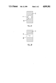
- FIGS. 3a and 3b are side sectional views of a cylindrical stopper member as an alternative embodiment to the spherical stopper member of FIGS. 1 and 2.
- FIG. 1 illustrates an assembly embodying the invention which provides for liquid discharge from a pressurized gaseous system such as a steam line.
- the upstream flow opening 1 is connected to the pressurized gaseous system and the arrow indicates the pressure flow.
- Downstream flow opening 2 can be open to the atmosphere or connected to a convenient discharge line.
- Stopper member 3 illustrated is a spherical element, similar in many respects to a ball valve.
- the stopper member 3 has a restriction orifice 4 which provides substantially all communication between the upstream pressure flow and downstream discharge flow.
- the stopper member can also be of various other configurations including a straight or truncated cylinder (see FIGS. 3a and 3b) and a plate or disk.
- the stopper member may be made from any suitable material for the environment contemplated.
- the restriction orifice permits liquid to flow through along with a controlled loss of gas.
- the diameter or the orifice is determined by the pressure differential ( ⁇ p) between the upstream and downstream pressure within the particular gas system and by the liquid load.
- the purpose of the restriction orifice is to minimize the loss of gas while at the same time effecting desired liquid discharge. For a given liquid load, at lower ⁇ p the restriction orifice must be of a larger diameter whereas at higher ⁇ p the diameter should be reduced to minimize gas loss.
- the stopper member 3 is rotatably mounted in housing means 5 with gaskets 6 disposed therebetween to provide an appropriate seal and to prevent excessive loss of gas. It is apparent from FIG. 1 that should trash clog the restriction orifice, the stopper member can be readily rotated 180° by handle 7, thus permitting the gas pressure to blow out such trash. This facilitates cleaning of the restriction orifice without need of disassembly and without tasking the line out of service.
- the assembly can be characterized as an In-Run Cleanable Orifice (IRCO) trap.
- IRCO In-Run Cleanable Orifice
- a preferred embodiment of the invention includes blow-down means associated with the stopper member for trash and excess liquid blow-off.
- the stopper member can be rotated to a position providing communication between the upstream flow opening and downstream flow opening through the blow-down means, thus permitting accumulated trash and excess liquid to be blown off.
- the blow-down means allows removal of the large volume of liquid that forms when a steam system is warmed up or an air system is upset. If the stopper member is a plate or disk configuration, rotating the member to a position substantially parallel to the pressure flow provides such blow-down means. If the stopper member is a sphere or cylinder, blow-down means may comprise channels or grooves in the sides of the member or a port extending through the member.
- FIG. 1 a preferred blow-down means is shown as blow-down port 8 which extends through spherical stopper member 3 substantially at right angles to, and intersecting with, the restriction orifice.
- the blow-down port 8 is substantially larger than restriction orifice 4.
- FIG. 1 shows the stopper member 3 in a normal operating position wherein the restriction orifice 4 provides communication between the upstream and downstream flow.
- the plug member 3 has been rotated about 90° whereby blow-down port 8 provides substantially increased communication between the upstream and downstream flow to permit accumulated trash and excess liquid to pass through.
- the stopper member can be rotated an additional 90°, thereby reversing the position shown in FIG. 1. In this manner, the reversing of pressure forces serves to blow-out materials which have deposited within the orifice.
- FIG. 1 offers an additional advantage.
- blow-down port 8 intersecting restriction orifice 4
- blow-down port 8 serves as an expansion chamber and that restriction orifice 4 is actually two orifices in series. This arrangement reduces erosion of the restriction orifice.
- the assembly of this invention can be utilized for the discharge of liquid or condensate from any pressurized gaseous systems, including steam lines, compressed air system, and the like. Many other modifications, variations and uses of the present invention are possible in light of the above teachings.
Landscapes
- Engineering & Computer Science (AREA)
- General Engineering & Computer Science (AREA)
- Mechanical Engineering (AREA)
- Details Of Valves (AREA)
Abstract
Description
Claims (3)
Priority Applications (1)
| Application Number | Priority Date | Filing Date | Title |
|---|---|---|---|
| US06/809,603 US4899981A (en) | 1985-12-16 | 1985-12-16 | In-run cleanable orifice trap |
Applications Claiming Priority (1)
| Application Number | Priority Date | Filing Date | Title |
|---|---|---|---|
| US06/809,603 US4899981A (en) | 1985-12-16 | 1985-12-16 | In-run cleanable orifice trap |
Publications (1)
| Publication Number | Publication Date |
|---|---|
| US4899981A true US4899981A (en) | 1990-02-13 |
Family
ID=25201751
Family Applications (1)
| Application Number | Title | Priority Date | Filing Date |
|---|---|---|---|
| US06/809,603 Expired - Fee Related US4899981A (en) | 1985-12-16 | 1985-12-16 | In-run cleanable orifice trap |
Country Status (1)
| Country | Link |
|---|---|
| US (1) | US4899981A (en) |
Cited By (10)
| Publication number | Priority date | Publication date | Assignee | Title |
|---|---|---|---|---|
| EP0482904A1 (en) * | 1990-10-23 | 1992-04-29 | Neil Allen | Flow restrictor |
| US5305986A (en) * | 1993-03-31 | 1994-04-26 | Hunt Kevin F | Fluid control valve |
| US5947157A (en) * | 1995-12-11 | 1999-09-07 | Kindersley; Peter | Throttling device and element |
| US5988155A (en) * | 1995-09-12 | 1999-11-23 | Garceau; William J. | Fluid flow valves and cooking machine control systems utilizing such valves |
| KR100794727B1 (en) * | 2006-12-29 | 2008-01-21 | 두산중공업 주식회사 | Pipe line structure for steam supply |
| CN102359695A (en) * | 2011-09-26 | 2012-02-22 | 奇瑞汽车股份有限公司 | Hydraulic power-assisted steering oil return line and method for reducing noises thereof |
| CN107208813A (en) * | 2015-02-18 | 2017-09-26 | 威兰有限公司 | There is the multiport ball valve of induced flow in spheroid chamber |
| US20190085998A1 (en) * | 2017-09-20 | 2019-03-21 | Copreci, S. Coop. | Electromagnetic Gas Valve, Gas Regulating Valve and Gas Cooking Appliance |
| RU2700055C1 (en) * | 2018-05-17 | 2019-09-12 | Общество с ограниченной ответственностью "Газпром трансгаз Ухта" | Method for removal of condensate from spherical cavity of pipeline valves and device for implementation thereof |
| RU218750U1 (en) * | 2022-12-22 | 2023-06-08 | Общество с ограниченной ответственностью "Газпром трансгаз Ухта" | TANK FOR COLLECTING CONDENSATE DURING GAS BLEEDING FROM THE BALL CAVITY OF PIPELINE FITTINGS |
Citations (3)
| Publication number | Priority date | Publication date | Assignee | Title |
|---|---|---|---|---|
| DE2531809A1 (en) * | 1974-07-17 | 1976-01-29 | Fuji Photo Film Co Ltd | Valve with spherical closure member - having main fluid passage and subsidiary passages at angle thereto |
| US4130128A (en) * | 1974-07-17 | 1978-12-19 | Fuji Photo Film Co., Ltd. | Ball valve with orifice |
| SU742662A1 (en) * | 1976-04-23 | 1980-06-25 | Алма-Атинский Государственный Проектный Институт "Сантехпроект" Госстроя Ссср | Adjustable throttle |
-
1985
- 1985-12-16 US US06/809,603 patent/US4899981A/en not_active Expired - Fee Related
Patent Citations (3)
| Publication number | Priority date | Publication date | Assignee | Title |
|---|---|---|---|---|
| DE2531809A1 (en) * | 1974-07-17 | 1976-01-29 | Fuji Photo Film Co Ltd | Valve with spherical closure member - having main fluid passage and subsidiary passages at angle thereto |
| US4130128A (en) * | 1974-07-17 | 1978-12-19 | Fuji Photo Film Co., Ltd. | Ball valve with orifice |
| SU742662A1 (en) * | 1976-04-23 | 1980-06-25 | Алма-Атинский Государственный Проектный Институт "Сантехпроект" Госстроя Ссср | Adjustable throttle |
Non-Patent Citations (4)
| Title |
|---|
| Jamesbury Corp. Bulletin 212, "Type 1000 Screwed End Ball Valves 1/4 to 2"". |
| Jamesbury Corp. Bulletin 212, Type 1000 Screwed End Ball Valves to 2 . * |
| W K M Valve Division, Houston, Texas, Bulletin B 165M, Installation, Operation and Maintenance of W K M DynaSeal 310 Ball Valves . * |
| W-K-M Valve Division, Houston, Texas, Bulletin B-165M, "Installation, Operation and Maintenance of W-K-M DynaSeal 310 Ball Valves". |
Cited By (13)
| Publication number | Priority date | Publication date | Assignee | Title |
|---|---|---|---|---|
| EP0482904A1 (en) * | 1990-10-23 | 1992-04-29 | Neil Allen | Flow restrictor |
| US5305986A (en) * | 1993-03-31 | 1994-04-26 | Hunt Kevin F | Fluid control valve |
| WO1994023227A1 (en) * | 1993-03-31 | 1994-10-13 | Hunt Kevin F | Fluid control valve |
| US5988155A (en) * | 1995-09-12 | 1999-11-23 | Garceau; William J. | Fluid flow valves and cooking machine control systems utilizing such valves |
| US5947157A (en) * | 1995-12-11 | 1999-09-07 | Kindersley; Peter | Throttling device and element |
| KR100794727B1 (en) * | 2006-12-29 | 2008-01-21 | 두산중공업 주식회사 | Pipe line structure for steam supply |
| CN102359695A (en) * | 2011-09-26 | 2012-02-22 | 奇瑞汽车股份有限公司 | Hydraulic power-assisted steering oil return line and method for reducing noises thereof |
| CN107208813A (en) * | 2015-02-18 | 2017-09-26 | 威兰有限公司 | There is the multiport ball valve of induced flow in spheroid chamber |
| US20190085998A1 (en) * | 2017-09-20 | 2019-03-21 | Copreci, S. Coop. | Electromagnetic Gas Valve, Gas Regulating Valve and Gas Cooking Appliance |
| US10801639B2 (en) * | 2017-09-20 | 2020-10-13 | Copreci, S. Coop. | Electromagnetic gas valve, gas regulating valve and gas cooking appliance |
| RU2700055C1 (en) * | 2018-05-17 | 2019-09-12 | Общество с ограниченной ответственностью "Газпром трансгаз Ухта" | Method for removal of condensate from spherical cavity of pipeline valves and device for implementation thereof |
| RU218750U1 (en) * | 2022-12-22 | 2023-06-08 | Общество с ограниченной ответственностью "Газпром трансгаз Ухта" | TANK FOR COLLECTING CONDENSATE DURING GAS BLEEDING FROM THE BALL CAVITY OF PIPELINE FITTINGS |
| RU218847U1 (en) * | 2023-04-17 | 2023-06-14 | Общество с ограниченной ответственностью "Газпром трансгаз Чайковский" | Device for removing liquid and solid substances from the drainage cavity of pipeline fittings |
Similar Documents
| Publication | Publication Date | Title |
|---|---|---|
| US4690169A (en) | Combined shut off and check valve | |
| US4649952A (en) | Combined shut off and check valve | |
| US4899981A (en) | In-run cleanable orifice trap | |
| US4700732A (en) | Faucet drain apparatus | |
| US4171209A (en) | Apparatus for removing condensate from steam lines, and the like | |
| US4632757A (en) | Filters cleanable by reverse flushing | |
| US3426797A (en) | Multiple orifice valve | |
| US3679060A (en) | Duplex strainer construction | |
| US4852610A (en) | Valve and arrangement for fire suppression water sprinkler system | |
| US3715870A (en) | Orifice and filter assembly | |
| US5370154A (en) | Rotary control valve with variable area orifice | |
| US4702269A (en) | By-pass valve | |
| EP0520997B1 (en) | A ball valve | |
| JPH0658435A (en) | Unit aggregate device for controlling fluid pressure and fluid capacity of fluidized medium | |
| KR100460935B1 (en) | Condensate discharge device | |
| US5042518A (en) | Liquid elimination system for vacuum line | |
| US5244011A (en) | Control valve | |
| US4995423A (en) | Valve and arrangement for fire suppression water sprinkler system | |
| US3406715A (en) | Drain valve | |
| US6341624B1 (en) | Valve for cryogenic fluid | |
| US4195658A (en) | Resettable safety valve | |
| US5036883A (en) | Valve and arrangement for fire suppression water sprinkler system | |
| US2690931A (en) | Diverting valve for pneumatic conveying apparatus | |
| US4776730A (en) | System and method for managing fly ash transport and valve for use therein | |
| US4526199A (en) | Valve for throttling fluid |
Legal Events
| Date | Code | Title | Description |
|---|---|---|---|
| AS | Assignment |
Owner name: ALLIED CORPORATION, COLUMBIA ROAD AND PARK AVENUE, Free format text: ASSIGNMENT OF ASSIGNORS INTEREST.;ASSIGNOR:THOMAS, ROY S. JR.;REEL/FRAME:004496/0768 Effective date: 19851211 |
|
| AS | Assignment |
Owner name: ALLIED-SIGNAL INC., A CORP. OF DE Free format text: MERGER;ASSIGNORS:ALLIED CORPORATION, A CORP. OF NY;TORREA CORPORATION, THE, A CORP. OF NY;SIGNAL COMPANIES, INC., THE, A CORP. OF DE;REEL/FRAME:004809/0501 Effective date: 19870930 |
|
| FEPP | Fee payment procedure |
Free format text: PAYOR NUMBER ASSIGNED (ORIGINAL EVENT CODE: ASPN); ENTITY STATUS OF PATENT OWNER: LARGE ENTITY |
|
| FPAY | Fee payment |
Year of fee payment: 4 |
|
| FEPP | Fee payment procedure |
Free format text: PAYER NUMBER DE-ASSIGNED (ORIGINAL EVENT CODE: RMPN); ENTITY STATUS OF PATENT OWNER: LARGE ENTITY |
|
| REMI | Maintenance fee reminder mailed | ||
| LAPS | Lapse for failure to pay maintenance fees | ||
| FP | Lapsed due to failure to pay maintenance fee |
Effective date: 19980218 |
|
| STCH | Information on status: patent discontinuation |
Free format text: PATENT EXPIRED DUE TO NONPAYMENT OF MAINTENANCE FEES UNDER 37 CFR 1.362 |