US4899960A - Decompression panel for aircraft partition - Google Patents
Decompression panel for aircraft partition Download PDFInfo
- Publication number
- US4899960A US4899960A US07/191,412 US19141288A US4899960A US 4899960 A US4899960 A US 4899960A US 19141288 A US19141288 A US 19141288A US 4899960 A US4899960 A US 4899960A
- Authority
- US
- United States
- Prior art keywords
- decompression
- panel
- opening
- frame
- partition
- Prior art date
- Legal status (The legal status is an assumption and is not a legal conclusion. Google has not performed a legal analysis and makes no representation as to the accuracy of the status listed.)
- Expired - Fee Related
Links
Images

Classifications
-
- B—PERFORMING OPERATIONS; TRANSPORTING
- B64—AIRCRAFT; AVIATION; COSMONAUTICS
- B64C—AEROPLANES; HELICOPTERS
- B64C1/00—Fuselages; Constructional features common to fuselages, wings, stabilising surfaces or the like
- B64C1/18—Floors
-
- B—PERFORMING OPERATIONS; TRANSPORTING
- B64—AIRCRAFT; AVIATION; COSMONAUTICS
- B64C—AEROPLANES; HELICOPTERS
- B64C1/00—Fuselages; Constructional features common to fuselages, wings, stabilising surfaces or the like
- B64C2001/009—Fuselages; Constructional features common to fuselages, wings, stabilising surfaces or the like comprising decompression panels or valves for pressure equalisation in fuselages or floors
-
- Y—GENERAL TAGGING OF NEW TECHNOLOGICAL DEVELOPMENTS; GENERAL TAGGING OF CROSS-SECTIONAL TECHNOLOGIES SPANNING OVER SEVERAL SECTIONS OF THE IPC; TECHNICAL SUBJECTS COVERED BY FORMER USPC CROSS-REFERENCE ART COLLECTIONS [XRACs] AND DIGESTS
- Y10—TECHNICAL SUBJECTS COVERED BY FORMER USPC
- Y10T—TECHNICAL SUBJECTS COVERED BY FORMER US CLASSIFICATION
- Y10T137/00—Fluid handling
- Y10T137/1624—Destructible or deformable element controlled
- Y10T137/1632—Destructible element
- Y10T137/1782—Frangible element returns pressure responsive valve
-
- Y—GENERAL TAGGING OF NEW TECHNOLOGICAL DEVELOPMENTS; GENERAL TAGGING OF CROSS-SECTIONAL TECHNOLOGIES SPANNING OVER SEVERAL SECTIONS OF THE IPC; TECHNICAL SUBJECTS COVERED BY FORMER USPC CROSS-REFERENCE ART COLLECTIONS [XRACs] AND DIGESTS
- Y10—TECHNICAL SUBJECTS COVERED BY FORMER USPC
- Y10T—TECHNICAL SUBJECTS COVERED BY FORMER US CLASSIFICATION
- Y10T292/00—Closure fasteners
- Y10T292/08—Bolts
- Y10T292/0801—Multiple
- Y10T292/082—Spring arm
-
- Y—GENERAL TAGGING OF NEW TECHNOLOGICAL DEVELOPMENTS; GENERAL TAGGING OF CROSS-SECTIONAL TECHNOLOGIES SPANNING OVER SEVERAL SECTIONS OF THE IPC; TECHNICAL SUBJECTS COVERED BY FORMER USPC CROSS-REFERENCE ART COLLECTIONS [XRACs] AND DIGESTS
- Y10—TECHNICAL SUBJECTS COVERED BY FORMER USPC
- Y10T—TECHNICAL SUBJECTS COVERED BY FORMER US CLASSIFICATION
- Y10T292/00—Closure fasteners
- Y10T292/23—Cross bars
Definitions
- the present invention relates to a decompression panel for use in walls or intermediate bottoms in aircraft, all being hereinafter referred to as partitions.
- An aircraft is often subdivided, for example, into a passenger compartment and a freight or cargo compartment(s). More particularly then, the invention relates to a decompression panel of the kind referred to above wherein a definite sealing is provided for normal situations, panels being insertable in a relatively large decompression opening.
- the panel is presumed to be of a sandwich construction, being held in that opening by, say, uniformly distributed holding and clamping structures or the like.
- a sudden decompression of an explosive nature may occur in aircraft, particularly when flying at an altitude in which the pressure is significantly reduced as compared with ordinary surface pressure.
- Aircraft have to be designed, as far as the fuselage is concerned, to operate in a pressurized condition, in that the air pressure inside is similar to the pressure near the earth's surface. Hence, in higher altitudes there is a very high pressure differential between the interior of the fuselage and the external environment.
- Known commercial aircraft are usually provided with a passenger compartment as well as with a cargo compartment separated from each other through bottom sealing structure such as appropriate partitions, walls, etc. It may be of advantage to subdivide and to seal the cargo space through additional partitions.
- an explosive decompression occurs in one, for example, the cargo compartment, it is desirable to prevent the immediate propagation of that explosive decompression into the passenger compartment.
- a particular pressure equalization system in order to avoid the destruction of, e.g. the floor ceiling partition that separates the two compartments.
- flight control lines may run inside various walls, from the front to the rear of the craft and they, of course, must be protected too.
- the known pressure compensating systems uses relatively large decompression openings in the lining for the cargo space as well as in intermediate bottom ceiling partitions. These openings are closed through decompression panel in a sandwich construction. The panel is to be kicked out in certain situations. The decompression panel, therefore, is inserted in the opening and is held in that opening through a bar on one side, and appropriate locks hold the bar plus panel in the opening. Certain sealing strips are provided to fasten and seal the panel right in the opening.
- the closure elements, locks, etc. are spring-loaded, pointed pins which are accommodated in casings being specially provided for at the decompression panel. In the case a particular, predetermined pressure differential obtains, either the closures or the bar attached to and being part of the decompression panel are subject to such a force so that the panel is forced out of the opening.
- a time limit which, however, is to be as large as possible.
- a decompression panel with a frame wich, in turn, is provided on one side with a flange; that flange is provided with a sealing and engages the panel proper as well as wall the opening defining parts in the partition (wall or ceiling plates) in the aircraft; a plurality of holding springs is mounted to the other side of the frame, each of these springs has well-defined fracture point and reaches over and beyond the panel for engaging the partition and hold the panel frame in the opening.
- the inventive decompression panel offers the advantage that it is capable of responding to pressure differential in both directions. This is made possible through the well-defined fracture points in the holding springs. Moreover, the sealing is constructed to make sure that the closure remains in fact sufficiently long closed in case of a fire, so that an airplane, even with a fire raging in the freight compartment, can still land safely for an extensive period of time.
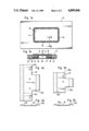
- FIG. 1a is aside view of a first example of a preferred embodiment of the present invention, showing a wall partition and a decompression panel in accordance with the invention;
- FIG. 1b is a section, as indicated by line 1b--1b in FIG. 1a, but being on an enlarged scale;
- FIGS. 2a and 2b are respectively front and side views of a spring improved in accordance with the present invention.
- FIG. 3a is another example for a wall partition showing a decompression panel when inserted, but has a modified construction, still being an example of the preferred embodiment of the invention
- FIG. 3b is a section, as indicated by 3b--3b in FIG. 3b, also being drawn to an enlarged scale, quite comparable in that regard with FIG. 1b;
- FIGS. 4a and 4b are, respectively, front and side views of a modified holding spring
- FIGS. 5a and 5b illustrate two different cases and situations of decompression in an aircraft.
- FIGS. 1a and 1b show a wall partition 13 with a decompression opening 12.
- a decompression panel 10 in accordance with the present invention, is inserted into that opening 12.
- the panel 10 is particularly constructed as a sandwich plate and includes a frame 11 holding the sandwiched lamina.
- the frame 11 has an outer contour matching that of the decompression opening 12.
- the frame 11, moreover, is provided with a U-shaped cross-section (see FIG. 1b).
- the legs of the U abut the decompression opening 12 as well as the decompression panel 10 itself.
- the decompression opening 12 as well as the panel 10 are respectively provided with grooves 14 and 15 delineating, so to speak, the opening and the panel rim, and being, respectively, provided for receiving sealing rings 16 and 17.
- These sealing rings 16 and 17 are held in position by a flat flange 18, which is fastened to the frame 11 and here particularly the front part of the U legs, e.g. by means of welding.
- a known connecting method such as resistance welding or the like provides a connection of the flange with the frame 11.
- the flange 18 has a certain width which is matched to the grooves 14 and 15 of the wall 13 and the panel 10, respectively, and to the width of frame 11.
- the length of the legs of the U-shaped cross-section of frame 11 corresponds to the thickness of the wall 13, as well as of the decompression panel 10.
- a plurality of uniformly distributed flat holding springs 19 are provided. These holding springs are illustrated by way of example in FIGS. 2a and 2b. As can be seen from these figures, the springs are constructed as flat spring elements 19 in an overall T-shaped configuration of the elevation. The stem end, as well as the upper part of the cross bar, are of trough shape. The springs 19 have openings 20 for fastening to frame 11, so that their backs abut wall 13 and the decompression panel 10, for clamping. Specifically, the trough of the cross bar of the T abuts panel 10, and the trough of the stem abuts partition 13.
- blind rivets 20 Following insertion of the frame 11 into the opening 12, and following the fastening of the decompression panel 10 to the frame 11, including placement of the seals 16 and 17, the holding springs 19 are then fastened to the frame 11 by means of blind rivets 20.
- blind rivets should be of the kind which have a universal head for general usage with a self-locking rivet structure. This way of fastening is simple, economical, and very reliable.
- the springs 19 are provided with weak lines or fracture points 19a, 19b, particularly adjacent at the clamping troughs. These fracture points will cause the springs to break in case an explosive decompression occurs on one side of the wall or the other. Since decompression is effective bi-directionally (see arrows 21 and 22), the springs have to be provided each with two rupture points or lines (19a and 19b).
- FIG. 1 is just one possible way to provide a sealing in accordance with the invention.
- FIG. 3 Another solution is shown in FIG. 3.
- the legs of a U-shaped frame are somewhat longer, namely by a value that is equivalent to the thickness of the sealing elements which are not placed in any recesses or grooves.
- these legs are angled in the edge zone of the flange 18 in order to better provide for a sealing effect.
- the springs for this example are of the type shown with a 49 in FIG. 4a and 4b. They are basically similar to the ones identified by reference numeral 19 in FIGS. 2a and 2b, but they are wider as compared with the earlier situation. Here, then, one needs not three but four blind rivets for fastening. Otherwise, of course, the situation is the same as described in FIG. 1 with, however, a somewhat differently defined differential area owing to the wider bars of the springs 19.
- flange 18 can be formed through bending the leg of a U-shaped cross-section corresponding to the frame 11.
Landscapes
- Engineering & Computer Science (AREA)
- Mechanical Engineering (AREA)
- Aviation & Aerospace Engineering (AREA)
- Connection Of Plates (AREA)
- Buildings Adapted To Withstand Abnormal External Influences (AREA)
Abstract
Description
Claims (5)
Applications Claiming Priority (2)
| Application Number | Priority Date | Filing Date | Title |
|---|---|---|---|
| DE3715328 | 1987-05-08 | ||
| DE3715328A DE3715328C1 (en) | 1987-05-08 | 1987-05-08 | Decompression panel |
Publications (1)
| Publication Number | Publication Date |
|---|---|
| US4899960A true US4899960A (en) | 1990-02-13 |
Family
ID=6327087
Family Applications (1)
| Application Number | Title | Priority Date | Filing Date |
|---|---|---|---|
| US07/191,412 Expired - Fee Related US4899960A (en) | 1987-05-08 | 1988-05-09 | Decompression panel for aircraft partition |
Country Status (3)
| Country | Link |
|---|---|
| US (1) | US4899960A (en) |
| EP (1) | EP0291661B1 (en) |
| DE (1) | DE3715328C1 (en) |
Cited By (44)
| Publication number | Priority date | Publication date | Assignee | Title |
|---|---|---|---|---|
| US5085017A (en) * | 1990-01-27 | 1992-02-04 | Deutsche Airbus Gmbh | Decompression panel for a separation device in an aircraft |
| US5116089A (en) * | 1991-05-06 | 1992-05-26 | Taylor Julian S | Explosion vent door release |
| US5137231A (en) * | 1991-04-29 | 1992-08-11 | The Boeing Company | Decompression venting grille for aircraft |
| US5236154A (en) * | 1991-07-30 | 1993-08-17 | Otten Kevin T | Cover for air intake opening at leading edge of aircraft wing |
| US5871178A (en) * | 1996-09-27 | 1999-02-16 | Mcdonnell Douglas Corporation | Decompression panel for aircraft partition |
| US6029933A (en) * | 1997-08-01 | 2000-02-29 | The Boeing Company | Fire resistant pressure relief panel assembly |
| US6129312A (en) * | 1997-09-26 | 2000-10-10 | The Boeing Company | Aircraft decompression vent assembly |
| US6264141B1 (en) | 1997-02-19 | 2001-07-24 | Mcdonnell Douglas Corporation | Aircraft decompression protection panel |
| US6659401B1 (en) * | 2002-11-13 | 2003-12-09 | Robert M. Semprini | Airplane door lock system |
| US6698690B2 (en) * | 2002-02-28 | 2004-03-02 | Alcoa Inc. | Impact resistant door containing resealable panels |
| US6702230B2 (en) | 2002-06-04 | 2004-03-09 | The Boeing Company | Ballistic resistant flight deck door assembly having ventilation feature |
| US20060065782A1 (en) * | 2004-08-03 | 2006-03-30 | Airbus | Reinforced door |
| US20060169839A1 (en) * | 2004-08-03 | 2006-08-03 | Airbus | Internal security door for an aircraft |
| US20060214284A1 (en) * | 2005-03-24 | 2006-09-28 | Stuart Haden | Apparatus and method for data capture |
| US20070089746A1 (en) * | 2005-10-06 | 2007-04-26 | The Boeing Company | Method and apparatus for extending flight crew's time of useful consciousness after decompression |
| WO2008090084A2 (en) * | 2007-01-23 | 2008-07-31 | Airbus Operations Gmbh | Lining for an aircraft |
| US20080290217A1 (en) * | 2007-05-25 | 2008-11-27 | The Boeing Company | Vent Baffle |
| US20090050741A1 (en) * | 2006-05-02 | 2009-02-26 | Airbus Deutschland Gmbh | Fire barrier for an aircraft fuselage |
| US20090159748A1 (en) * | 2007-12-20 | 2009-06-25 | Airbus Deutschland Gmbh | Decompression Device With Adjustable Release Pressure |
| US20110139931A1 (en) * | 2009-12-14 | 2011-06-16 | Be Intellectual Property, Inc. | Fireproof bidirectional decompression panel |
| US20110297787A1 (en) * | 2010-06-04 | 2011-12-08 | Airbus (S.A.S.) | Dual function door for an aircraft engine nacelle |
| CN101014498B (en) * | 2004-08-03 | 2012-01-11 | 空中客车公司 | Safety inside door for an aircraft |
| US20120214393A1 (en) * | 2011-02-22 | 2012-08-23 | Airbus Operations Gmbh | Decompression arrangement for an aircraft |
| DE102011107984A1 (en) * | 2011-07-18 | 2013-01-24 | Roland Wolf | Pressure relief device for e.g. steel concrete silo, to store bulk materials, has lateral pressure relief apertures covered with device, and pressure relief flap captively held by linked flap holder, which is fastened at container wall |
| US20130225064A1 (en) * | 2012-02-29 | 2013-08-29 | Fike Corporation | Explosion vent including buckle tab plate |
| US8651924B1 (en) * | 2010-05-06 | 2014-02-18 | The Boeing Company | Interlocking vent assembly for equalizing pressure in a compartment |
| US8714483B2 (en) | 2010-09-13 | 2014-05-06 | Airbus Operations Gmbh | Decompression device and decompression system |
| US9205908B2 (en) | 2011-03-31 | 2015-12-08 | Airbus Operations Gmbh | Locking mechanism for use in a decompression arrangement |
| US9233747B2 (en) | 2013-10-25 | 2016-01-12 | The Boeing Company | Decompression panel for use in an aircraft assembly |
| US20160148742A1 (en) * | 2013-07-16 | 2016-05-26 | Maschinenfabrik Reinhausen Gmbh | Burst protector for high-voltage device |
| US9440744B2 (en) | 2013-10-17 | 2016-09-13 | The Boeing Company | Decompression panel assembly and method of equalizing air pressure differential |
| EP3070219A1 (en) * | 2015-03-20 | 2016-09-21 | ABB Technology Oy | Explosion vent |
| US9499251B2 (en) | 2013-10-25 | 2016-11-22 | The Boeing Company | Decompression panel for use in an aircraft |
| US9566759B2 (en) | 2013-10-25 | 2017-02-14 | The Boeing Company | Decompression panel for use in an aircraft assembly |
| CN106573682A (en) * | 2014-08-20 | 2017-04-19 | 庞巴迪公司 | Actuated outlet door for aircraft high-temperature exhaust |
| USD817851S1 (en) | 2014-03-28 | 2018-05-15 | The Boeing Company | Decompression panel |
| US10071795B2 (en) | 2013-10-25 | 2018-09-11 | The Boeing Company | Clamp device for use with a decompression panel in an aircraft assembly |
| GB2567444A (en) * | 2017-10-11 | 2019-04-17 | Amsafe Bridport Ltd | Compartmental barrier with burst-out discs |
| USD908054S1 (en) * | 2018-12-19 | 2021-01-19 | The Boeing Company | Decompression panel assembly |
| US11028782B2 (en) * | 2017-10-12 | 2021-06-08 | Rolls-Royce Plc | Pressure relief arrangement for a gas turbine engine |
| US11130579B2 (en) * | 2017-05-15 | 2021-09-28 | Lufthansa Technik Ag | Device for equalizing a pressure difference for an aircraft |
| US11130558B2 (en) | 2017-05-19 | 2021-09-28 | Amsafe Bridport Limited | Compartmental barrier with decompression panels |
| WO2023137080A1 (en) * | 2022-01-11 | 2023-07-20 | Mission Critical Composites, Llc | Processes for creating local and controlled frangible areas in composites |
| US20230406522A1 (en) * | 2022-06-16 | 2023-12-21 | Airbus Operations Sas | Aircraft equipped with at least one pressure-relief device including a mobile wall retained in a closed position |
Families Citing this family (12)
| Publication number | Priority date | Publication date | Assignee | Title |
|---|---|---|---|---|
| DE3922025C1 (en) * | 1989-07-05 | 1990-08-09 | Messerschmitt-Boelkow-Blohm Gmbh, 8012 Ottobrunn, De | |
| US5118053A (en) * | 1989-09-27 | 1992-06-02 | The Boeing Company | Pressure equalization systems |
| US5069401A (en) * | 1989-11-15 | 1991-12-03 | The Boeing Company | Compartment partition and pressure relief door therefor |
| DE4103013A1 (en) * | 1991-02-01 | 1992-08-06 | Airbus Gmbh | Decompression panel for floor of passenger aircraft - is held in place by friction of retaining elements |
| DE4103014C1 (en) * | 1991-02-01 | 1992-03-12 | Deutsche Airbus Gmbh, 2000 Hamburg, De | Retaining lock for pressurised aircraft - has slidable lock sections held by axial locking pins and shear pins |
| DE4216277C2 (en) * | 1992-05-16 | 1994-12-01 | Deutsche Aerospace Airbus | Decompression panel for partitions and floors of passenger and cargo compartments in aircraft |
| DE19735917B4 (en) * | 1997-08-19 | 2008-12-04 | Volkswagen Ag | Self-supporting interior trim panel for a vehicle and method of manufacture |
| DE102004009017B3 (en) * | 2004-02-25 | 2005-08-04 | Aircabin Gmbh | Decompression device for two sDEarate regions of aircraft has locking device with release element in control cavity |
| DE102007027550A1 (en) | 2007-06-15 | 2008-12-18 | Airbus Deutschland Gmbh | Differential pressure controlled locking mechanism |
| DE202009018690U1 (en) | 2009-08-24 | 2012-09-14 | Airbus Operations Gmbh | Decompression element mounting system for an aircraft |
| AT510153B1 (en) * | 2010-10-19 | 2012-02-15 | Facc Ag | decompression |
| DE102014007975B4 (en) | 2014-06-04 | 2016-06-02 | Airbus Operations Gmbh | Support core composite plate as well as decompression system |
Citations (10)
| Publication number | Priority date | Publication date | Assignee | Title |
|---|---|---|---|---|
| US2209399A (en) * | 1937-12-31 | 1940-07-30 | Standard Oil Dev Co | Tank roof |
| GB558140A (en) * | 1942-07-10 | 1943-12-22 | Phillips & Powis Aircraft Ltd | Improvements in detachable panel mountings |
| US2355485A (en) * | 1942-06-04 | 1944-08-08 | Tinnerman Products Inc | Fastening device |
| US3571977A (en) * | 1969-06-27 | 1971-03-23 | Boeing Co | Access and pressure release door latch mechanism |
| US3864881A (en) * | 1973-07-12 | 1975-02-11 | Clarence P Wolf | Blowout panel system for building walls |
| US3972442A (en) * | 1974-11-14 | 1976-08-03 | Simon-Carves Limited | Safety equipment |
| US4027436A (en) * | 1976-03-15 | 1977-06-07 | Walcon Corporation | Explosion venting wall structure with releasable fastener means |
| US4553559A (en) * | 1983-04-29 | 1985-11-19 | Bs&B Safety Systems, Inc. | Rupturable pressure relief assembly |
| US4656793A (en) * | 1981-04-13 | 1987-04-14 | Jansens & Dieperink B.V. | Explosion cover plate especially explosion hatch |
| US4703908A (en) * | 1975-04-11 | 1987-11-03 | Gilbert Correge et a. | Safety device against a sudden decompression in the luggage compartment of an aircraft |
Family Cites Families (5)
| Publication number | Priority date | Publication date | Assignee | Title |
|---|---|---|---|---|
| US2613402A (en) * | 1949-10-13 | 1952-10-14 | Saunders Roe Ltd | Window for pressurized chambers |
| US4049221A (en) * | 1975-12-24 | 1977-09-20 | Lockheed Aircraft Corporation | Relief of inter-compartment differential pressure in aircraft |
| US4390152A (en) * | 1976-05-13 | 1983-06-28 | Lockheed Corporation | Aircraft decompression vent assembly |
| DE2756726C2 (en) * | 1977-12-20 | 1982-04-08 | Messerschmitt-Bölkow-Blohm GmbH, 8000 München | Device for pressure equalization in an aircraft or spacecraft |
| DE3011109C2 (en) * | 1980-03-22 | 1983-01-05 | Vereinigte Flugtechnische Werke Gmbh, 2800 Bremen | Safety device for aircraft |
-
1987
- 1987-05-08 DE DE3715328A patent/DE3715328C1/en not_active Expired
-
1988
- 1988-03-24 EP EP88104704A patent/EP0291661B1/en not_active Expired - Lifetime
- 1988-05-09 US US07/191,412 patent/US4899960A/en not_active Expired - Fee Related
Patent Citations (10)
| Publication number | Priority date | Publication date | Assignee | Title |
|---|---|---|---|---|
| US2209399A (en) * | 1937-12-31 | 1940-07-30 | Standard Oil Dev Co | Tank roof |
| US2355485A (en) * | 1942-06-04 | 1944-08-08 | Tinnerman Products Inc | Fastening device |
| GB558140A (en) * | 1942-07-10 | 1943-12-22 | Phillips & Powis Aircraft Ltd | Improvements in detachable panel mountings |
| US3571977A (en) * | 1969-06-27 | 1971-03-23 | Boeing Co | Access and pressure release door latch mechanism |
| US3864881A (en) * | 1973-07-12 | 1975-02-11 | Clarence P Wolf | Blowout panel system for building walls |
| US3972442A (en) * | 1974-11-14 | 1976-08-03 | Simon-Carves Limited | Safety equipment |
| US4703908A (en) * | 1975-04-11 | 1987-11-03 | Gilbert Correge et a. | Safety device against a sudden decompression in the luggage compartment of an aircraft |
| US4027436A (en) * | 1976-03-15 | 1977-06-07 | Walcon Corporation | Explosion venting wall structure with releasable fastener means |
| US4656793A (en) * | 1981-04-13 | 1987-04-14 | Jansens & Dieperink B.V. | Explosion cover plate especially explosion hatch |
| US4553559A (en) * | 1983-04-29 | 1985-11-19 | Bs&B Safety Systems, Inc. | Rupturable pressure relief assembly |
Cited By (75)
| Publication number | Priority date | Publication date | Assignee | Title |
|---|---|---|---|---|
| US5085017A (en) * | 1990-01-27 | 1992-02-04 | Deutsche Airbus Gmbh | Decompression panel for a separation device in an aircraft |
| US5137231A (en) * | 1991-04-29 | 1992-08-11 | The Boeing Company | Decompression venting grille for aircraft |
| US5116089A (en) * | 1991-05-06 | 1992-05-26 | Taylor Julian S | Explosion vent door release |
| US5236154A (en) * | 1991-07-30 | 1993-08-17 | Otten Kevin T | Cover for air intake opening at leading edge of aircraft wing |
| US5871178A (en) * | 1996-09-27 | 1999-02-16 | Mcdonnell Douglas Corporation | Decompression panel for aircraft partition |
| US6264141B1 (en) | 1997-02-19 | 2001-07-24 | Mcdonnell Douglas Corporation | Aircraft decompression protection panel |
| US6029933A (en) * | 1997-08-01 | 2000-02-29 | The Boeing Company | Fire resistant pressure relief panel assembly |
| EP0894709A3 (en) * | 1997-08-01 | 2001-02-07 | The Boeing Company | Fire resistant pressure relief panel assembly |
| CN1087701C (en) * | 1997-08-01 | 2002-07-17 | 波音公司 | Fire resistant pressure relief panel assembly |
| US6129312A (en) * | 1997-09-26 | 2000-10-10 | The Boeing Company | Aircraft decompression vent assembly |
| US6698690B2 (en) * | 2002-02-28 | 2004-03-02 | Alcoa Inc. | Impact resistant door containing resealable panels |
| US6702230B2 (en) | 2002-06-04 | 2004-03-09 | The Boeing Company | Ballistic resistant flight deck door assembly having ventilation feature |
| US6659401B1 (en) * | 2002-11-13 | 2003-12-09 | Robert M. Semprini | Airplane door lock system |
| US20040089766A1 (en) * | 2002-11-13 | 2004-05-13 | Semprini Robert M. | Airplane door lock system |
| US6817577B2 (en) | 2002-11-13 | 2004-11-16 | Robert M. Semprini | Airplane door lock system |
| US20060065782A1 (en) * | 2004-08-03 | 2006-03-30 | Airbus | Reinforced door |
| US20060169839A1 (en) * | 2004-08-03 | 2006-08-03 | Airbus | Internal security door for an aircraft |
| US7578477B2 (en) * | 2004-08-03 | 2009-08-25 | Airbus | Internal security door for an aircraft |
| CN101014498B (en) * | 2004-08-03 | 2012-01-11 | 空中客车公司 | Safety inside door for an aircraft |
| US7600716B2 (en) | 2004-08-03 | 2009-10-13 | Airbus | Reinforced door |
| US20060214284A1 (en) * | 2005-03-24 | 2006-09-28 | Stuart Haden | Apparatus and method for data capture |
| US20070089746A1 (en) * | 2005-10-06 | 2007-04-26 | The Boeing Company | Method and apparatus for extending flight crew's time of useful consciousness after decompression |
| US7624732B2 (en) * | 2005-10-06 | 2009-12-01 | The Boeing Company | Method and apparatus for extending flight crew's time of useful consciousness after decompression |
| US20090050741A1 (en) * | 2006-05-02 | 2009-02-26 | Airbus Deutschland Gmbh | Fire barrier for an aircraft fuselage |
| US7997533B2 (en) * | 2006-05-02 | 2011-08-16 | Airbus Deutschland Gmbh | Fire barrier for an aircraft fuselage |
| US20100096500A1 (en) * | 2007-01-23 | 2010-04-22 | Hermann Benthien | Lining for an aircraft |
| WO2008090084A2 (en) * | 2007-01-23 | 2008-07-31 | Airbus Operations Gmbh | Lining for an aircraft |
| JP2010516550A (en) * | 2007-01-23 | 2010-05-20 | エアバス・オペレーションズ・ゲーエムベーハー | Aircraft lining |
| US8490922B2 (en) | 2007-01-23 | 2013-07-23 | Airbus Operations Gmbh | Lining for an aircraft |
| CN101636315B (en) * | 2007-01-23 | 2013-04-17 | 空中客车运营有限公司 | Lining for an aircraft |
| WO2008090084A3 (en) * | 2007-01-23 | 2008-09-18 | Airbus Gmbh | Lining for an aircraft |
| RU2463206C2 (en) * | 2007-01-23 | 2012-10-10 | Эйрбас Оперейшенз Гмбх | Cladding for aircraft |
| US7654487B2 (en) * | 2007-05-25 | 2010-02-02 | The Boeing Company | Vent baffle |
| US20080290217A1 (en) * | 2007-05-25 | 2008-11-27 | The Boeing Company | Vent Baffle |
| US20090159748A1 (en) * | 2007-12-20 | 2009-06-25 | Airbus Deutschland Gmbh | Decompression Device With Adjustable Release Pressure |
| US8201775B2 (en) * | 2007-12-20 | 2012-06-19 | Airbus Deutschland Gmbh | Improved decompression device with adjustable release pressure |
| US8240604B2 (en) * | 2009-12-14 | 2012-08-14 | Be Intellectual Property, Inc. | Fireproof bidirectional decompression panel |
| WO2011081830A2 (en) | 2009-12-14 | 2011-07-07 | Be Intellectual Property, Inc. | Fireproof bidirectional decompression panel |
| JP2013518752A (en) * | 2009-12-14 | 2013-05-23 | ビーイー・インテレクチュアル・プロパティー・インコーポレイテッド | Fireproof bidirectional decompression panel |
| US20110139931A1 (en) * | 2009-12-14 | 2011-06-16 | Be Intellectual Property, Inc. | Fireproof bidirectional decompression panel |
| AU2010337185B2 (en) * | 2009-12-14 | 2016-09-08 | Be Intellectual Property, Inc. | Fireproof bidirectional decompression panel |
| US8651924B1 (en) * | 2010-05-06 | 2014-02-18 | The Boeing Company | Interlocking vent assembly for equalizing pressure in a compartment |
| US20110297787A1 (en) * | 2010-06-04 | 2011-12-08 | Airbus (S.A.S.) | Dual function door for an aircraft engine nacelle |
| US8657234B2 (en) * | 2010-06-04 | 2014-02-25 | Airbus Operations S.A.S. | Dual function door for an aircraft engine nacelle |
| US8714483B2 (en) | 2010-09-13 | 2014-05-06 | Airbus Operations Gmbh | Decompression device and decompression system |
| US9022321B2 (en) * | 2011-02-22 | 2015-05-05 | Airbus Operations Gmbh | Decompression arrangement for an aircraft including a bi-directional flap |
| US20120214393A1 (en) * | 2011-02-22 | 2012-08-23 | Airbus Operations Gmbh | Decompression arrangement for an aircraft |
| US9205908B2 (en) | 2011-03-31 | 2015-12-08 | Airbus Operations Gmbh | Locking mechanism for use in a decompression arrangement |
| DE102011107984A1 (en) * | 2011-07-18 | 2013-01-24 | Roland Wolf | Pressure relief device for e.g. steel concrete silo, to store bulk materials, has lateral pressure relief apertures covered with device, and pressure relief flap captively held by linked flap holder, which is fastened at container wall |
| US9199789B2 (en) * | 2012-02-29 | 2015-12-01 | Fike Corporation | Explosion vent including buckle tab plate |
| US20130225064A1 (en) * | 2012-02-29 | 2013-08-29 | Fike Corporation | Explosion vent including buckle tab plate |
| US9899134B2 (en) * | 2013-07-16 | 2018-02-20 | Maschinenfabrik Reinhausen Gmbh | Burst protector for high-voltage device |
| US20160148742A1 (en) * | 2013-07-16 | 2016-05-26 | Maschinenfabrik Reinhausen Gmbh | Burst protector for high-voltage device |
| US9440744B2 (en) | 2013-10-17 | 2016-09-13 | The Boeing Company | Decompression panel assembly and method of equalizing air pressure differential |
| US9566759B2 (en) | 2013-10-25 | 2017-02-14 | The Boeing Company | Decompression panel for use in an aircraft assembly |
| US9499251B2 (en) | 2013-10-25 | 2016-11-22 | The Boeing Company | Decompression panel for use in an aircraft |
| US9233747B2 (en) | 2013-10-25 | 2016-01-12 | The Boeing Company | Decompression panel for use in an aircraft assembly |
| US9751609B2 (en) | 2013-10-25 | 2017-09-05 | The Boeing Company | Decompression panel for use in an aircraft |
| US10071795B2 (en) | 2013-10-25 | 2018-09-11 | The Boeing Company | Clamp device for use with a decompression panel in an aircraft assembly |
| USD817851S1 (en) | 2014-03-28 | 2018-05-15 | The Boeing Company | Decompression panel |
| CN106573682B (en) * | 2014-08-20 | 2020-03-27 | 庞巴迪公司 | Actuated exit door for high temperature exhaust of aircraft |
| CN106573682A (en) * | 2014-08-20 | 2017-04-19 | 庞巴迪公司 | Actuated outlet door for aircraft high-temperature exhaust |
| US10549863B2 (en) | 2014-08-20 | 2020-02-04 | Bombardier Inc. | Actuated outlet door for aircraft high-temperature exhaust |
| CN105987209A (en) * | 2015-03-20 | 2016-10-05 | Abb技术有限公司 | Explosion vent |
| CN105987209B (en) * | 2015-03-20 | 2019-09-13 | Abb瑞士股份有限公司 | Vented explosion mouth |
| US9903491B2 (en) | 2015-03-20 | 2018-02-27 | Abb Technology Oy | Explosion vent |
| EP3070219A1 (en) * | 2015-03-20 | 2016-09-21 | ABB Technology Oy | Explosion vent |
| US11130579B2 (en) * | 2017-05-15 | 2021-09-28 | Lufthansa Technik Ag | Device for equalizing a pressure difference for an aircraft |
| US11130558B2 (en) | 2017-05-19 | 2021-09-28 | Amsafe Bridport Limited | Compartmental barrier with decompression panels |
| GB2567444A (en) * | 2017-10-11 | 2019-04-17 | Amsafe Bridport Ltd | Compartmental barrier with burst-out discs |
| GB2567444B (en) * | 2017-10-11 | 2021-07-14 | Amsafe Bridport Ltd | Compartmental barrier with burst-out discs |
| US11028782B2 (en) * | 2017-10-12 | 2021-06-08 | Rolls-Royce Plc | Pressure relief arrangement for a gas turbine engine |
| USD908054S1 (en) * | 2018-12-19 | 2021-01-19 | The Boeing Company | Decompression panel assembly |
| WO2023137080A1 (en) * | 2022-01-11 | 2023-07-20 | Mission Critical Composites, Llc | Processes for creating local and controlled frangible areas in composites |
| US20230406522A1 (en) * | 2022-06-16 | 2023-12-21 | Airbus Operations Sas | Aircraft equipped with at least one pressure-relief device including a mobile wall retained in a closed position |
Also Published As
| Publication number | Publication date |
|---|---|
| EP0291661A3 (en) | 1989-11-29 |
| EP0291661B1 (en) | 1992-05-06 |
| DE3715328C1 (en) | 1988-08-18 |
| EP0291661A2 (en) | 1988-11-23 |
Similar Documents
| Publication | Publication Date | Title |
|---|---|---|
| US4899960A (en) | Decompression panel for aircraft partition | |
| US5871178A (en) | Decompression panel for aircraft partition | |
| US6443392B2 (en) | Monolithic structure with redundant load paths | |
| US5085017A (en) | Decompression panel for a separation device in an aircraft | |
| US8826597B2 (en) | Weatherproof surround for safely jettisoning a removable panel | |
| US8684308B2 (en) | Universal arrangement for receiving a curtain rail for a partitioning curtain | |
| US4728059A (en) | Pressurized wall in aircraft | |
| CA2784011C (en) | Fireproof bidirectional decompression panel | |
| US20200317322A1 (en) | Emergency exit assembly for an aircraft | |
| US5934742A (en) | Plate trailer with logistics slots | |
| EP2660142B1 (en) | Method and apparatus for establishing an environmentally isolated volume | |
| US6676079B2 (en) | Passenger aircraft | |
| US20180297707A1 (en) | Separable vehicle cabin privacy partition assemblies which allow for emergency egress | |
| US4049221A (en) | Relief of inter-compartment differential pressure in aircraft | |
| EP0432809A1 (en) | Pressure relief door | |
| US10906648B2 (en) | Arrangement in a vehicle cabin with cabin monuments placeable in rows with laminar contact of the lateral surfaces thereof | |
| RU2719096C2 (en) | Method, system and lining of cargo compartment of aircraft | |
| US2736521A (en) | Flexible tank wall edge seals | |
| EP3919383A1 (en) | Inflatable isolation walls for aircraft cabins | |
| US10640192B2 (en) | Aircraft having a removable hold | |
| EP3403921B1 (en) | Compartmental barrier with decompression panels | |
| US20040000094A1 (en) | Rapid-opening door | |
| US10086947B2 (en) | System and method of suppressing an unexpected combustion event | |
| JPS62194998A (en) | Empennage-breakdown preventive device | |
| WO2019041030A1 (en) | Latch assembly for aircraft monument |
Legal Events
| Date | Code | Title | Description |
|---|---|---|---|
| AS | Assignment |
Owner name: MESSSERSCHMITT-BOELKOW-BLOHM GMBH, 8012 OTTOBRUNN, Free format text: ASSIGNMENT OF ASSIGNORS INTEREST.;ASSIGNORS:SCHWARZ, FRANK;MOHAMED, HARARAT-TEHRANI;HARARAT-TEHRANI, MOHAMAD;REEL/FRAME:004906/0398;SIGNING DATES FROM |
|
| FEPP | Fee payment procedure |
Free format text: PAYOR NUMBER ASSIGNED (ORIGINAL EVENT CODE: ASPN); ENTITY STATUS OF PATENT OWNER: LARGE ENTITY |
|
| REMI | Maintenance fee reminder mailed | ||
| FPAY | Fee payment |
Year of fee payment: 4 |
|
| SULP | Surcharge for late payment | ||
| FPAY | Fee payment |
Year of fee payment: 8 |
|
| REMI | Maintenance fee reminder mailed | ||
| LAPS | Lapse for failure to pay maintenance fees | ||
| STCH | Information on status: patent discontinuation |
Free format text: PATENT EXPIRED DUE TO NONPAYMENT OF MAINTENANCE FEES UNDER 37 CFR 1.362 |
|
| FP | Lapsed due to failure to pay maintenance fee |
Effective date: 20020213 |