US4899843A - Center member structure for motor vehicle - Google Patents
Center member structure for motor vehicle Download PDFInfo
- Publication number
- US4899843A US4899843A US07/199,345 US19934588A US4899843A US 4899843 A US4899843 A US 4899843A US 19934588 A US19934588 A US 19934588A US 4899843 A US4899843 A US 4899843A
- Authority
- US
- United States
- Prior art keywords
- pipe members
- portions
- center member
- pipe
- member structure
- Prior art date
- Legal status (The legal status is an assumption and is not a legal conclusion. Google has not performed a legal analysis and makes no representation as to the accuracy of the status listed.)
- Expired - Lifetime
Links
Images


Classifications
-
- B—PERFORMING OPERATIONS; TRANSPORTING
- B62—LAND VEHICLES FOR TRAVELLING OTHERWISE THAN ON RAILS
- B62D—MOTOR VEHICLES; TRAILERS
- B62D21/00—Understructures, i.e. chassis frame on which a vehicle body may be mounted
-
- B—PERFORMING OPERATIONS; TRANSPORTING
- B62—LAND VEHICLES FOR TRAVELLING OTHERWISE THAN ON RAILS
- B62D—MOTOR VEHICLES; TRAILERS
- B62D21/00—Understructures, i.e. chassis frame on which a vehicle body may be mounted
- B62D21/11—Understructures, i.e. chassis frame on which a vehicle body may be mounted with resilient means for suspension, e.g. of wheels or engine; sub-frames for mounting engine or suspensions
-
- B—PERFORMING OPERATIONS; TRANSPORTING
- B60—VEHICLES IN GENERAL
- B60K—ARRANGEMENT OR MOUNTING OF PROPULSION UNITS OR OF TRANSMISSIONS IN VEHICLES; ARRANGEMENT OR MOUNTING OF PLURAL DIVERSE PRIME-MOVERS IN VEHICLES; AUXILIARY DRIVES FOR VEHICLES; INSTRUMENTATION OR DASHBOARDS FOR VEHICLES; ARRANGEMENTS IN CONNECTION WITH COOLING, AIR INTAKE, GAS EXHAUST OR FUEL SUPPLY OF PROPULSION UNITS IN VEHICLES
- B60K5/00—Arrangement or mounting of internal-combustion or jet-propulsion units
- B60K5/12—Arrangement of engine supports
Definitions
- the present invention relates in general to a support structure installed in a motor vehicle, and more particularly to a center member structure designed to carry thereon an engine unit of the motor vehicle.
- a center member structure is commonly employed which is designed to carry the engine unit thereon.
- the center member structure extends along the longitudinal axis of the vehicle and has both ends secured to axially spaced portions of a body of the vehicle respectively.
- very high strength is required by the center member structure.
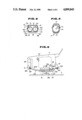
- FIGS. 17 and 18 of the accompanying drawings One of the conventional center member structures is shown in FIGS. 17 and 18 of the accompanying drawings.
- the structure comprises a longitudinally curved channel member 2 and a longitudinally curved plate member 4 which are spot-welded to constitute a longitudinally curved hollow structure.
- a reinforcing member 6 is attached to the inner surface of the channel member 2 to increase the mechanical strength of the structure.
- Numerals 5 denote the portions to which the spot welding is practically applied.
- a center member structure which comprises two pipe members which are arranged side by side and joined together.
- a center member structure for use in a motor vehicle to support thereon an engine unit, the structure comprising two pipe members arranged side by side and having first portions which extend in parallel and second portions which gradually separate from each other with increase of distance from the generally middle portions of the pipe members, and reinforcing plates welded to given portions of the two pipe members to securely combine the pipe members into a robust unit.
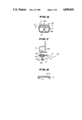
- FIG. 1 is a perspective view of a center member structure of a first embodiment of the present invention
- FIG. 2 is a plan view of the structure of the first embodiment with an upper reinforcing cover plate removed;
- FIG. 3 is a sectional view taken along the line III--III of FIG. 1;
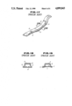
- FIG. 4 is a sectional view similar to FIG. 3, but showing a case wherein only one pipe member is employed for a center member structure, which view is provided for stressing an advantageous feature of the first embodiment;
- FIG. 5 is an illustration of a front portion of a motor vehicle, to which the center member structure of the invention is mounted in practice;
- FIG. 6 is a sectional, but enlarged, view taken along the line VI--VI of FIG. 5;
- FIG. 7 is a sectional view of a front part of the center member structure illustrating how it is fixed to a motor vehicle body by a bolt;
- FIG. 8 is a sectional view of an end portion of a modified center member structure
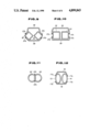
- FIGS. 9, 10, 11 and 12 are sectional views similar to FIG. 3, but showing second, third, fourth and fifth embodiments of the present invention.
- FIG. 13 is a plan view similar to FIG. 2, but showing a sixth embodiment of the present invention.
- FIG. 14 is a sectional view taken along the line XIV--XIV of FIG. 13;
- FIG. 15 is a plan view similar to FIG. 2, but showing a seventh embodiment of the present invention.
- FIG. 16 is a sectional view taken along the line XVI--XVI of FIG. 15;
- FIG. 17 is a perspective view of a conventional center member structure
- FIG. 18 is a sectional view taken along the line XVIII--XVIII of FIG. 17;
- FIG. 19 is a view similar to FIG. 18, but showing a condition wherein the structure is deformed.
- the center member structure 10 comprises generally a center member proper 10A which is constructed of two identical steel pipes 12 and 14, and upper and lower reinforcing cover plates 16 and 18 which are secured to the pipes 12 and 14 to join the same together.
- Each pipe 12 or 14 is longitudinally curved, bow-like and has a circular cross section as shown in FIG. 3. As is seen from FIG. 1, the two pipes 12 and 14 are arranged side by side and they have right parts, as viewed in the drawing, extending in parallel and left parts gradually separating from each other with increase of distance from the middle portions thereof.
- the upper reinforcing cover plate 16 is longer than the lower one 18.
- Each cover plate 16 or 18 has inclined side walls 16a or 18a (see FIG. 3). These cover plates 16 and 18 are arranged above and below the pipes 14 and 16 to put therebetween the parallel extending portions of the pipes 12 and 14 and welded thereto at the edges of the side walls 16a and 18a to join the two pipes 12 and 14 tightly together.
- intermittent arc-welding is employed for the connection between each cover plate 16 or 18 and each pipe 12 or 14.
- the welded portions are denoted by numerals 17a and 17b.
- front (viz., left as viewed in the drawings) ends of the side walls 16a or 18a of each cover plate 16 or 18 is curved outwardly to accommodate the left parts of the pipes 12 and 14.
- the lower cover plate 18 is in contact with the lower surfaces of the pipes 12 and 14 so that an exposed (viz., lower) surface of the cover plate 18 serves as a so-called "jack up zone" against which a jack-up tool abuts of an associated motor vehicle when it is jacked-up.
- the upper cover plate 16 is arranged to leave a given space "d" between a major portion thereof and the upper portion of each pipe 12 or 14.
- the upper and lower cover plates 16 and 18 function not only to join the pipes 12 and 14 together but also increase the modulus of a section of the center member structure 10. Increasing the modulus of section is important to bear the great bending moment which is applied to the structure 10 upon jacking-up of the vehicle.
- the width (viz., the height) of each side wall 16a of the upper cover plate 16 has a relationship with the mechanical strength of the structure 10. That is, the strength is increased with increase of the height of each side wall 16a.
- both ends 12a and 12b (or, 14a and 14b) of each pipe 12 or 14 are pressed flat except outer side edges 12a 1 and 12b 1 (or, 14a 1 and 14b 1 ) thereof.
- each side edge defines therein a small passage 15 which is communicated with the interior of the pipe 12 or 14.
- the paint liquid is permitted to flow into the interiors of the pipes 12 and 14 through the passages 15.
- the passages 15 and 15 may be formed at both side edges of the pressed end of each pipe 12 or 14.
- the mutually spaced left ends 12a and 14a of the pipes 12 and 14 are welded to a common bracket 20, while, the right ends 12b and 14b of the same are welded directly to each other.
- Numerals 17c, 17d and 17e denote the portions to which the welding is applied.
- the parallel extending portions of the pipes 12 and 14 have near the right ends 12b and 14b curved portions 12c and 14c to which an obtusely bent bracket 22 is welded at the peripheral edges thereof.
- the upper cover plate 16 and the bracket 22 are respectively formed with bolt holes 24 and 26.
- an engine mount 38 is tightly disposed on the center member structure 10 in a manner as will be described in detail hereinafter.
- both ends 12a and 12b (or, 14a and 14b) of each pipe 12 or 14 are formed with bolt holes 12d 1 and 12d 2 (or, 14d 1 and 14d 2 ).
- the front ends 12a and 14a of the joined pipes 12 and 14 are attached to a lower surface of a front cross member 31 and secured thereto by using bolts 32a and nuts 32b, and the rear ends 12b and 14b of the same are attached to a lower surface of a dash panel 33 and secured thereby by using bolts 32a and nuts 32b.
- FIG. 7 shows in detail the manner in which the front end 12a or 14a of each pipe 12 or 14 is secured to the front cross member 31.
- the bolt hole 12d 1 or 14d 1 of the pipe end 12a or 14a is a longitudinally extending slot which is equipped with a rubber bushing 34.
- a rubber bushing 34 Within an elongate opening 34a thus defined by the rubber bushing 34, there is slidably received a cylindrical spacer 36.
- the nut 32b is welded to the front cross member 31.
- the bolt 32a is passed through the spacer 36 in the rubber bushing 34 and screwed into the nut 32b of the cross member 31.
- Denoted by numeral 37 is a washer for the bolt 32a.
- the bolt hole 12d 2 or 14d 2 of the pipe right end 12b or 14b is a circular opening.
- the right ends 12b and 14b are secured to the dash panel 33 in substantially the same manner as in the case of the front ends 12a and 14a. That is, the connection between the rear end 12b or 14b of each pipe 12 or 14 and the dash panel 33 is elastically made due to provision of a rubber bushes disposed therebetween. Thus, any vibration applied to the center member structure 10 is damped to a certain extent by the rubber bushings.
- the engine mount 38 is secured to both a rear end portion of the upper reinforcing cover plate 16 and the obtusely bent bracket 22 by means of bolts 39a and nuts 39b.
- a pair of upper engine mounts 40 (only one is shown) are secured to respective brackets (not shown) which are secured to laterally spaced portions of the vehicle body.
- the space "d" defined between the upper cover plate 16 and the two joined pipes 12 and 14 is sized to neatly accommodate the nut 39b for the bolt 39a by which the engine mount 38 is fixed to the upper cover plate 16.
- the engine mounts 38, 40 and 40 are equipped with rubber insulators, so that the engine unit "E” is resiliently supported by them.
- Designated by numerals 42 and 44 are a radiator and a front tire of the vehicle.
- Reference “G” denotes a surface of the road.
- the structure 10 is constructed of two pipes 12 and 14 joined together by the upper and lower reinforcing cover plates 16 and 18, it can bear a great load even when the diameter and thickness of the pipes are not large.
- large-sized and thus expensive press machines are not necessary. Usage of such small sized pipes facilitates design change of the structure 10.
- a larger jack up zone can be provided by the structure 10. This will be apparent when compared with a structure of FIG. 4 wherein only one but larger pipe 13 is used to provide the structure with a mechanical strength substantially equal to that of the invention. That is, if, upon jacking up of an associated vehicle, the jack up point "P 1 " is somewhat displaced from a desired center position of the jack-up zone "S 1 ", a considerable bending moment "P 2 " is produced in the pipe 13. That is, the jack-up zone "S 1 " is limited to the restricted center portion coincident with the longitudinal axis "O 13 " of the pipe 13.
- the structure 10 of the invention can provide a sufficiently large jack up zone "S 2 " which is bounded by the longitudinal axes "O 12 " and “O 14 " of the pipes 12 and 14.
- the larger jack up zone can minimize damage of the center member structure 10 which may be inflicted when the same collides against the road surface as the vehicle travels.
- the center member structure 10 is constructed of smaller diameter pipes which are easily produced.
- the center member structure 10 can be produced with a reduced thickness. This results in an increase in distance between the center member structure 10 mounted to the vehicle body and a road surface.
- the structure 10 has a simple and smoothed configulation, application of paint thereto is easily achieved.
- the structure has a quite strong construction.
- the space "d” can be used to neatly receiving the nut 39b for the bolt 39a by which the engine mount 38 is fixed to the upper cover plate 16.
- FIGS. 9 and 10 there are shown second and third embodiments of the present invention wherein two rectangular cross section pipes 52 and 54, an upper reinforcing cover plate 56 and a lower reinforcing cover plate 58 are assembled in substantially the same manner as mentioned in the description of the first embodiment 10.
- the pipes 52 and 54 are angularly raised relative to the lower cover plate 58
- the pipes 52 and 54 are stably laid on the plate 58.
- numerals 57a and 57b denote the arc welded intermittent portions.
- FIGS. 11 and 12 there are shown fourth and fifth embodiments of the present invention.
- two semicircular cross section pipes 62 and 64 are welded at their flat side portions
- two pipes 72 and 74 of oval cross section are used.
- Upper and lower reinforcing cover plates 76 and 78 are welded to the pipes 72 and 74 in the above-mentioned manner.
- numerals 67a, 67b, 77a and 77b denote the arc welded portions.
- FIGS. 13 and 14 there is shown a sixth embodiment of the present invention.
- the two pipes 12' and 14' are different in shape. That is, the pipe 12' is bent larger than the other 14', and the cylindrical wall of the pipe 12' is thicker than that of the other 14'. But, they are the same in outer diameter.
- FIGS. 15 and 16 there is shown a seventh embodiment of the present invention.
- two different pipes 12" and 14" are used for constituting a center member structure. That is, as is shown, the pipe 12" is bent more than the other pipe 14" and has a larger outer diameter than the other pipe 14". But, they are the same in thickness of the cylindrical wall.
- the center member structure of the sixth or the seventh embodiment is arranged offset with respect to the longitudinal axis of the vehicle body. That is, upon mounting, the center member structure is so arranged that the largely bent pipe 12' or 12" is located nearer the longitudinal axis than the other pipe 14' or 14". This is because upon jacking-up the associated motor vehicle, the load applied to the pipe 12' or 12" is greater than that applied to the other pipe 14' or 14".
Landscapes
- Engineering & Computer Science (AREA)
- Chemical & Material Sciences (AREA)
- Combustion & Propulsion (AREA)
- Transportation (AREA)
- Mechanical Engineering (AREA)
- Body Structure For Vehicles (AREA)
- Arrangement Or Mounting Of Propulsion Units For Vehicles (AREA)
Abstract
Description
Claims (28)
A/2≧B
Applications Claiming Priority (2)
| Application Number | Priority Date | Filing Date | Title |
|---|---|---|---|
| JP62-177085 | 1987-07-17 | ||
| JP62177085A JP2628861B2 (en) | 1987-07-17 | 1987-07-17 | Automotive center member structure |
Publications (1)
| Publication Number | Publication Date |
|---|---|
| US4899843A true US4899843A (en) | 1990-02-13 |
Family
ID=16024864
Family Applications (1)
| Application Number | Title | Priority Date | Filing Date |
|---|---|---|---|
| US07/199,345 Expired - Lifetime US4899843A (en) | 1987-07-17 | 1988-05-26 | Center member structure for motor vehicle |
Country Status (4)
| Country | Link |
|---|---|
| US (1) | US4899843A (en) |
| JP (1) | JP2628861B2 (en) |
| KR (1) | KR910003181B1 (en) |
| GB (1) | GB2207100B (en) |
Cited By (27)
| Publication number | Priority date | Publication date | Assignee | Title |
|---|---|---|---|---|
| US5092554A (en) * | 1991-04-12 | 1992-03-03 | Gibbs Myron F | Temporary transmission/engine support system |
| US5472063A (en) * | 1991-04-23 | 1995-12-05 | Mazda Motor Corporation | Front body structure of automotive vehicle |
| US5477938A (en) * | 1990-10-08 | 1995-12-26 | Mazda Motor Corporation | Power plant supporting structure of automotive vehicle |
| US5593001A (en) * | 1993-06-11 | 1997-01-14 | Yamakawa Industrial Co., Ltd. | Mount supporting member and manufacturing method therefor |
| US5884722A (en) * | 1997-01-23 | 1999-03-23 | Dana Corporation | Engine cradle for vehicle body and frame assembly and method of manufacturing same |
| US6000719A (en) * | 1997-04-28 | 1999-12-14 | The Budd Company | Body bracket and welding technique |
| US6065559A (en) * | 1998-09-22 | 2000-05-23 | Chrysler Corporation | Support structure for a vehicle powertrain |
| US6149197A (en) * | 1997-06-06 | 2000-11-21 | Suzuki Motor Corporation | Structure of front body of automobiles |
| US6382695B1 (en) * | 1998-09-21 | 2002-05-07 | Vallourec Composants Automobiles Hautmont | Hollow elongated support structure comprising a transverse flange at each of its ends |
| US6397965B1 (en) * | 2000-08-31 | 2002-06-04 | New Flyer Industries Limited | Engine configuration for mass transit vehicle |
| US6408515B1 (en) | 1998-08-20 | 2002-06-25 | Dana Corporation | Method for manufacturing an engine cradle for a vehicle frame assembly |
| US6834910B2 (en) * | 2000-05-11 | 2004-12-28 | Bayerische Motoren Werke Aktiengesellschaft | Y-rear brace for increasing the bending and torsional rigidity of a base chassis |
| US20050115758A1 (en) * | 2003-12-01 | 2005-06-02 | Honda Motor Co., Ltd. | Vehicle body frame structure |
| FR2876929A1 (en) * | 2004-10-27 | 2006-04-28 | Renault Sas | Steel body shell structural part e.g. longeron, manufacturing method for motor vehicle, involves forming rib simultaneously, at proximity to bent portion, while obtaining warp shaped core, where rib is directed outwards of part |
| US20060273630A1 (en) * | 2005-06-06 | 2006-12-07 | Ford Global Technologies, Llc | Unitary hydroformed roof support pillar |
| US20070108802A1 (en) * | 2005-11-17 | 2007-05-17 | Ise Innomotive Systems Europe Gmbh | Torque crossmember |
| US20070187938A1 (en) * | 2003-11-21 | 2007-08-16 | Trygve Ruste | Subframe for a vehicle and a method for its manufacture |
| US20080185209A1 (en) * | 2007-02-05 | 2008-08-07 | Yamaha Hatsudoki Kabushiki Kaisha | Body Frame |
| US20100096835A1 (en) * | 2008-10-17 | 2010-04-22 | Baum James T | Drawbar protector |
| US20110095573A1 (en) * | 2009-10-23 | 2011-04-28 | Dr. Ing. H.C. F. Porsche Aktiengesellschaft | Subframe |
| US20120175941A1 (en) * | 2009-09-11 | 2012-07-12 | Peugeot Citroen Automobiles Sa | Tubular Structure for Forming Especially an Axle of the Running Gear of a Motor Vehicle |
| CN101195390B (en) * | 2006-12-05 | 2012-10-17 | 福特全球技术公司 | Single-body hydraulic moulding roof plate supporting upright post |
| US20140084634A1 (en) * | 2011-03-10 | 2014-03-27 | Honda Motor Co., Ltd. | Automobile chassis frame structure |
| US20140097322A1 (en) * | 2012-10-04 | 2014-04-10 | Dr. Ing. H.C. F. Porsche Aktiengesellschaft | Assembly securing arrangement |
| US20160159405A1 (en) * | 2013-07-23 | 2016-06-09 | Toyoda Iron Works Co., Ltd. | Vehicular floor brace |
| US10246132B2 (en) * | 2016-11-29 | 2019-04-02 | GM Global Technology Operations LLC | Torque reaction frame for mitigation of rear impact effects |
| US10286960B2 (en) * | 2016-10-19 | 2019-05-14 | Toyota Jidosha Kabushiki Kaisha | Suspension member |
Families Citing this family (8)
| Publication number | Priority date | Publication date | Assignee | Title |
|---|---|---|---|---|
| JPH0361177A (en) * | 1989-07-31 | 1991-03-15 | Nissan Motor Co Ltd | Center member for automobile |
| FR2766150B1 (en) * | 1997-07-18 | 1999-08-27 | Peugeot | FRONT CRADLE OF MOTOR VEHICLE |
| JP3690713B2 (en) * | 1999-02-22 | 2005-08-31 | 本田技研工業株式会社 | Subframe mounting structure |
| JP4329150B2 (en) * | 1999-03-17 | 2009-09-09 | マツダ株式会社 | Power plant mount structure |
| JP4843398B2 (en) * | 2006-07-26 | 2011-12-21 | 本田技研工業株式会社 | Manufacturing method for vehicle wheel and vehicle wheel |
| JP4546948B2 (en) * | 2006-11-10 | 2010-09-22 | 本田技研工業株式会社 | Vehicle wheel |
| JP4878646B2 (en) | 2009-05-28 | 2012-02-15 | 本田技研工業株式会社 | Car body rear structure |
| FR2979607B1 (en) * | 2011-09-02 | 2013-10-04 | Peugeot Citroen Automobiles Sa | EMBROIDERED STITCH REINFORCEMENT FOR MOTOR VEHICLE MOTOR CRADLE |
Citations (3)
| Publication number | Priority date | Publication date | Assignee | Title |
|---|---|---|---|---|
| GB704368A (en) * | 1949-05-18 | 1954-02-17 | Daimler Benz Ag | Improvements relating to vehicle frames |
| US4047730A (en) * | 1975-11-06 | 1977-09-13 | Panoz David M | Motorcycle frame |
| US4753315A (en) * | 1985-02-06 | 1988-06-28 | Mazda Motor Corporation | Automobile front body skeleton |
Family Cites Families (1)
| Publication number | Priority date | Publication date | Assignee | Title |
|---|---|---|---|---|
| JPS589871U (en) * | 1981-07-14 | 1983-01-22 | トヨタ自動車株式会社 | Automobile front suspension member structure |
-
1987
- 1987-07-17 JP JP62177085A patent/JP2628861B2/en not_active Expired - Fee Related
-
1988
- 1988-05-26 US US07/199,345 patent/US4899843A/en not_active Expired - Lifetime
- 1988-06-01 GB GB8812918A patent/GB2207100B/en not_active Expired - Lifetime
- 1988-07-13 KR KR1019880008695A patent/KR910003181B1/en not_active IP Right Cessation
Patent Citations (3)
| Publication number | Priority date | Publication date | Assignee | Title |
|---|---|---|---|---|
| GB704368A (en) * | 1949-05-18 | 1954-02-17 | Daimler Benz Ag | Improvements relating to vehicle frames |
| US4047730A (en) * | 1975-11-06 | 1977-09-13 | Panoz David M | Motorcycle frame |
| US4753315A (en) * | 1985-02-06 | 1988-06-28 | Mazda Motor Corporation | Automobile front body skeleton |
Cited By (39)
| Publication number | Priority date | Publication date | Assignee | Title |
|---|---|---|---|---|
| US5477938A (en) * | 1990-10-08 | 1995-12-26 | Mazda Motor Corporation | Power plant supporting structure of automotive vehicle |
| US5092554A (en) * | 1991-04-12 | 1992-03-03 | Gibbs Myron F | Temporary transmission/engine support system |
| AU641608B2 (en) * | 1991-04-12 | 1993-09-23 | Myron F. Gibbs | Temporary transmission/engine support system |
| US5472063A (en) * | 1991-04-23 | 1995-12-05 | Mazda Motor Corporation | Front body structure of automotive vehicle |
| US5593001A (en) * | 1993-06-11 | 1997-01-14 | Yamakawa Industrial Co., Ltd. | Mount supporting member and manufacturing method therefor |
| US5884722A (en) * | 1997-01-23 | 1999-03-23 | Dana Corporation | Engine cradle for vehicle body and frame assembly and method of manufacturing same |
| US6000719A (en) * | 1997-04-28 | 1999-12-14 | The Budd Company | Body bracket and welding technique |
| US6149197A (en) * | 1997-06-06 | 2000-11-21 | Suzuki Motor Corporation | Structure of front body of automobiles |
| US6408515B1 (en) | 1998-08-20 | 2002-06-25 | Dana Corporation | Method for manufacturing an engine cradle for a vehicle frame assembly |
| US6382695B1 (en) * | 1998-09-21 | 2002-05-07 | Vallourec Composants Automobiles Hautmont | Hollow elongated support structure comprising a transverse flange at each of its ends |
| US6065559A (en) * | 1998-09-22 | 2000-05-23 | Chrysler Corporation | Support structure for a vehicle powertrain |
| US6834910B2 (en) * | 2000-05-11 | 2004-12-28 | Bayerische Motoren Werke Aktiengesellschaft | Y-rear brace for increasing the bending and torsional rigidity of a base chassis |
| US6397965B1 (en) * | 2000-08-31 | 2002-06-04 | New Flyer Industries Limited | Engine configuration for mass transit vehicle |
| US7562905B2 (en) * | 2003-11-21 | 2009-07-21 | Raufoss Technology As | Subframe for a vehicle and a method for its manufacture |
| US20070187938A1 (en) * | 2003-11-21 | 2007-08-16 | Trygve Ruste | Subframe for a vehicle and a method for its manufacture |
| US7331417B2 (en) * | 2003-12-01 | 2008-02-19 | Honda Motor Co., Ltd. | Vehicle body frame structure |
| US20050115758A1 (en) * | 2003-12-01 | 2005-06-02 | Honda Motor Co., Ltd. | Vehicle body frame structure |
| FR2876929A1 (en) * | 2004-10-27 | 2006-04-28 | Renault Sas | Steel body shell structural part e.g. longeron, manufacturing method for motor vehicle, involves forming rib simultaneously, at proximity to bent portion, while obtaining warp shaped core, where rib is directed outwards of part |
| US20060273630A1 (en) * | 2005-06-06 | 2006-12-07 | Ford Global Technologies, Llc | Unitary hydroformed roof support pillar |
| US7357448B2 (en) * | 2005-06-06 | 2008-04-15 | Ford Global Technologies, Llc | Unitary hydroformed roof support pillar |
| US7506920B2 (en) * | 2005-11-17 | 2009-03-24 | Ise Innomotive Systems Europe Gmbh | Torque crossmember |
| US20070108802A1 (en) * | 2005-11-17 | 2007-05-17 | Ise Innomotive Systems Europe Gmbh | Torque crossmember |
| CN101195390B (en) * | 2006-12-05 | 2012-10-17 | 福特全球技术公司 | Single-body hydraulic moulding roof plate supporting upright post |
| US20080185209A1 (en) * | 2007-02-05 | 2008-08-07 | Yamaha Hatsudoki Kabushiki Kaisha | Body Frame |
| US8469132B2 (en) * | 2007-02-05 | 2013-06-25 | Yamaha Hatsudoki Kabushiki Kaisha | Body frame |
| US20100096835A1 (en) * | 2008-10-17 | 2010-04-22 | Baum James T | Drawbar protector |
| US7967323B2 (en) * | 2008-10-17 | 2011-06-28 | Baum James T | Drawbar protector |
| US20120175941A1 (en) * | 2009-09-11 | 2012-07-12 | Peugeot Citroen Automobiles Sa | Tubular Structure for Forming Especially an Axle of the Running Gear of a Motor Vehicle |
| US8979103B2 (en) * | 2009-09-11 | 2015-03-17 | Peugeot Citroën Automobiles SA | Tubular structure for forming especially an axle of the running gear of a motor vehicle |
| US8408566B2 (en) * | 2009-10-23 | 2013-04-02 | Dr. Ing. H.C. F. Porsche Aktiengesellschaft | Subframe |
| US20110095573A1 (en) * | 2009-10-23 | 2011-04-28 | Dr. Ing. H.C. F. Porsche Aktiengesellschaft | Subframe |
| US20140084634A1 (en) * | 2011-03-10 | 2014-03-27 | Honda Motor Co., Ltd. | Automobile chassis frame structure |
| US9108680B2 (en) * | 2011-03-10 | 2015-08-18 | Honda Motor Co., Ltd. | Automobile chassis frame structure |
| US20140097322A1 (en) * | 2012-10-04 | 2014-04-10 | Dr. Ing. H.C. F. Porsche Aktiengesellschaft | Assembly securing arrangement |
| US9383059B2 (en) * | 2012-10-04 | 2016-07-05 | Dr. Ing. H.C. F. Porsche Aktiengesellschaft | Assembly securing arrangement |
| US20160159405A1 (en) * | 2013-07-23 | 2016-06-09 | Toyoda Iron Works Co., Ltd. | Vehicular floor brace |
| US9598118B2 (en) * | 2013-07-23 | 2017-03-21 | Toyoda Iron Works Co., Ltd. | Vehicular floor brace |
| US10286960B2 (en) * | 2016-10-19 | 2019-05-14 | Toyota Jidosha Kabushiki Kaisha | Suspension member |
| US10246132B2 (en) * | 2016-11-29 | 2019-04-02 | GM Global Technology Operations LLC | Torque reaction frame for mitigation of rear impact effects |
Also Published As
| Publication number | Publication date |
|---|---|
| GB2207100B (en) | 1991-08-07 |
| KR910003181B1 (en) | 1991-05-22 |
| JP2628861B2 (en) | 1997-07-09 |
| GB2207100A (en) | 1989-01-25 |
| GB8812918D0 (en) | 1988-07-06 |
| KR890001818A (en) | 1989-04-06 |
| JPS6422623A (en) | 1989-01-25 |
Similar Documents
| Publication | Publication Date | Title |
|---|---|---|
| US4899843A (en) | Center member structure for motor vehicle | |
| US5362090A (en) | Suspension of motor vehicle | |
| US4765665A (en) | Bumper structure | |
| US11820430B2 (en) | Subframe assembly for a vehicle | |
| US6685202B2 (en) | Subframe construction for front suspension | |
| US6354627B1 (en) | Construction for suspension system mounting portions of body of vehicle | |
| JP2000072029A (en) | Sub-frame for vehicle | |
| CN115056859A (en) | Rear shock absorber mounting plate assembly and rear wheel cover assembly | |
| US6820882B2 (en) | Vehicle rear body structure | |
| JP3381303B2 (en) | Vehicle suspension mounting structure | |
| JPH06227438A (en) | Car body rear part structure | |
| JP2000072032A (en) | Front member for vehicle | |
| US11648974B2 (en) | Steering support | |
| CN115195866B (en) | Reinforcing structure for D column connecting joint of automobile body in white | |
| CN219524020U (en) | Auxiliary frame before steel | |
| CN214886333U (en) | Door hinge mounting nut plate, door assembly and vehicle | |
| CN217477394U (en) | Aluminum alloy front auxiliary frame | |
| CN218536862U (en) | Top cover assembly and vehicle with same | |
| CN219857376U (en) | Front wheel shield assembly and vehicle with same | |
| CN219728344U (en) | Front cabin structure of vehicle body and vehicle | |
| JP2772433B2 (en) | Automotive bumper mounting structure | |
| KR100380490B1 (en) | Bracket assembly for Automobile | |
| JPS6223667Y2 (en) | ||
| KR0124509B1 (en) | Radiator cross lower member assembly | |
| CN115195874A (en) | Aluminum-plastic hybrid instrument panel crossbeam framework and vehicle |
Legal Events
| Date | Code | Title | Description |
|---|---|---|---|
| AS | Assignment |
Owner name: YAMAKAWA INDUSTRIAL CO., LTD., NO. 19-1, GOMIJIMA Free format text: ASSIGNMENT OF ASSIGNORS INTEREST.;ASSIGNORS:TAKANO, MASAMITSU;IDE, TAKANOBU;REEL/FRAME:004892/0472;SIGNING DATES FROM 19880425 TO 19880510 Owner name: NISSAN MOTOR CO., LTD., NO. 2, TAKARA-CHO, KANAGAW Free format text: ASSIGNMENT OF ASSIGNORS INTEREST.;ASSIGNORS:TAKANO, MASAMITSU;IDE, TAKANOBU;REEL/FRAME:004892/0472;SIGNING DATES FROM 19880425 TO 19880510 Owner name: NISSAN MOTOR CO., LTD., JAPAN Free format text: ASSIGNMENT OF ASSIGNORS INTEREST;ASSIGNORS:TAKANO, MASAMITSU;IDE, TAKANOBU;SIGNING DATES FROM 19880425 TO 19880510;REEL/FRAME:004892/0472 Owner name: YAMAKAWA INDUSTRIAL CO., LTD., JAPAN Free format text: ASSIGNMENT OF ASSIGNORS INTEREST;ASSIGNORS:TAKANO, MASAMITSU;IDE, TAKANOBU;SIGNING DATES FROM 19880425 TO 19880510;REEL/FRAME:004892/0472 |
|
| STCF | Information on status: patent grant |
Free format text: PATENTED CASE |
|
| FEPP | Fee payment procedure |
Free format text: PAYOR NUMBER ASSIGNED (ORIGINAL EVENT CODE: ASPN); ENTITY STATUS OF PATENT OWNER: LARGE ENTITY |
|
| FPAY | Fee payment |
Year of fee payment: 4 |
|
| FPAY | Fee payment |
Year of fee payment: 8 |
|
| FPAY | Fee payment |
Year of fee payment: 12 |