US4899490A - Window intrusion Barrier "B" - Google Patents
Window intrusion Barrier "B" Download PDFInfo
- Publication number
- US4899490A US4899490A US07/313,772 US31377289A US4899490A US 4899490 A US4899490 A US 4899490A US 31377289 A US31377289 A US 31377289A US 4899490 A US4899490 A US 4899490A
- Authority
- US
- United States
- Prior art keywords
- window
- borders
- barrier apparatus
- horizontal
- panel
- Prior art date
- Legal status (The legal status is an assumption and is not a legal conclusion. Google has not performed a legal analysis and makes no representation as to the accuracy of the status listed.)
- Expired - Fee Related
Links
- 230000004888 barrier function Effects 0.000 title claims abstract description 35
- 230000037431 insertion Effects 0.000 claims abstract description 6
- 238000003780 insertion Methods 0.000 claims abstract description 6
- 238000010276 construction Methods 0.000 description 2
- 238000009434 installation Methods 0.000 description 1
- 230000002265 prevention Effects 0.000 description 1
Images


Classifications
-
- E—FIXED CONSTRUCTIONS
- E06—DOORS, WINDOWS, SHUTTERS, OR ROLLER BLINDS IN GENERAL; LADDERS
- E06B—FIXED OR MOVABLE CLOSURES FOR OPENINGS IN BUILDINGS, VEHICLES, FENCES OR LIKE ENCLOSURES IN GENERAL, e.g. DOORS, WINDOWS, BLINDS, GATES
- E06B9/00—Screening or protective devices for wall or similar openings, with or without operating or securing mechanisms; Closures of similar construction
- E06B9/02—Shutters, movable grilles, or other safety closing devices, e.g. against burglary
-
- Y—GENERAL TAGGING OF NEW TECHNOLOGICAL DEVELOPMENTS; GENERAL TAGGING OF CROSS-SECTIONAL TECHNOLOGIES SPANNING OVER SEVERAL SECTIONS OF THE IPC; TECHNICAL SUBJECTS COVERED BY FORMER USPC CROSS-REFERENCE ART COLLECTIONS [XRACs] AND DIGESTS
- Y10—TECHNICAL SUBJECTS COVERED BY FORMER USPC
- Y10T—TECHNICAL SUBJECTS COVERED BY FORMER US CLASSIFICATION
- Y10T70/00—Locks
- Y10T70/80—Parts, attachments, accessories and adjuncts
- Y10T70/8838—Adjustment provisions
Definitions
- This invention concerns an apparatus for the prevention of unauthorized entry by a person into a building and, more particularly, concerns a barrier apparatus of adjustable dimensions which may be removably inserted into the framework of an open window of a building to prevent passage therethrough.
- windows capable of opening and closing, and having transparent panels, serve to permit entrance of sunlight and passage of air, and function and emergency exits in case of fire.
- windows are open, the security of the building is threatened because of the relative ease with which an intruder may enter through the open window.
- the barrier device should be capable of easy installation into, and rapid removal from, variously sized window casements while being non-removable by a would-be intruder.
- the barrier should furthermore provide minimal occlusion of the area it occupies while having sufficient strength to resist forceful breakage.
- the invention relates to a barrier apparatus for a framed vertically adjustable rectangular window, the apparatus having an adjustable length for insertion into a window casement of such window.
- the apparatus is slideably positionable within such casement.
- Said barrier apparatus comprises a first and a second gridwork panel horizontally spaced in substantially co-planar juxtaposition, said panels comprising rigid rectangular frames adapted to border and support said panels, each frame comprising horizontally disposed upper and lower borders, and inner and outer vertically oriented side borders, said inner side borders facing each other, said facing side borders having vertically spaced guide holes.
- first and second horizontally directed posts affixed medially between said upper and lower horizontal borders of each panel, said posts affixed to said facing inner sideborders and adapted to slideably penetrate said guide holes, said horizontally directed posts having a plurality of uniformly spaced pairs of notches thereon.
- locking means for mutually securing said first and second horizontal posts relative to each other, said locking means having a pair of parallel cylindrical apertures having internal surfaces for complemental slideably contact with said notched pairs of said horizontal posts, thereby defining the vertical extent of slideable horizontal length of said barrier apparatus.
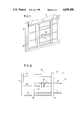
- FIG. 1 there is shown, in perspective means, the inventive barrier apparatus with the locking means secured thereto.
- FIG. 2 is a front elevational view of the gridwork panels of the barrier apparatus and locking means.
- FIG. 3 is an enlarged view of the locking apparatus of FIGS. 1 and 2.
- FIG. 4 is a view of a second embodiment of a locking means for the barrier apparatus.
- FIG. 5 is an enlarged view of the locking means of FIG. 4.
- FIG. 6 is an axial plane view of the locking means of FIG. 4.
- FIG. 7 is a front elevational view showing the extension elements of the barrier apparatus.
- FIG. 8 is a side planned view taken along line 8--8 of FIG. 7.
- FIGS. 1 and 2 there is shown a barrier apparatus 10 disposed within a framed vertically adjustable rectangular window 8.
- the barrier apparatus exhibits and adjustable horizontal length for insertion into a window casement 9 of said rectangular window 8, within which said barrier apparatus is slideably positionable.
- the barrier apparatus 10 comprises a first and second gridwork panels (see FIG. 2) horizontally spaced and in substantially co-planar juxtaposition. Said panels comprise rigid rectangular frames adapted to border and support said first and second panels.
- the first gridwork panel comprises a horizontally disposed upper border 14 and a lower border 16, as well as an outer vertically oriented side border 11 and inner vertically oriented side border 19.
- the second gridwork panel comprises horizontally disposed upper border 15 and horizontally disposed lower border 17 and, as well, comprises inner vertically oriented side border 18 and outer vertically oriented side border 12. Said inner side borders 18 and 19 are parallel and face each other. Further, said facing said borders 18 and 19 are provided with vertically spaced guide holes (see FIG. 1).
- first horizontally directed posts 24 and second horizontally directed post 25 are medially disposed between the respective lower and upper borders of the respective gridwork panels.
- Said posts 24 and 25 are affixed to facing inner side borders 18 and 19 respectively and are adapted to slideably penetrate through said side holes in order to thereby permit the slideably positionability of said first gridwork panel relative to said second gridwork panel
- Said horizontally directed posts 24 and 25 are uniformly spaced and are provided with pairs of notches 45 thereupon.
- locking means 30 which serve to mutually secure said first and second horizontal posts 24 and 25.
- Said locking means are provided with a pair of parallel cylindrical apertures having internal tumbler structure which are complemental to said notches 45.
- the locking means 30 may be selectively advanced relative to posts 24 and 25 to a position suitable for locking after first and second gridwork panels have been horizontally extended to the desired position relative to casement 9.
- Key 31 is employed to lock locking means 31 at such desired position. This is particularly shown in FIG. 3.
- the locking means comprises a wing nut 140 and washer 142 wherein said washer threadably encircles a threaded post 115.
- the extend of horizontal extension of first gridwork panel relative to second gridwork panel is delimited by the position which wing nut 140 is locked.
- post 18 is provided with at least one aperture which is suitable for co-alignment with radial apertures 144 of said washer 142. Once such co-alignment is achieved, the shank of padlock 130 may be placed between said radial aperture 144 and said aperture placed within said vertical side border 18. This may be more clearly seen in the enlarged view of FIGS. 5 and 6.
- element 32 which integrally extends upward from the left-hand border 20 of first gridwork panel.
- a similar extension element 33 extends from right-hand border 21 of second gridwork panel.
- Such extension elements are adapted to wedge between said window casement 9 and the framed horizontal window 8 such that extension elements 32 and 33 will secure the inventive barrier apparatus in position within the window casing relative to the window when the same is closed vertically downward on the top border 15 of said barrier apparatus.
Landscapes
- Engineering & Computer Science (AREA)
- Structural Engineering (AREA)
- Architecture (AREA)
- Civil Engineering (AREA)
- Power-Operated Mechanisms For Wings (AREA)
Abstract
The invention relates to a barrier apparatus for a framed vertically adjustable rectangular window, the apparatus having an adjustable length for insertion into a window casement of the window. It is slideably positionable within the casement. The barrier apparatus includes a first and a second gridwork panel horizontally spaced on co plan juxtaposition; the panels are rigid rectangular frames adapted to border and support the panels, each frame having horizontally disposed upper and lower borders, and inner and outer vertically oriented side borders, the inner side borders facing each other, the facing side borders having vertically spaced guide holes. Also provided are first and second horizontally directed posts affixed between the upper and lower horizontal borders of each panel, such posts affixed to the facing inner side borders and adapted to slideably penetrate the guide holes, the horizontally directed posts having uniformly spaced pairs of notches.
Description
This application is a continuation-in-part of application Ser. No. 224,673, filed July 27, 1988, now U.S. Pat. No. 4,837,974, which is a continuation-in-part of application Ser. No. 948,204, filed Dec. 31, 1986, abandoned, which is a continuation-in-part of application Ser. No. 854,428, filed Apr. 21, 1986, now U.S. Pat. No. 4,680,890.
This invention concerns an apparatus for the prevention of unauthorized entry by a person into a building and, more particularly, concerns a barrier apparatus of adjustable dimensions which may be removably inserted into the framework of an open window of a building to prevent passage therethrough.
In residential and industrial buildings, windows capable of opening and closing, and having transparent panels, serve to permit entrance of sunlight and passage of air, and function and emergency exits in case of fire. However, when such windows are open, the security of the building is threatened because of the relative ease with which an intruder may enter through the open window.
Various devices have been disclosed for thwarting unauthorized entrance through an open window while still retaining most of the functionality of the window. Such devices, however, have not heretofore been entirely successful. For complete effectiveness, the barrier device should be capable of easy installation into, and rapid removal from, variously sized window casements while being non-removable by a would-be intruder. The barrier should furthermore provide minimal occlusion of the area it occupies while having sufficient strength to resist forceful breakage.
The pertinent prior art, as best known to the inventor, is reflected in unpatented products knows as (1) WIND-O-GUARD, produced by The Leslie Lock Company of Atlanta, Ga. 30339 and (2) BURGLAR BARS, produced by Sterling Hardware Corp. of Richmond, Ill. 60071. The instant invention also represents an improvement over may U.S. Pat. Nos. 4,532,734 and 4,573,285, and over U.S. Pat. Nos. 2.508,302 and 4,437,265.
The invention relates to a barrier apparatus for a framed vertically adjustable rectangular window, the apparatus having an adjustable length for insertion into a window casement of such window. The apparatus is slideably positionable within such casement. Said barrier apparatus, comprises a first and a second gridwork panel horizontally spaced in substantially co-planar juxtaposition, said panels comprising rigid rectangular frames adapted to border and support said panels, each frame comprising horizontally disposed upper and lower borders, and inner and outer vertically oriented side borders, said inner side borders facing each other, said facing side borders having vertically spaced guide holes.
Further provided are first and second horizontally directed posts affixed medially between said upper and lower horizontal borders of each panel, said posts affixed to said facing inner sideborders and adapted to slideably penetrate said guide holes, said horizontally directed posts having a plurality of uniformly spaced pairs of notches thereon.
Yet further provided are locking means for mutually securing said first and second horizontal posts relative to each other, said locking means having a pair of parallel cylindrical apertures having internal surfaces for complemental slideably contact with said notched pairs of said horizontal posts, thereby defining the vertical extent of slideable horizontal length of said barrier apparatus.
It is an object to provide a modified slideably positionable window guard such that the window may be opened to permit passage of air therethrough while preventing the entry of an intruder.
It is another object to provide a barrier apparatus of an adjustable horizontal size capable of facile insertion into the rectangular space of the window casement of an open vertically slideable window.
It is a further object to provide a barrier apparatus having the above advantages, that can be readily removed by a user but not readily removed by a would-be intruder.
It is a yet further object to provide a barrier apparatus of the above nature having durable construction which, nonetheless, may be economically manufactured.
The above and yet other advantages of the present invention will become apparent from the hereinafter set forth Detailed Description of the Invention, the Drawings, and Claims appended herewith.
With regard to
FIG. 1 there is shown, in perspective means, the inventive barrier apparatus with the locking means secured thereto.
FIG. 2 is a front elevational view of the gridwork panels of the barrier apparatus and locking means.
FIG. 3 is an enlarged view of the locking apparatus of FIGS. 1 and 2.
FIG. 4 is a view of a second embodiment of a locking means for the barrier apparatus.
FIG. 5 is an enlarged view of the locking means of FIG. 4.
FIG. 6 is an axial plane view of the locking means of FIG. 4.
FIG. 7 is a front elevational view showing the extension elements of the barrier apparatus.
FIG. 8 is a side planned view taken along line 8--8 of FIG. 7.
With reference to FIGS. 1 and 2, there is shown a barrier apparatus 10 disposed within a framed vertically adjustable rectangular window 8. The barrier apparatus exhibits and adjustable horizontal length for insertion into a window casement 9 of said rectangular window 8, within which said barrier apparatus is slideably positionable.
The barrier apparatus 10 comprises a first and second gridwork panels (see FIG. 2) horizontally spaced and in substantially co-planar juxtaposition. Said panels comprise rigid rectangular frames adapted to border and support said first and second panels. The first gridwork panel comprises a horizontally disposed upper border 14 and a lower border 16, as well as an outer vertically oriented side border 11 and inner vertically oriented side border 19.
The second gridwork panel comprises horizontally disposed upper border 15 and horizontally disposed lower border 17 and, as well, comprises inner vertically oriented side border 18 and outer vertically oriented side border 12. Said inner side borders 18 and 19 are parallel and face each other. Further, said facing said borders 18 and 19 are provided with vertically spaced guide holes (see FIG. 1).
Between upper and lower horizontal borders are disposed first horizontally directed posts 24 and second horizontally directed post 25. These are medially disposed between the respective lower and upper borders of the respective gridwork panels.
Said posts 24 and 25 are affixed to facing inner side borders 18 and 19 respectively and are adapted to slideably penetrate through said side holes in order to thereby permit the slideably positionability of said first gridwork panel relative to said second gridwork panel
Said horizontally directed posts 24 and 25 are uniformly spaced and are provided with pairs of notches 45 thereupon.
There is further provided locking means 30 which serve to mutually secure said first and second horizontal posts 24 and 25. Said locking means are provided with a pair of parallel cylindrical apertures having internal tumbler structure which are complemental to said notches 45. Thereby, the locking means 30 may be selectively advanced relative to posts 24 and 25 to a position suitable for locking after first and second gridwork panels have been horizontally extended to the desired position relative to casement 9. Key 31 is employed to lock locking means 31 at such desired position. This is particularly shown in FIG. 3.
With reference to FIGS. 4 to 6, there is shown a second embodiment of the locking means. In this embodiment, the locking means comprises a wing nut 140 and washer 142 wherein said washer threadably encircles a threaded post 115. Through this mechanism, the extend of horizontal extension of first gridwork panel relative to second gridwork panel is delimited by the position which wing nut 140 is locked.
In addition, post 18 is provided with at least one aperture which is suitable for co-alignment with radial apertures 144 of said washer 142. Once such co-alignment is achieved, the shank of padlock 130 may be placed between said radial aperture 144 and said aperture placed within said vertical side border 18. This may be more clearly seen in the enlarged view of FIGS. 5 and 6.
With reference to FIG. 7, there is shown element 32 which integrally extends upward from the left-hand border 20 of first gridwork panel. A similar extension element 33 extends from right-hand border 21 of second gridwork panel. Such extension elements are adapted to wedge between said window casement 9 and the framed horizontal window 8 such that extension elements 32 and 33 will secure the inventive barrier apparatus in position within the window casing relative to the window when the same is closed vertically downward on the top border 15 of said barrier apparatus.
While there has been herein shown and described the preferred embodiments of the present invention, it is to be understood the invention may be embodied otherwise than is herein illustrated and described and that in said embodiments, certain changes in the detailed construction, and in the form and arrangement of parts may be made without departing from the underlying idea or principles of this invention within the scope of the appended claims.
Claims (5)
1. A barrier apparatus for a framed vertically adjustable rectangular window, the apparatus having an adjustable length for insertion into a window casement of said window, said apparatus slideably positionable within said casement, said barrier apparatus, comprising:
(a) a first and a second gridwork panel in horizontally spaced co-planar juxtaposition, said panels comprising rigid rectangular frames adapted to border and support said panels, each frame comprising horizontally disposed upper and lower borders, and inner and outer vertically oriented side borders said inner side borders facing each other, said facing side borders having vertically spaced guide holes;
(b) first and second horizontally directed posts affixed medially between said upper and lower horizontal borders of each panel, said posts affixed to said facing inner sideborders and adapted to post through said guide hole, said horizontally directed posts having a plurality of co-vertically spaced pairs of notches thereon;
(c) locking means for mutually securing said first and second horizontal posts relative to each other, said locking means having a pair of parallel cylindrical apertures having internal surfaces for complemental contact with said notched pairs of said horizontal post, thereby defining the horizontal extend of slideable horizontal length of said barrier apparatus.
2. The barrier apparatus recited in claim 1, further comprising extension element integrally extending upward from the left hand border of said first gridwork panel and from the right hand side panel said second gridwork panel, said extension element adapted to wedge between said window casement and in the framed horizontal window therein, such that said extension element will secure the barrier apparatus in position within the window casement and relative to the frame rectangular window when closed vertically downward on the top border of said barrier apparatus.
3. The barrier apparatus for a vertically adjustable window, the apparatus having an adjustable length adapted for insertion into a window casement below a framed rectangular window slideably positionable within said casement, the barrier apparatus comprising;
(a) a first and second gridwork panel horizontally spaced in substantially co-planar juxtaposition, said panels comprising rigid rectangular frames adapted to border and support said panels, each frame comprising horizontally disposed upper and lower borders, and inner and outer vertically oriented side borders, said inner side borders facing each other, said facing side borders having vertically spaced side holes.
(b) first and second horizontally directed posts affixed medially between upper and lower borders of each panels, said posts affixed to said facing inner side borders adapted to post through guide holes, one of said horizontally directed posts having a threaded exterior surface; and
(c) locking means comprising a wing nut and a washer, said washer threadably encircling said threaded post, said washer having a plurality of radially disposed apertures, said washer located between said wing nut and one of said vertically inner side border whereby said threaded posts may be secured to said vertical inner side borders through a rotational advancement of said wing nut upon said one of said horizontal post having threaded extension surface.
4. The barrier apparatus as recited in claim 3 further comprising further locking means comprising a padlock, the shank of which is placed through a horizontal aperture of one of said vertical side borders, thereby providing a redundant locking capability for the barrier apparatus.
5. The barrier apparatus as recited in claim 4 further comprising extension element integrally extending upward from the lefthand border of said first gridwork panel and from the righthand side panel said second gridwork panel, said extension element adapted to wedge between said window casement and the framed horizontal window therein, such that said extension element will secure the barrier apparatus in position within the window casement and relative to the frame rectangular window when closed vertically downward on the top border of said barrier apparatus.
Priority Applications (1)
| Application Number | Priority Date | Filing Date | Title |
|---|---|---|---|
| US07/313,772 US4899490A (en) | 1986-04-21 | 1989-02-21 | Window intrusion Barrier "B" |
Applications Claiming Priority (4)
| Application Number | Priority Date | Filing Date | Title |
|---|---|---|---|
| US06/854,428 US4680890A (en) | 1986-04-21 | 1986-04-21 | Window intrusion barrier |
| US94820486A | 1986-12-31 | 1986-12-31 | |
| US07/224,673 US4837974A (en) | 1986-04-21 | 1988-07-27 | Window instrusion barrier |
| US07/313,772 US4899490A (en) | 1986-04-21 | 1989-02-21 | Window intrusion Barrier "B" |
Related Parent Applications (1)
| Application Number | Title | Priority Date | Filing Date |
|---|---|---|---|
| US07/224,673 Continuation-In-Part US4837974A (en) | 1986-04-21 | 1988-07-27 | Window instrusion barrier |
Publications (1)
| Publication Number | Publication Date |
|---|---|
| US4899490A true US4899490A (en) | 1990-02-13 |
Family
ID=27499371
Family Applications (1)
| Application Number | Title | Priority Date | Filing Date |
|---|---|---|---|
| US07/313,772 Expired - Fee Related US4899490A (en) | 1986-04-21 | 1989-02-21 | Window intrusion Barrier "B" |
Country Status (1)
| Country | Link |
|---|---|
| US (1) | US4899490A (en) |
Cited By (16)
| Publication number | Priority date | Publication date | Assignee | Title |
|---|---|---|---|---|
| US5070647A (en) * | 1991-04-19 | 1991-12-10 | Spialter Millard L | Adjustable guard assembly with resilient release mechanism |
| US5339567A (en) * | 1993-06-22 | 1994-08-23 | Pierpont John M | Interior-mounted security bars |
| US5446996A (en) * | 1989-06-29 | 1995-09-05 | Lamont; Tim | Portable security grill apparatus |
| US5916074A (en) * | 1996-03-13 | 1999-06-29 | Tracy; Michael L. | Child safety window guard |
| WO2009042957A2 (en) | 2007-09-26 | 2009-04-02 | Indentiv, Llc | Methods, devices, systems, assemblies, and kits for tissue retraction in an oral cavity |
| US20090302287A1 (en) * | 2008-06-05 | 2009-12-10 | Tim Langan | Child safety device for balustrades |
| US7832455B1 (en) | 2006-11-24 | 2010-11-16 | Johnston Lorne G | Vehicle window security screen system |
| US8443550B1 (en) * | 2011-04-12 | 2013-05-21 | Prime-Line Products Company, Inc. | Window guard |
| USD737964S1 (en) | 2014-03-14 | 2015-09-01 | Ultradent Products, Inc. | Cheek retractor device |
| USD763444S1 (en) | 2014-03-14 | 2016-08-09 | Ultradent Products, Inc. | Cheek retractor device |
| US9470019B1 (en) | 2016-01-16 | 2016-10-18 | Roger Davis | Method and apparatus for improved gate lock |
| US9688291B1 (en) * | 2015-04-06 | 2017-06-27 | Fps Investments, Llc | Safety gate for rail car |
| USD792590S1 (en) | 2015-07-21 | 2017-07-18 | Ultradent Products, Inc. | Cheek retractor device |
| US9901332B2 (en) | 2013-03-15 | 2018-02-27 | Ultradent Products, Inc. | Cheek retractor device and method |
| US20190100944A1 (en) * | 2017-10-02 | 2019-04-04 | Roswitha Loudenslager | Bar Security System |
| USD914214S1 (en) | 2019-06-03 | 2021-03-23 | Ultradent Products, Inc. | Dental retraction device |
Citations (8)
| Publication number | Priority date | Publication date | Assignee | Title |
|---|---|---|---|---|
| US1451172A (en) * | 1921-10-27 | 1923-04-10 | Grover C F Mayer | Window guard |
| US2508302A (en) * | 1944-05-24 | 1950-05-16 | Stue Tryggve Bob | Portable clamp lock |
| US2775001A (en) * | 1953-05-05 | 1956-12-25 | Carrier Corp | Window locking assembly |
| US2819500A (en) * | 1956-08-31 | 1958-01-14 | Saber Charles | Window guard |
| US4170885A (en) * | 1976-06-21 | 1979-10-16 | Lundgren Calvin Q | Sliding door lock |
| US4394805A (en) * | 1981-04-24 | 1983-07-26 | Napper Roger L | Escapable-window-security-guard system |
| US4437265A (en) * | 1982-03-01 | 1984-03-20 | Jerome Turro | Safety guard |
| US4680890A (en) * | 1986-04-21 | 1987-07-21 | Isidore Jokel | Window intrusion barrier |
-
1989
- 1989-02-21 US US07/313,772 patent/US4899490A/en not_active Expired - Fee Related
Patent Citations (8)
| Publication number | Priority date | Publication date | Assignee | Title |
|---|---|---|---|---|
| US1451172A (en) * | 1921-10-27 | 1923-04-10 | Grover C F Mayer | Window guard |
| US2508302A (en) * | 1944-05-24 | 1950-05-16 | Stue Tryggve Bob | Portable clamp lock |
| US2775001A (en) * | 1953-05-05 | 1956-12-25 | Carrier Corp | Window locking assembly |
| US2819500A (en) * | 1956-08-31 | 1958-01-14 | Saber Charles | Window guard |
| US4170885A (en) * | 1976-06-21 | 1979-10-16 | Lundgren Calvin Q | Sliding door lock |
| US4394805A (en) * | 1981-04-24 | 1983-07-26 | Napper Roger L | Escapable-window-security-guard system |
| US4437265A (en) * | 1982-03-01 | 1984-03-20 | Jerome Turro | Safety guard |
| US4680890A (en) * | 1986-04-21 | 1987-07-21 | Isidore Jokel | Window intrusion barrier |
Cited By (24)
| Publication number | Priority date | Publication date | Assignee | Title |
|---|---|---|---|---|
| US5446996A (en) * | 1989-06-29 | 1995-09-05 | Lamont; Tim | Portable security grill apparatus |
| US5070647A (en) * | 1991-04-19 | 1991-12-10 | Spialter Millard L | Adjustable guard assembly with resilient release mechanism |
| US5339567A (en) * | 1993-06-22 | 1994-08-23 | Pierpont John M | Interior-mounted security bars |
| US5916074A (en) * | 1996-03-13 | 1999-06-29 | Tracy; Michael L. | Child safety window guard |
| US7832455B1 (en) | 2006-11-24 | 2010-11-16 | Johnston Lorne G | Vehicle window security screen system |
| WO2009042957A2 (en) | 2007-09-26 | 2009-04-02 | Indentiv, Llc | Methods, devices, systems, assemblies, and kits for tissue retraction in an oral cavity |
| US10307049B2 (en) | 2007-09-26 | 2019-06-04 | Ultradent Products, Inc. | Methods, devices, systems, assemblies, and kits for tissue retraction in an oral cavity |
| EP3552535A1 (en) | 2007-09-26 | 2019-10-16 | Ultradent Products, Inc. | Methods, devices, systems, assemblies, and kits for tissue retraction in an oral cavity |
| US9387054B2 (en) | 2007-09-26 | 2016-07-12 | Ultradent Products, Inc. | Methods, devices, systems, assemblies, and kits for tissue retraction in an oral cavity |
| US20090302287A1 (en) * | 2008-06-05 | 2009-12-10 | Tim Langan | Child safety device for balustrades |
| US8443550B1 (en) * | 2011-04-12 | 2013-05-21 | Prime-Line Products Company, Inc. | Window guard |
| US9901332B2 (en) | 2013-03-15 | 2018-02-27 | Ultradent Products, Inc. | Cheek retractor device and method |
| US10016258B2 (en) | 2013-03-15 | 2018-07-10 | Ultradent Products, Inc. | Cheek and lip expansion device and method |
| USD737964S1 (en) | 2014-03-14 | 2015-09-01 | Ultradent Products, Inc. | Cheek retractor device |
| USD761958S1 (en) | 2014-03-14 | 2016-07-19 | Ultradent Products, Inc. | Cheek retractor device |
| USD763444S1 (en) | 2014-03-14 | 2016-08-09 | Ultradent Products, Inc. | Cheek retractor device |
| USD820445S1 (en) | 2014-03-14 | 2018-06-12 | Ultradent Products, Inc. | Cheek retractor device |
| US9688291B1 (en) * | 2015-04-06 | 2017-06-27 | Fps Investments, Llc | Safety gate for rail car |
| USD792590S1 (en) | 2015-07-21 | 2017-07-18 | Ultradent Products, Inc. | Cheek retractor device |
| US9470019B1 (en) | 2016-01-16 | 2016-10-18 | Roger Davis | Method and apparatus for improved gate lock |
| US20190100944A1 (en) * | 2017-10-02 | 2019-04-04 | Roswitha Loudenslager | Bar Security System |
| US10689885B2 (en) * | 2017-10-02 | 2020-06-23 | Roswitha Loudenslager | Bar security system |
| USD914214S1 (en) | 2019-06-03 | 2021-03-23 | Ultradent Products, Inc. | Dental retraction device |
| USD964566S1 (en) | 2019-06-03 | 2022-09-20 | Ultradent Products, Inc. | Dental retraction device |
Similar Documents
| Publication | Publication Date | Title |
|---|---|---|
| US4899490A (en) | Window intrusion Barrier "B" | |
| US4175357A (en) | Protective enclosure for building openings | |
| US4587759A (en) | Locking window assembly | |
| US4389817A (en) | Double door assembly | |
| US4279137A (en) | Security device | |
| CA2181906A1 (en) | Alarm-triggering locking device for the catch and/or hinge region of a door or window to be protected | |
| US3271063A (en) | Door guard | |
| US5832666A (en) | Window storm shield and guard assembly | |
| US4059923A (en) | Security window guard | |
| US3820285A (en) | Blocking device for locking sliding closures | |
| US4680890A (en) | Window intrusion barrier | |
| US4653226A (en) | Window security unit | |
| US3414306A (en) | Door knob, lock and slide bolt protector | |
| US4400912A (en) | Patio door and window guard system | |
| US4837974A (en) | Window instrusion barrier | |
| US3224048A (en) | Removable safety bar for windows, doors and the like | |
| US5862645A (en) | Burglarproof sash window | |
| US4848030A (en) | Removable window guard assembly | |
| DE3936084A1 (en) | Safe deposit with readily breakable alarm current conductors | |
| US6837082B1 (en) | Door security system | |
| US5893235A (en) | Removable security apparatus for building openings | |
| US5392570A (en) | Security bar assembly | |
| GB2290336A (en) | Door or window security device | |
| US5740628A (en) | Removable security apparatus for building openings | |
| US4079972A (en) | Portable door bar |
Legal Events
| Date | Code | Title | Description |
|---|---|---|---|
| REMI | Maintenance fee reminder mailed | ||
| LAPS | Lapse for failure to pay maintenance fees | ||
| FP | Lapsed due to failure to pay maintenance fee |
Effective date: 19940213 |
|
| STCH | Information on status: patent discontinuation |
Free format text: PATENT EXPIRED DUE TO NONPAYMENT OF MAINTENANCE FEES UNDER 37 CFR 1.362 |