US4896431A - Alignment apparatus - Google Patents
Alignment apparatus Download PDFInfo
- Publication number
- US4896431A US4896431A US07/266,071 US26607188A US4896431A US 4896431 A US4896431 A US 4896431A US 26607188 A US26607188 A US 26607188A US 4896431 A US4896431 A US 4896431A
- Authority
- US
- United States
- Prior art keywords
- shaft
- pin
- members
- terminal body
- lock
- Prior art date
- Legal status (The legal status is an assumption and is not a legal conclusion. Google has not performed a legal analysis and makes no representation as to the accuracy of the status listed.)
- Expired - Lifetime
Links
Images


Classifications
-
- B—PERFORMING OPERATIONS; TRANSPORTING
- B23—MACHINE TOOLS; METAL-WORKING NOT OTHERWISE PROVIDED FOR
- B23P—METAL-WORKING NOT OTHERWISE PROVIDED FOR; COMBINED OPERATIONS; UNIVERSAL MACHINE TOOLS
- B23P19/00—Machines for simply fitting together or separating metal parts or objects, or metal and non-metal parts, whether or not involving some deformation; Tools or devices therefor so far as not provided for in other classes
- B23P19/10—Aligning parts to be fitted together
- B23P19/102—Aligning parts to be fitted together using remote centre compliance devices
-
- B—PERFORMING OPERATIONS; TRANSPORTING
- B25—HAND TOOLS; PORTABLE POWER-DRIVEN TOOLS; MANIPULATORS
- B25J—MANIPULATORS; CHAMBERS PROVIDED WITH MANIPULATION DEVICES
- B25J17/00—Joints
- B25J17/02—Wrist joints
- B25J17/0208—Compliance devices
Definitions
- the present invention relates to an alignment apparatus which is interposed between a machine main body such as a robot and a terminal body such as a finger device, a hand device, or the like, and performs alignment therebetween to have a predetermined compliance.
- Japanese Patent Publication No. 61-34932 discloses an apparatus which couples a robot main body and a finger device using a plurality of leaf springs, and utilizes elasticity of these leaf springs.
- Japanese Patent Laid-Open (Kokai) Nos. 57-168840 and 62-103990, and U.S. Pat. No. 3,824,674 disclose arrangements wherein a robot main body and a finger device are coupled using coil springs in place of the leaf springs.
- the alignment apparatus is required to have an arrangement of allowing deviations of the robot and the finger device and of recovering the deviations.
- U.S. Pat. Nos. 4,609,325, 4,179,783 and 4,098,001 disclose arrangements in which deviations of the robot and the finger device are allowed and recovered using a bearing means and an elastic member.
- Such conventional alignment apparatuses employ springs having directivity of deviation. For this reason, the deviating direction of the finger device is limited.
- the conventional alignment apparatus in order to carry out a precise alignment operation, the arrangement becomes complicated.
- An assembly operation of articles by a robot has merit since it can be performed at high speed and high precision within a unit time.
- assembly positions of an article gripped by the finger device and a corresponding member are shifted from each other.
- the finger device is deviated relative to a robot arm to execute the assembly operation.
- the finger device is recovered to an original position.
- the time required for the recovery operation of the finger device and the time required for completely stopping the finger device are preferably short. In particular, if the stopping time is long, the next operation of the robot becomes unstable.
- the present invention has been made in consideration of the above situation, and has as its main object to provide an alignment apparatus capable of precisely performing an assembly operation even if assembly positions of a gripped article and a corresponding member do not coincide with each other, and even if their central positions are offset from each other when an article is gripped by a finger device and a robot is moved to an assembly position of the article to assemble the article in a corresponding member.
- an alignment apparatus which is interposed between a machine body and a terminal body attached to the machine body.
- the alignment apparatus performs alignment therebetween with a predetermined compliance, and comprises: a mounting body connected to the machine body, the mounting body and the terminal body having opposing surfaces; a first shaft member engaged with an engaging portion formed on the opposing surface of the mounting body; a second shaft member engaged with an engaging portion formed on the opposing surface of the terminal body, the second shaft member being located on an identical axis to the first shaft member; a plurality of pin members disposed around the first and second shaft members to surround the first and second shaft members; and compression means for applying a tightening force to the plurality of pin members.
- an alignment apparatus which is interposed between a machine body and a terminal body attached to the machine body.
- the alignment body performs alignment therebetween with a predetermined compliance, and comprises: a first shaft portion connected to the machine body; a second shaft portion connected to the terminal body; a plurality of pin members disposed to surround outer surfaces of the first and second shaft portions; and compression means for applying a tightening force toward the center of the first and second shaft portions to the pin members.
- FIG. 1 is a longitudinal sectional view showing an arrangement of a first embodiment of an alignment apparatus according to the present invention in a state wherein the apparatus is attached to the distal end of a robot arm;
- FIG. 2 is a cross-sectional view taken along a line II--II of the alignment apparatus shown in FIG. 1;
- FIG. 3 is a plan view showing an offset state between a pin and a fitting hole on an x-y plane
- FIG. 4A is a partial front view showing a state wherein first and second shaft members are aligned with each other;
- FIG. 4B is a partial front view showing a state wherein the first and second shaft members are deviated from each other so as to absorb an offset between the pin and the fitting hole;
- FIG. 5 is a longitudinal sectional view showing an arrangement of a modification of the alignment apparatus of the first embodiment in a state wherein the apparatus is attached to the distal end of the robot arm;
- FIG. 6 is a cross-sectional view taken along a line VI--VI of the alignment apparatus shown in FIG. 5;
- FIG. 7 is a longitudinal sectional view showing the alignment apparatus shown in FIG. 5 in a state wherein its lock mechanism performs a locking operation;
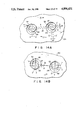
- FIG. 8 is a longitudinal sectional view showing an arrangement of a second embodiment of an alignment apparatus according to the present invention in a state wherein the apparatus is attached to the distal end of the robot arm;
- FIG. 9 is a cross-sectional view taken along a line IX--IX of the alignment apparatus shown in FIG. 8;
- FIG. 10 is a plan view showing an offset state between a pin and a fitting hole on an x-y plane
- FIG. 11A is a partial front view showing a state wherein first and second shaft members are aligned with each other;
- FIG. 11B is a partial front view showing a state wherein the first and second shaft members are deviated from each other so as to absorb an offset between the pin and the fitting hole;
- FIG. 12 is a longitudinal sectional view showing an arrangement of a modification of the alignment apparatus of the second embodiment in a state wherein the apparatus is attached to the distal end of the robot arm;
- FIG. 13 is a cross-sectional view taken along a line XIII--XIII of the alignment apparatus shown in FIG. 12;
- FIG. 14A is a plan view showing a case wherein two shafts are deviated in a parallel state
- FIG. 14B is a plan view showing a case wherein two shafts are deviated in a point symmetrical state
- FIG. 15 is a longitudinal sectional view showing an arrangement of a third embodiment of an alignment apparatus according to the present invention in a state wherein the apparatus is attached to the distal end of a robot arm;
- FIG. 16 is a cross-sectional view taken along a line XVI--XVI of the alignment apparatus shown in FIG. 15;
- FIG. 17 is a plan view showing an offset state between a pin and a fitting hole on an x-y plane
- FIG. 18A is a partial front view showing a state wherein first and second shaft members are aligned with each other.
- FIG. 18B is a partial front view showing a state wherein the first and second shaft members are deviated from each other so as to absorb an offset between the pin and the fitting hole.
- FIG. 1 shows a state wherein a hand portion 14 is attached to the distal end of a robot arm 10 constituting a part of an automatic assembly apparatus through an alignment apparatus 12 of the first embodiment.
- the robot arm 10 can be freely moved in a right-and-left direction (x-direction) in FIG. 1, a direction perpendicular to the drawing surface (y-direction), and an up-and-down direction (z-direction) by a drive mechanism (not shown).
- the hand portion 14 comprises a hand body 16 which has an upper circular opening portion having a first diameter in the upper surface and in which a cylindrical hollow portion having a second diameter larger than the first diameter is formed, and a holding member 20 fixed to the lower surface of the hand body 16 through a bolt 18.
- An insertion hole 24 in which a round-rod pin 22 is inserted as a fitting member and which extends vertically and is open to the lower surface of the holding member 20 is formed in the lower portion of the holding member 20.
- a suction pipe 26 connected to a suction pump (not shown) communicates with and is connected to the upper portion of the insertion hole 24. Upon driving of the suction pump, the interior of the insertion hole 24 is maintained in a negative pressure state, and the pin 22 is drawn by suction in the insertion hole 24 by the negative pressure.
- a fitting hole 28 in which the pin 22 is fitted is formed in a substrate 30 as a receiving member.
- the substrate 30 is horizontally chucked on a base (not shown). In this state, the fitting hole 28 extends vertically.
- a tapered surface 32 having a predetermined slope with respect to a horizontal plane is formed on the upper peripheral edge of the fitting hole 28 to facilitate insertion of the pin 22.
- the alignment apparatus 12 of the first embodiment comprises a pair of compliance units 34 and 36 symmetrically disposed about the central axis of the robot arm 10.
- the alignment apparatus 12 comprises a disc-like mounting body 40 fixed to the lower end of the robot arm 10 through a bolt 38 and a support body 44 fixed to the lower surface of the mounting body 40 through a bolt 42.
- the support body 44 is constituted by a columnar portion 44a having a third diameter smaller than the first diameter described above at its central portion, and a flange portion 44b having a fourth diameter larger than the first diameter and smaller than the second diameter.
- the upper surface of the flange portion 44b is in contact with the upper surface of the hollow portion of the hand body 16 through a first ball bearing 46 to be pivotal and movable in a horizontal plane.
- the lower surface of the flange portion 44b is in contact with the lower surface of the hollow portion of the hand body 16 through a second ball bearing 48 to be pivotal and movable in the horizontal plane. In this manner, the holding member 20 is supported to be freely movable and pivotal in the horizontal plane with respect to the robot arm 10.
- the pair of compliance units 34 and 36 are set as follows. When no external force is applied to the holding member 20 in a normal state, the units 34 and 36 elastically maintain a state wherein the central axis of the robot arm 10 is aligned with the central axis of the holding member 20 in the vertical direction. When an external force in the horizontal plane is applied to the holding member 20, the units 34 and 36 allow flexible deviation in the horizontal plane within a predetermined range in accordance with the external force.
- the compliance units 34 and 36 are located on opposing positions on the circumference of an identical circle to have the central axis of the robot arm 10 as the center, in other words, on an identical diameter, as shown in FIG. 2, and have the same arrangement. For this reason, the arrangement of only the left compliance unit 34 in FIG. 2 will be described in detail, and a description of the arrangement of the right compliance unit 36 in FIG. 2 will be omitted by attaching similar suffixes to reference numerals of its components.
- the compliance unit 34 comprises a first shaft member 34a which is mounted on the lower surface of the mounting body 40 to project downward, and a second shaft member 34b which is mounted on the upper surface of the hand body 16 to project upward in a state wherein it is aligned with the first shaft member 34a in the vertical direction while no external force is applied to the holding member 20.
- the first and second shaft members 34a and 34b are formed to have outer circumferential surfaces having the same radii.
- the lower end of the first shaft member 34a opposes the upper end of the second shaft member 34b to be separated at a small distance.
- the compliance unit 34 comprises a plurality of support pins 34c as support members disposed to simultaneously surround the opposing end portions of the first and second shaft members 34a and 34b. More specifically, each support pin 34c is formed of a columnar body having the same radius as that of the first and second shaft members 34a and 34b. The number of the support pins 34c is six. The six support pins 34c are disposed to simultaneously surround the opposing end portions of the first and second shaft members 34a and 34b without any gap.
- Annular grooves 34d are formed in the upper and lower end portions of each support pin 34c.
- ring-shaped biasing members 34e for biasing these support pins to be elastically pressed against the circumferential surfaces at the opposing end portions of the first and second shaft members 34a and 34b are respectively housed in the grooves 34d to simultaneously surround these support pins 34c.
- each biasing member 34e is formed of a ring-shaped coil spring having a large number of turns.
- the robot arm 10 is controlled and moved by a control mechanism (not shown) so that the pin 22 is fitted in the fitting hole 28 formed in the substrate 30 while the pin 22 is chucked and held by the holding member 20. More specifically, position data of the fitting hole 28 on an x-y plane, and three-dimensional position of the robot arm 10, i.e., the position data of the pin 22 to be fitted are input beforehand in this control mechanism. The robot arm 10 is controlled and moved by the control operation of the control mechanism based on these position data.
- the robot arm 10 is moved according to the control content of the control mechanism, and the fitting hole 28 is aligned according to a setting value, the pin 22 is moved to a position immediately above the fitting hole 28, and is moved vertically downward, so that the pin 22 can be fitted in the fitting hole 28 without any problem.
- the positioning of the fitting hole 28 is often not accurate and the fitting hole is slightly offset from the setting value in the x-y plane or the position of the robot arm 10 is often slightly offset from a position defined by the control mechanism due to an error of a drive system, e.g., a backlash of gears.
- the first and second shaft members 34a; 34b and 36a; 36b are elastically aligned in the vertical direction by the pairs of upper and lower biasing members 34e; 36e, as shown in FIG. 4A.
- the horizontal partial force F acts on the pin 22 in this state, it acts on the second shaft members 34b and 36b of the compliance units 34 and 36 through the holding member 20 and the hand body 16.
- the support pins 34c; 36c are obliquely inclined against the biasing force of these biasing members 34e; 36e, so that the second shaft members 34b; 36b are moved and deviated in the horizontal direction, as shown in FIG. 4B.
- an offset between the pin 22 and the fitting hole 28 can be elastically absorbed by deviation of the first and second shaft members 34a; 34b and 36a; 36b of the compliance units 34 and 36, respectively, so that the pin 22 and the fitting hole 28 are vertically aligned. Therefore, upon downward movement of the robot arm 10, the pin 22 can be fitted in the fitting hole 28 smoothly.
- the pin 22 is chucked in the insertion hole 24 formed in the holding member 20 by vacuum suction.
- the present invention is not limited to this.
- the pin 22 can be magnetically chucked using a magnet or may be mechanically locked using mechanical fingers.
- the hand body 16 of the hand portion 14 and the support body 44 of the robot arm 10 are rotatably supported by the first and second bearings 46 and 48.
- the present invention is not limited to this arrangement.
- these components may be supported by air bearings.
- the ring-shaped coil springs are employed as the biasing members 34e and 36e.
- the present invention is not limited to this arrangement.
- ring-shaped elastic rubber bands may be employed.
- the grooves 34d and 36d need not be formed in the support pins 34c and 36c as compared to the case wherein the ring-shaped coil springs are used.
- the alignment apparatus 12 of the first embodiment mentioned above does not comprise a lock means. As shown in a modification of the first embodiment shown in FIGS. 5 to 7, the apparatus may have the lock means.
- the alignment apparatus 12 of this modification comprises a pair of lock mechanisms 50 and 52 as the lock means so as to prevent the hand body 16 from being deviated in a lateral direction with respect to the mounting body 40 due to its inertia when the robot arm 10 is moved at high speed in the lateral direction, as shown in FIG. 5.
- the lock mechanisms 50 and 52 are located to oppose each other on the circumference of the same circle as that of a circle along which the pair of compliance units 34 and 36 are disposed and on a diameter perpendicular to the predetermined diameter on which the compliance units 34 and 36 are located to have the central axis of the robot arm 10 as the center, and have the same arrangement, as shown in FIG. 6. For this reason, the arrangement of only the upper lock mechanism 50 in FIG. 6 will be described in detail below, and a description of the arrangement of the lower lock member 52 in FIG. 6 will be omitted by attaching similar suffixes to reference numerals of its components.
- the lock mechanism 50 comprises a cylinder chamber 50a which is assembled in the mounting body 40.
- a piston member 50b which is extendable downward is housed in the cylinder chamber 50a.
- the piston member 50b is biased upward by a coil spring 50c.
- a stopper member 50d is integrally formed on the upper end of the piston member 50b and can project upward by the biasing force of the coil spring 50c. At a position where the stopper member 50d abuts against the upper surface of the cylinder chamber 50a and is stopped, the retracted position of the piston member 50b is defined.
- a lock hole 50e in which the distal end of the corresponding piston member 50b is fitted is formed in the upper surface of the hand body 16 at a position opposing the distal end of the piston member 50b.
- a coupling pipe 50f coupled to a compression pump mechanism 56 through an electromagnetic valve 54 is connected to a portion of the cylinder chamber 50a above the upper end of the piston member 50b.
- the robot arm 10 is controlled and moved by a control mechanism (not shown) so that the pin 22 is fitted in the fitting hole 28 formed in the substrate 30 while the pin 20 is chucked and held by the holding member 20. More specifically, position data of the fitting hole 28 on an x-y plane, and three-dimensional position of the robot arm 10, i.e., the position data of the pin 22 to be fitted are input beforehand in this control mechanism. The robot arm 10 is controlled and moved by the control operation of the control mechanism based on these position data.
- the electromagnetic valve 54 is opened, and compressed air is supplied from the compression pump mechanism 56 to the lock mechanisms 50 and 52.
- the piston members 50b and 52b are pressed downward from their retracted positions against the biasing forces of the corresponding coil springs 50e and 52e, and are deviated to their lock positions, as shown in FIG. 7.
- the lock mechanisms 50 and 52 are actuated and the piston members 50b and 52b are brought to the lock positions to be fitted in the corresponding lock holes 50e and 52e, so that the hand body 16 and the mounting body 40 are laterally locked and laterally moved together.
- the electromagnetic valve 54 When the robot arm 10 is moved in the vertical direction, i.e., in the x-z or y-z plane under the movement control, the electromagnetic valve 54 is closed, and no compressed air is supplied from the compression pump mechanism 56 to the lock mechanisms 50 and 52. In this manner, the piston members 50b and 52b are pushed upward from the lock positions to the retracted positions by the biasing forces of the corresponding coil springs 50e and 52e, and are deviated to the retracted positions, as illustrated in FIG. 5.
- lock mechanisms 50 and 52 are deactivated, and the piston members 50b and 52b are brought to the retracted positions to be withdrawn from the corresponding lock holes 50e and 52e, so that the hand body 16 and the mounting body 40 are brought to a state wherein they can be freely moved relative to each other in the lateral direction.
- the pair of lock mechanisms 50 and 52 are arranged as the lock means, so that the hand portion 14 of the robot arm 10 can be integrally moved upon horizontal movement of the robot arm 10, thus preventing the hand portion 14 from being deviated.
- FIGS. 8 to 10 A second embodiment of an alignment apparatus according to the present invention will be described hereinafter with reference to FIGS. 8 to 10.
- FIG. 8 illustrates a state wherein hand portion 14 is attached to the distal end of a robot arm 10 mentioned above through an alignment apparatus 100 of the second embodiment.
- the alignment apparatus 100 of the second embodiment comprises a compliance unit 134 disposed to have a central axis coaxial with the central axis of the robot arm 10.
- the compliance unit 134 elastically maintains a state wherein the central axis of the robot arm 10 is aligned with the central axis of the holding member 20 in the vertical direction.
- the unit 134 allows flexible deformation in the horizontal plane within a predetermined range and inclination with respect to the vertical axis.
- the compliance unit 134 comprises a first shaft member 134a which is integrally formed on the lower surface of a mounting body 40 fixed to the lower end of the robot arm 10 to be coaxial with the central axis of the robot arm 10 and to extend downward.
- a second shaft member 134b is fixed to the upper surface of a hand body 16 through a bolt 38 to be coaxial with the central axis of the holding member 20 and to extend upward.
- the opposing end portions of the first and second shaft members 134a and 134b oppose each other to be separated at a predetermined distance.
- a piston member 138b projects downward from the lower surface of the first shaft member 134a.
- a suspending member 134c is mounted on the lower end of the piston member 138b.
- An outer flange portion 134d is integrally formed on the lower end of the suspending member 134c.
- a stepped through hole 134f in which the suspending member 134c is complementarily fitted is formed in the hand body 16.
- a coil spring 134g is interposed between the stepped portion of the second shaft member 134b defining the upper surface portion corresponding to the intermediate portion of the stepped through hole 134f and the outer flange portion 134d of the suspending member 134c.
- the coil spring 134g is arranged to elastically support the second shaft member 134b on the first shaft member 134a through the outer flange portion 134d and the suspending member 134c.
- the hand body 16 to which the second shaft member 134b is fixed is directly connected to the mounting body 40, to which the first shaft member 134a is mounted, so as to be elastically suspended.
- pivotal movement of the hand body 16 about the central axis of the mounting body 40 i.e., an inclining operation about the central axis is allowed.
- the compliance unit 134 comprises a plurality of support pins 134e disposed to simultaneously surround the opposing end portions of the first and second shaft members 134a and 134b.
- the first and second shaft members 134a and 134b and the support pins 134e have the same diameter.
- the number of the support pins 134e is six. These six support pins 134e are disposed to simultaneously surround the opposing end portions of the first and second shaft members 134a and 134b without any gap.
- Annular grooves 134h are formed in the upper and lower end portions of each support pin 134e.
- ring-shaped biasing members 134i for biasing these support pins 134e to be elastically pressed against the circumferential surfaces at the opposing end portions of the first and second shaft members 134a and 134b are respectively housed in the grooves 134h to simultaneously surround these support pins 134e, as shown in FIG. 9.
- each biasing member 134i is formed of a ring-shaped coil spring having a large number of turns.
- each support pin 134e is rounded.
- the upper and lower end portions of each support pin 134e are rotatably engaged with the lower surface of the mounting body 40 and the upper surface of the hand body 16 through ball bearings 134j and 134k, respectively.
- the alignment apparatus 100 comprises a lock mechanism 138 for preventing the second shaft member 134b from being laterally deviated with respect to the first shaft member 134a due to its inertia when the robot arm 10 is moved at high speed in the lateral direction.
- the lock mechanism 138 comprises a cylinder chamber 138a extending in the first shaft member 134a along its central axis.
- a piston member 138b is housed in the cylinder chamber 138a to be reciprocal along the central axis.
- the piston member 138b is biased downward by the coil spring 138c.
- the non-lock position of the piston member is defined.
- a tapered surface 138e tapered downward is formed on the stepped portion of the second shaft member 134b, which contacts the upper end of the coil spring 134g described above.
- a tapered surface 138f is formed on the edge portion of the outer flange portion 134d opposing the tapered surface 138e. The tapered surface 138f is engaged with the tapered surface 138e in a lifted state.
- a coupling pipe 138g coupled to a compression pump mechanism (not shown) is connected to a portion of the cylinder chamber 138a below the stepped portion 138d of the piston member 138b.
- the pin 22 is moved to a position immediately above the fitting hole 28, and is moved vertically downward, so that the pin 22 can be reliably fitted in the fitting hole 28.
- the fitting hole 28 is formed to be obliquely offset. If such an offset occurs, the lower edge the pin 22 which is moved downward upon downward movement of the robot arm 10 abuts against a tapered surface 32 of the fitting hole 28, as shown in FIGS. 8 and 10. When the robot arm 10 is further moved downward, the lower edge of the pin 22 receives a horizontal partial force F along the tapered surface 32.
- the first and second shaft members 134a and 134b are elastically aligned in the vertical direction by the pair of upper and lower biasing members 134i, as shown in FIG. 11A.
- the pin 22 receives the horizontal partial force F as described above, the partial force F acts on the second shaft member 134b of the compliance unit 134 through the holding member 20 and the hand body 16. From this state, the support pins 134e are obliquely inclined against the biasing forces of these biasing members 134i, so that the second shaft member 134b is moved and deviated in the horizontal direction, as shown in FIG. 11B.
- the first and second shaft members 134a and 134b are arranged to be relatively pivotal about the central axis.
- the second shaft member 134b can be temporarily flexibly inclined with respect to the first shaft member 134a with respect to an inclination ( ⁇ ) of the fitting hole 28 or the pin 22 from the central axis (z-axis).
- ⁇ inclination
- z-axis central axis
- An oblique offset between the pin 22 and the fitting hole 28 can be absorbed by deviation and inclination of the first and second shaft members 134a and 134b in the compliance unit 134, and the central axis of the pin 22 is aligned with that of the fitting hole 28.
- the pin 22 upon downward movement of the robot arm 10, the pin 22 can be reliably fitted in the fitting hole 28.
- the alignment apparatus 100 of the second embodiment can be deviated to have a compliance in correspondence with the inclination ( ⁇ ) with respect to the z-axis as well as an offset in the x- and y-directions, and when a partial force caused by such inclination or offset is canceled, it can be reliably recovered to an original aligned state.
- the single fitting hole 28 is formed in the substrate 30, and the single pin 22 is inserted and held by the holding member 20.
- the present invention is not limited to a fitting operation of a single shaft, but can be applied to a case of two shafts, i.e., wherein two pins 22 inserted and held by the holding member 20 are to be fitted in two fitting holes 28 formed in the substrate 30, respectively, as shown in a modification of the second embodiment in FIGS. 12 and 13.
- each support pin 134e is set to be considerably smaller than the diameter of the first and second shaft members 134a and 134b unlike the arrangement of the second embodiment.
- Six V-grooves 134m are formed at equal angular intervals in each of the end portions of the first and second shaft members 134a and 134b to extend vertically in correspondence with the number of support pins 134e, as best illustrated in FIG. 13.
- the support pins 134e are supported to be fitted in the V-grooves 134m formed in the first and second shaft members 134a and 134b, the relative angular positions of the first and second shaft members 134a and 134b are elastically defined.
- a compliance when the unit 134 is deviated to shift an angle in the horizontal plane (x-y plane) occurs as well as the compliance in the second embodiment. In this manner, even if a shift in angle ( ⁇ ) about the z-axis occurs, the compliance unit 134 can provide the compliance corresponding to the shift in angle ( ⁇ ).
- a pair of lock mechanisms 138 are disposed at symmetrical positions to have the central axis of the robot arm 10 as the center in order to provide a rotation lock function of the second shaft member 134b.
- the alignment apparatus 100 has compliances for offset along the x- and y-axes, an offset ( ⁇ ) in the rotational direction about the z-axis, and an inclination ( ⁇ ) with respect to the z-axis.
- the apparatus can be flexibly deviated with respect to an oblique offset, and when an offsetting force caused by the oblique offset is canceled, can be recovered to an original aligned state. In this manner, even if an offset occurs in a fitting operation of two shafts, the fitting operation can be reliably executed without posing a problem.
- the alignment operation in the case of two shafts can be similarly applied to a case wherein a member to be fitted in the case of one shaft does not have a circular section but a polygonal section.
- the compliance unit 134 has compliances for an offset ( ⁇ ) in the rotational direction about the z-axis and an inclination ( ⁇ ) with respect to the z-axis.
- FIGS. 15 to 18B A third embodiment of an alignment apparatus according to the present invention will be described hereinafter with reference to FIGS. 15 to 18B.
- FIG. 15 shows a state wherein a hand portion 14 is attached to the distal end of a robot arm 10 constituting a part of an automatic assembly apparatus through an alignment apparatus 200 of the third embodiment like in the first and second embodiments mentioned above.
- the alignment apparatus 200 of the third embodiment comprises a compliance mechanism 234 disposed to have a central axis coaxial with the central axis of the robot arm 10.
- the compliance mechanism 234 is arranged as follows. That is, when no external force is applied to a holding member 20 in a normal state, the mechanism 234 elastically maintains a state wherein the central axis of the robot arm 10 is aligned with the central axis of a holding member 20 in the vertical direction. When an external force in a horizontal plane acts on the holding member 20, the mechanism allows flexible deviation in the horizontal plane within a predetermined range in accordance with the external force.
- the compliance mechanism 234 comprises a first shaft member 234a which is integrally formed on the lower surface of a mounting body 40 fixed to the lower end of the robot arm 10 to be coaxial with the central axis of the robot arm 10 and to extend downward.
- a second shaft member 234b is fixed to the upper surface of a hand body 16 through a bolt 18 to be coaxial with the central axis of the holding member 20 and to project upward.
- the opposing end portions of the first and second shaft members 234a and 234b oppose each other to be separated at a predetermined distance.
- Outer flange portions 234c and 234d are integrally formed on the lower end of the first shaft member 234a and the upper end of the second shaft member 234b, respectively.
- the compliance mechanism 234 comprises a plurality of support pins 234e arranged to simultaneously surround the opposing end portions of the first and second shaft members 234a and 234b.
- Each support pin 234e comprises outer flanges 234f and 234g at its upper and lower end portions, respectively. More specifically, each of the outer flanges 234f and 234g of each support pin 234e is formed of a columnar body having a radius considerably smaller than that of the first and second shaft members 234a and 234b, and the flanges 234f and 234g each number six.
- a plurality of vertical V-grooves 234m are formed at equal angular intervals on the outer surfaces of the outer flange portions 234c and 234d of the first and second shaft members 234a and 234b in correspondence with the number of pins 234e, as shown in FIG. 16.
- the support pins 234e are supported and fitted in the corresponding V-grooves 234m. In this manner, the position of the second shaft member 234b relative to the first shaft member 234a is elastically defined.
- An annular groove 234h is formed in the outer surface of each support pin 234e, except for the outer flanges 234f and 234g.
- each support pin 234e is engaged from the above with the outer flange portion 234c of the first shaft portion 234a, and the outer flange 234g integrally formed on the lower end of each support pin 234e is engaged from the above with the outer flange portion 234d of the second shaft member 234b. In this manner, the hand body 16 is suspended from the mounting body 40 of the compliance mechanism 234 to be pivotal about the central axis.
- each biasing member 234i is formed of a ring-shaped coil spring having a large number of turns.
- opposing recesses 234j and 234k are respectively formed in the lower surface of the first shaft member 234a and the upper surface of the second shaft member 234b.
- a coil spring 234l is disposed while its upper and lower ends are housed in these recesses 234j and 234k, respectively.
- the coil spring 234l is arranged to bias the first and second shaft members 234a and 234b to be separated from each other.
- the alignment apparatus 200 comprises a lock mechanism 238 for preventing the second shaft member 234b from being laterally deviated with respect to the first shaft member 234a due to its inertia when the robot arm 10 is moved at high speed in the lateral direction.
- the lock mechanism 238 comprises a pair of cylinder chambers 238a which are formed in the first shaft member 234a at symmetrical positions to sandwich the recess 234j therebetween.
- a piston member 238b which can be extendable downward is housed in each cylinder chamber 238a.
- Each piston member 238b is biased upward by a coil spring 238c.
- a stopper member 238d is integrally formed on the upper end of each piston member 238b to project upward. At a position where the stopper member 238d abuts against the upper surface of each cylinder chamber 238a by the biasing force of the coil spring 238c, the retracted position of the piston member 238b is defined.
- Lock holes 238e in which the distal ends of the corresponding piston members 238b are fitted are formed in the upper surface of the second shaft member 234b at positions corresponding to the distal ends of the piston members 238b.
- a coupling pipe 238f coupled to a compression pump mechanism (not shown) is connected to a portion of each cylinder chamber 238a above the upper end of the corresponding piston member 238b.
- the robot arm 10 is controlled and moved by a control mechanism (not shown) so that the pin 22 is fitted in the fitting hole 28 formed in the substrate 30 while the pin 22 is chucked and held by the holding member 20. More specifically, position data of the fitting hole 28 on an x-y plane, and three-dimensional position of the robot arm 10, i.e., the position data of the pin 22 to be fitted are input beforehand in this control mechanism. The robot arm 10 is controlled and moved by the control operation of the control mechanism based on these position data.
- the robot arm 10 is moved according to the control content of the control mechanism, and the fitting hole 28 is aligned according to a setting value, the pin 22 is moved to a position immediately above the fitting hole 28, and is moved vertically downward, so that the pin 22 can be reliably fitted in the fitting hole 28.
- the lower edge of the pin 22 which is moved vertically downward upon downward movement of the robot arm 10 abuts against a tapered surface 32 of the fitting hole 28, as shown in FIGS. 15 and 17.
- the lower edge of the pin 22 receives a horizontal partial force F along the tapered surface 32.
- the first and second shaft members 234a and 234b are elastically aligned in the vertical direction by the pair of upper and lower biasing members 234i, as shown in FIG. 18A.
- the pin 22 receives the horizontal partial force F as described above, the partial force F acts on the second shaft member 234b of the compliance unit 234 through the holding member 20 and the hand body 16.
- the support pins 234e are obliquely inclined against the biasing force of these biasing members 234i, so that the second shaft member 234b is moved and deviated in the horizontal direction, as shown in FIG. 18B.
- the first and second shaft members 234a and 234b are arranged to be relatively pivotal about the central axis.
- the second shaft member 234b can be temporarily flexibly inclined with respect to the first shaft member 234a with respect to an inclination ( ⁇ ) of the fitting hole 28 or the pin 22 from the central axis (z-axis).
- ⁇ inclination
- z-axis central axis
- An oblique offset between the pin 22 and the fitting hole 28 can be absorbed by deviation and inclination of the first and second shaft members 234a and 234b in the compliance unit 234, and the central axis of the pin 22 is aligned with that of the fitting hole 28.
- the pin 22 upon downward movement of the robot arm 10, the pin 22 can be reliably fitted in the fitting hole 28.
- the alignment operation in the alignment apparatus 200 of the third embodiment i.e., the elastic deviation/recovery operation in the compliance mechanism 234 is completed.
- the compliance mechanism 234 Since the coil spring 234l is arranged, the compliance mechanism 234 has a compliance for the vertical direction (z-axis). For this reason, when the pin 22 is inserted in the deepest portion of the fitting hole 28, if the depth of the fitting hole 28 is smaller than a setting value or the length of the pin 22 is large, an offset from the setting value can be reliably absorbed since the coil spring 234l is elastically contracted. Thus, the fitting operation can be reliably executed without applying a shock to the robot arm 10 by the compliance for the z-axis.
- the support pins 234e are supported to be fitted in the V-grooves 234m formed in the first and second shaft members 234a and 234b, the relative angular positions of the first and second shaft members 234a and 234b are elastically defined. As a result, a compliance when the unit 234 is deviated to shift an angle in the horizontal plane (x-y plane) is obtained. In this manner, even if an offset ( ⁇ ) about the z-axis occurs, the compliance unit 234 can provide the compliance corresponding to this offset ( ⁇ ).
- the alignment apparatus 200 of the third embodiment can be deviated to have compliances in correspondence with an offset ( ⁇ ) in the rotational direction about the z-axis and an inclination ( ⁇ ) with respect to the z-axis as well as offset along the x-, y-, and z-axes.
- ⁇ offset
- ⁇ inclination
Abstract
Description
Claims (8)
Applications Claiming Priority (8)
| Application Number | Priority Date | Filing Date | Title |
|---|---|---|---|
| JP27934787A JPH01121193A (en) | 1987-11-06 | 1987-11-06 | Aligner |
| JP62-279348 | 1987-11-06 | ||
| JP62-279347 | 1987-11-06 | ||
| JP16908887U JPH0333390Y2 (en) | 1987-11-06 | 1987-11-06 | |
| JP62-169088 | 1987-11-06 | ||
| JP27934887A JPH01121194A (en) | 1987-11-06 | 1987-11-06 | Aligner |
| JP63-130460 | 1988-10-06 | ||
| JP1988130460U JPH0546872Y2 (en) | 1988-10-06 | 1988-10-06 |
Publications (1)
| Publication Number | Publication Date |
|---|---|
| US4896431A true US4896431A (en) | 1990-01-30 |
Family
ID=27471539
Family Applications (1)
| Application Number | Title | Priority Date | Filing Date |
|---|---|---|---|
| US07/266,071 Expired - Lifetime US4896431A (en) | 1987-11-06 | 1988-11-02 | Alignment apparatus |
Country Status (1)
| Country | Link |
|---|---|
| US (1) | US4896431A (en) |
Cited By (12)
| Publication number | Priority date | Publication date | Assignee | Title |
|---|---|---|---|---|
| US5117761A (en) * | 1989-04-28 | 1992-06-02 | Canon Kabushiki Kaisha | Part mounting apparatus |
| FR2685243A1 (en) * | 1991-12-23 | 1993-06-25 | Peugeot | DEVICE FORMING A MECHANICAL INTERFACE INTERPOSED BETWEEN THE END OF A ROBOT AND A TOOL OF THE ROBOT. |
| US5593293A (en) * | 1991-08-30 | 1997-01-14 | Canon Kabushiki Kaisha | Hand mechanism for robot |
| US5825980A (en) * | 1989-05-26 | 1998-10-20 | Canon Kabushiki Kaisha | Robot hand structure, and method of selecting hand structure |
| US6473985B2 (en) * | 2000-03-03 | 2002-11-05 | Pohang University Of Science And Technology Foundation | Remote center compliance system having variable center |
| US6776065B2 (en) * | 2001-02-09 | 2004-08-17 | Salvagnini Italia S.P.A. | Lockable elastic joint for anthropomorphous robot serving industrial machines, particularly for sheet metal machining machines |
| US6880237B2 (en) * | 2000-03-15 | 2005-04-19 | Kazuhiro Kosuge | Work chucking/inserting apparatus and assembling unit |
| US20060021209A1 (en) * | 2004-08-02 | 2006-02-02 | Pfeiffer Michael W | Lift plate with positioning mechanism for adaptively aligning a workpiece |
| ITPD20100194A1 (en) * | 2010-06-21 | 2011-12-22 | Rea Robotics S R L | GROUP OF TAKEN TO SUCK PARTICULARLY FOR THE TAKING OF LASTRIFORMS BODIES |
| US20150377301A1 (en) * | 2012-11-28 | 2015-12-31 | Prüftechnik Dieter Busch AG | Coupling device and method for determining the misalignment of two shafts |
| US10710218B2 (en) * | 2017-07-06 | 2020-07-14 | Smc Corporation | Compliance unit with locking mechanism |
| US11318626B1 (en) * | 2018-03-02 | 2022-05-03 | Empower Robotics Corporation | Compliant joint for a robotic arm |
Citations (9)
| Publication number | Priority date | Publication date | Assignee | Title |
|---|---|---|---|---|
| US3824674A (en) * | 1972-07-19 | 1974-07-23 | Hitachi Ltd | Automatic assembly control method and device therefor |
| US4098001A (en) * | 1976-10-13 | 1978-07-04 | The Charles Stark Draper Laboratory, Inc. | Remote center compliance system |
| US4179783A (en) * | 1974-12-16 | 1979-12-25 | Hitachi, Ltd. | Holding apparatus with elastic mechanism |
| JPS57168840A (en) * | 1981-04-07 | 1982-10-18 | Sony Corp | Alignment device |
| US4609325A (en) * | 1983-12-23 | 1986-09-02 | Automobiles Peugeot | Robot wrist |
| US4627169A (en) * | 1986-01-27 | 1986-12-09 | Westinghouse Electric Corp. | Remote center compliance device |
| JPS62102990A (en) * | 1985-10-31 | 1987-05-13 | メドマン株式会社 | Self-aligning fitting tool |
| US4803786A (en) * | 1986-12-15 | 1989-02-14 | Gte Valeron Corporation | Precision parallel mechanical float |
| JPH06134932A (en) * | 1992-10-23 | 1994-05-17 | Tategu Sogo Shosha Futaba:Kk | Construction member |
-
1988
- 1988-11-02 US US07/266,071 patent/US4896431A/en not_active Expired - Lifetime
Patent Citations (9)
| Publication number | Priority date | Publication date | Assignee | Title |
|---|---|---|---|---|
| US3824674A (en) * | 1972-07-19 | 1974-07-23 | Hitachi Ltd | Automatic assembly control method and device therefor |
| US4179783A (en) * | 1974-12-16 | 1979-12-25 | Hitachi, Ltd. | Holding apparatus with elastic mechanism |
| US4098001A (en) * | 1976-10-13 | 1978-07-04 | The Charles Stark Draper Laboratory, Inc. | Remote center compliance system |
| JPS57168840A (en) * | 1981-04-07 | 1982-10-18 | Sony Corp | Alignment device |
| US4609325A (en) * | 1983-12-23 | 1986-09-02 | Automobiles Peugeot | Robot wrist |
| JPS62102990A (en) * | 1985-10-31 | 1987-05-13 | メドマン株式会社 | Self-aligning fitting tool |
| US4627169A (en) * | 1986-01-27 | 1986-12-09 | Westinghouse Electric Corp. | Remote center compliance device |
| US4803786A (en) * | 1986-12-15 | 1989-02-14 | Gte Valeron Corporation | Precision parallel mechanical float |
| JPH06134932A (en) * | 1992-10-23 | 1994-05-17 | Tategu Sogo Shosha Futaba:Kk | Construction member |
Cited By (14)
| Publication number | Priority date | Publication date | Assignee | Title |
|---|---|---|---|---|
| US5117761A (en) * | 1989-04-28 | 1992-06-02 | Canon Kabushiki Kaisha | Part mounting apparatus |
| US5825980A (en) * | 1989-05-26 | 1998-10-20 | Canon Kabushiki Kaisha | Robot hand structure, and method of selecting hand structure |
| US5593293A (en) * | 1991-08-30 | 1997-01-14 | Canon Kabushiki Kaisha | Hand mechanism for robot |
| FR2685243A1 (en) * | 1991-12-23 | 1993-06-25 | Peugeot | DEVICE FORMING A MECHANICAL INTERFACE INTERPOSED BETWEEN THE END OF A ROBOT AND A TOOL OF THE ROBOT. |
| EP0549453A1 (en) * | 1991-12-23 | 1993-06-30 | Automobiles Peugeot | Mechanical interface device installed between the extremity of a robot and a robot work tool |
| US6473985B2 (en) * | 2000-03-03 | 2002-11-05 | Pohang University Of Science And Technology Foundation | Remote center compliance system having variable center |
| US6880237B2 (en) * | 2000-03-15 | 2005-04-19 | Kazuhiro Kosuge | Work chucking/inserting apparatus and assembling unit |
| US6776065B2 (en) * | 2001-02-09 | 2004-08-17 | Salvagnini Italia S.P.A. | Lockable elastic joint for anthropomorphous robot serving industrial machines, particularly for sheet metal machining machines |
| US20060021209A1 (en) * | 2004-08-02 | 2006-02-02 | Pfeiffer Michael W | Lift plate with positioning mechanism for adaptively aligning a workpiece |
| ITPD20100194A1 (en) * | 2010-06-21 | 2011-12-22 | Rea Robotics S R L | GROUP OF TAKEN TO SUCK PARTICULARLY FOR THE TAKING OF LASTRIFORMS BODIES |
| US20150377301A1 (en) * | 2012-11-28 | 2015-12-31 | Prüftechnik Dieter Busch AG | Coupling device and method for determining the misalignment of two shafts |
| US9976601B2 (en) * | 2012-11-28 | 2018-05-22 | Prüftechnik Dieter Busch AG | Coupling device and method for determining the misalignment of two shafts |
| US10710218B2 (en) * | 2017-07-06 | 2020-07-14 | Smc Corporation | Compliance unit with locking mechanism |
| US11318626B1 (en) * | 2018-03-02 | 2022-05-03 | Empower Robotics Corporation | Compliant joint for a robotic arm |
Similar Documents
| Publication | Publication Date | Title |
|---|---|---|
| US4896431A (en) | Alignment apparatus | |
| US4934671A (en) | Self aligning air bearing platform | |
| US10315316B2 (en) | Floating joint | |
| JPH05253761A (en) | Alignment device | |
| US5872451A (en) | System for locating and fixing a headstack assembly on headstack tester | |
| JPH0333390Y2 (en) | ||
| JPH06143054A (en) | Centering device | |
| JPH0379135B2 (en) | ||
| JPH0546872Y2 (en) | ||
| JPH0379136B2 (en) | ||
| JPH0122084B2 (en) | ||
| JP2788842B2 (en) | Shaft component insertion guide method and device | |
| JPH06226557A (en) | Inserting method for axial parts | |
| EP0458986A1 (en) | A transmission coupling for a manipulator head. | |
| TW202120228A (en) | Chuck device | |
| JP3866546B2 (en) | Rolling element loading device | |
| KR20170142411A (en) | A nozzle assembly for component mounter | |
| JP4054956B2 (en) | Compliance unit | |
| JPS61121498A (en) | Part inserter | |
| JPS61121499A (en) | Part inserter | |
| JPH0885089A (en) | Floating device | |
| JP3512904B2 (en) | Floating equipment | |
| JP2002011681A (en) | Handling device | |
| JPS60228096A (en) | Gripper | |
| JPS60161091A (en) | Floating wrist for industrial robot |
Legal Events
| Date | Code | Title | Description |
|---|---|---|---|
| AS | Assignment |
Owner name: CANON KABUSHIKI KAISHA, 3-30-2 SHIMOMARUKO, OHTA-K Free format text: ASSIGNMENT OF ASSIGNORS INTEREST.;ASSIGNORS:DANMOTO, SHOJIRO;SATO, HACHIRO;KANNO, FUMIO;REEL/FRAME:004972/0405 Effective date: 19881013 Owner name: CANON KABUSHIKI KAISHA, JAPAN Free format text: ASSIGNMENT OF ASSIGNORS INTEREST;ASSIGNORS:DANMOTO, SHOJIRO;SATO, HACHIRO;KANNO, FUMIO;REEL/FRAME:004972/0405 Effective date: 19881013 |
|
| STCF | Information on status: patent grant |
Free format text: PATENTED CASE |
|
| FPAY | Fee payment |
Year of fee payment: 4 |
|
| FEPP | Fee payment procedure |
Free format text: PAYOR NUMBER ASSIGNED (ORIGINAL EVENT CODE: ASPN); ENTITY STATUS OF PATENT OWNER: LARGE ENTITY |
|
| FPAY | Fee payment |
Year of fee payment: 8 |
|
| FEPP | Fee payment procedure |
Free format text: PAYOR NUMBER ASSIGNED (ORIGINAL EVENT CODE: ASPN); ENTITY STATUS OF PATENT OWNER: LARGE ENTITY |
|
| FEPP | Fee payment procedure |
Free format text: PAYER NUMBER DE-ASSIGNED (ORIGINAL EVENT CODE: RMPN); ENTITY STATUS OF PATENT OWNER: LARGE ENTITY |
|
| FPAY | Fee payment |
Year of fee payment: 12 |