US4892084A - Space heating appliance - Google Patents
Space heating appliance Download PDFInfo
- Publication number
- US4892084A US4892084A US07/268,582 US26858288A US4892084A US 4892084 A US4892084 A US 4892084A US 26858288 A US26858288 A US 26858288A US 4892084 A US4892084 A US 4892084A
- Authority
- US
- United States
- Prior art keywords
- panel means
- combustion
- heater
- radiant
- casing
- Prior art date
- Legal status (The legal status is an assumption and is not a legal conclusion. Google has not performed a legal analysis and makes no representation as to the accuracy of the status listed.)
- Expired - Fee Related
Links
- 238000010438 heat treatment Methods 0.000 title description 3
- 238000002485 combustion reaction Methods 0.000 claims abstract description 36
- 239000000047 product Substances 0.000 claims abstract description 12
- 239000013589 supplement Substances 0.000 claims abstract description 3
- 239000000446 fuel Substances 0.000 claims description 7
- 239000000919 ceramic Substances 0.000 claims description 6
- 239000000463 material Substances 0.000 claims description 5
- 239000000835 fiber Substances 0.000 claims description 3
- 239000012530 fluid Substances 0.000 claims description 3
- VYPSYNLAJGMNEJ-UHFFFAOYSA-N Silicium dioxide Chemical compound O=[Si]=O VYPSYNLAJGMNEJ-UHFFFAOYSA-N 0.000 claims description 2
- 229910052500 inorganic mineral Inorganic materials 0.000 claims description 2
- 239000011707 mineral Substances 0.000 claims description 2
- 210000002268 wool Anatomy 0.000 claims description 2
- 235000012241 calcium silicate Nutrition 0.000 claims 1
- 239000000567 combustion gas Substances 0.000 claims 1
- 230000005855 radiation Effects 0.000 abstract description 2
- 229910010293 ceramic material Inorganic materials 0.000 description 2
- 230000015572 biosynthetic process Effects 0.000 description 1
- 239000000378 calcium silicate Substances 0.000 description 1
- 229910052918 calcium silicate Inorganic materials 0.000 description 1
- OYACROKNLOSFPA-UHFFFAOYSA-N calcium;dioxido(oxo)silane Chemical compound [Ca+2].[O-][Si]([O-])=O OYACROKNLOSFPA-UHFFFAOYSA-N 0.000 description 1
- 230000001413 cellular effect Effects 0.000 description 1
- 238000010276 construction Methods 0.000 description 1
- 230000000694 effects Effects 0.000 description 1
- 238000005755 formation reaction Methods 0.000 description 1
- 239000003779 heat-resistant material Substances 0.000 description 1
- 230000001502 supplementing effect Effects 0.000 description 1
Images
Classifications
-
- F—MECHANICAL ENGINEERING; LIGHTING; HEATING; WEAPONS; BLASTING
- F24—HEATING; RANGES; VENTILATING
- F24C—DOMESTIC STOVES OR RANGES ; DETAILS OF DOMESTIC STOVES OR RANGES, OF GENERAL APPLICATION
- F24C1/00—Stoves or ranges in which the fuel or energy supply is not restricted to solid fuel or to a type covered by a single one of the following groups F24C3/00 - F24C9/00; Stoves or ranges in which the type of fuel or energy supply is not specified
- F24C1/08—Stoves or ranges in which the fuel or energy supply is not restricted to solid fuel or to a type covered by a single one of the following groups F24C3/00 - F24C9/00; Stoves or ranges in which the type of fuel or energy supply is not specified solely adapted for radiation heating
- F24C1/10—Stoves or ranges in which the fuel or energy supply is not restricted to solid fuel or to a type covered by a single one of the following groups F24C3/00 - F24C9/00; Stoves or ranges in which the type of fuel or energy supply is not specified solely adapted for radiation heating with reflectors
-
- F—MECHANICAL ENGINEERING; LIGHTING; HEATING; WEAPONS; BLASTING
- F24—HEATING; RANGES; VENTILATING
- F24C—DOMESTIC STOVES OR RANGES ; DETAILS OF DOMESTIC STOVES OR RANGES, OF GENERAL APPLICATION
- F24C3/00—Stoves or ranges for gaseous fuels
- F24C3/04—Stoves or ranges for gaseous fuels with heat produced wholly or partly by a radiant body, e.g. by a perforated plate
- F24C3/042—Stoves
Definitions
- This invention relates to space heating appliances of the kind in which a mix of fluid fuel, typically a gas fuel, and air is fed through a combustion panel, typically formed from a ceramic material, to burn at the face thereof so that radiant heat is emitted therefrom.
- a combustion panel typically formed from a ceramic material
- the object of the invention is to provide a radiant plaque heater which is particularly efficient and economical in operation, of simple construction, and reliable, safe and durable in use.
- a radiant plaque heater including at least one secondary emitter panel in close proximity to the combustion panel and formed of a heat resistant material, said secondary panel having no provision for feed of gas fuel/air mix thereto but at least some of the products of combustion and/or heated air from the front of the combustion panel flowing across the front face of the secondary panel so that heat therefrom is absorbed by and radiated from the latter panel to supplement the radiation from the combustion panel.
- the panels are so arranged and/or the heater is so mounted in use that the secondary emitter panel or panels receive convective upward flow of combustion products and/or heated air from the combustion panel.
- the acting front face area of the secondary panel or panels may be substantially equal to or somewhat greater than the acting front face area of the associated combustion panel or panels.
- a lightweight non-degradable porous, fibrous or cellular material is used, e.g. a ceramic material.
- a ceramic material suitable for this application, are ceramic fibers, mineral wools, calcium silicate, amorphous silica, insulating firebrick, and/or porous ceramic tile.
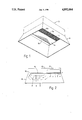
- FIG. 2 is a diagrammatic lateral cross-section of the heater.
- the heater shown is for mounting overhead e.g. near ceiling level of a room to be heated and comprises a box-like casing which will be supported or suspended by mountings (not shown).
- emitter panel 14 is formed from ceramic fibre though other materials as referred to above may be employed.
Landscapes
- Engineering & Computer Science (AREA)
- Chemical & Material Sciences (AREA)
- Combustion & Propulsion (AREA)
- Mechanical Engineering (AREA)
- General Engineering & Computer Science (AREA)
- Direct Air Heating By Heater Or Combustion Gas (AREA)
- Gas Burners (AREA)
Abstract
A radiant plaque heater adapted primarily for overhead use comprises the combination of a combustion panel, an emitter panel, and a combustion product flue wherein combustion products flow across the emitter panel in the direction of the flue and heat the latter to produce radiation which supplements that emitted by the combustion panel.
Description
This invention relates to space heating appliances of the kind in which a mix of fluid fuel, typically a gas fuel, and air is fed through a combustion panel, typically formed from a ceramic material, to burn at the face thereof so that radiant heat is emitted therefrom. Such appliances are hereinafter referred to as "radiant plaque heaters".
The object of the invention is to provide a radiant plaque heater which is particularly efficient and economical in operation, of simple construction, and reliable, safe and durable in use.
According to the invention there is provided a radiant plaque heater including at least one secondary emitter panel in close proximity to the combustion panel and formed of a heat resistant material, said secondary panel having no provision for feed of gas fuel/air mix thereto but at least some of the products of combustion and/or heated air from the front of the combustion panel flowing across the front face of the secondary panel so that heat therefrom is absorbed by and radiated from the latter panel to supplement the radiation from the combustion panel.
The heater may further incorporate one or more reflector formations for direction of the radiant heat emitted by the panels.
Preferably the panels are so arranged and/or the heater is so mounted in use that the secondary emitter panel or panels receive convective upward flow of combustion products and/or heated air from the combustion panel.
The acting front face area of the secondary panel or panels may be substantially equal to or somewhat greater than the acting front face area of the associated combustion panel or panels.
A variety of materials may be used for forming the secondary panels, preferably a lightweight non-degradable porous, fibrous or cellular material is used, e.g. a ceramic material. Among such materials, suitable for this application, are ceramic fibers, mineral wools, calcium silicate, amorphous silica, insulating firebrick, and/or porous ceramic tile.
An example of the invention is now more particularly described with reference to the accompanying drawings wherein:
FIG. 1 is a perspective view from below of an overhead radiant plaque heater, and
FIG. 2 is a diagrammatic lateral cross-section of the heater.
The heater shown is for mounting overhead e.g. near ceiling level of a room to be heated and comprises a box-like casing which will be supported or suspended by mountings (not shown).
A downwardly facing combustion panel 11, in this example made up of three ceramic tile plaques 11a arranged side by side, occupies somewhat less than one half of the downwardly directed area of casing 10. Panel 11 is operatively fed with a mix of gas fuel and air from a mixing chamber 12 above panel 11 in the known manner, combustion taking place at the exposed downwardly directed front faces of the plaque sections 11a so that radiant heat is emitted therefrom downwardly.
Immediately adjoining combustion panel 11 and occupying almost all the remaining downwardly directed area of casing 10 is a secondary emitter panel 14. The width of this panel is the same as or somewhat greater than the width of panel 11, preferably its exposed downwardly directed front area is at least equal to or up to one and a quarter times the exposed front face area of the combustion panel 11.
Along the side edge of panel 14 remote from the combustion panel is longitudinal gap forming a flue duct 16 extending upwardly within casing 10.
An upwardly tapering rectangular reflector 18 is secured to the lower edges of the side walls of casing 10 so that it surrounds both panels 11 and 14 to assist in directing radiant heat downwardly from the heater.
When mounted in its position of use the substantially co-planar downwardly directed acting faces of the panels 11 and 14 are preferably slightly inclined to the horizontal e.g. by about 5 degrees so that the flue duct 16 is above the level of the side of panel 11 remote therefrom.
As combustion takes place at the exposed face of panel 11 heated air and the hot products of combustion pass across the exposed lower face of the emitter panel 14 in their upward convection flow to reach duct 16 through which they exhaust from the heater. During this flow heat is transferred to and absorbed by panel 14 and is emitted therefrom as radiant heat supplementing the heating effect of the combustion panel 11. In this way substantially increased efficiency is obtained and wastage of heat is substantially reduced.
In this example emitter panel 14 is formed from ceramic fibre though other materials as referred to above may be employed.
Claims (10)
1. A radiant plaque heater comprising a casing, fluid fuel feeding means in said casing, combustion panel means in said casing and in communication with said fuel feeding means, said combustion panel means being adapted to receive fluid fuel therethrough for combustion at the face thereof and emission of radiant heat therefrom, combustion gas flue means in said casing and arranged to receive combustion products from said face of said combustion panel means and exhaust said products from said heater, and secondary emitter panel means in said casing between said combustion panel means and said flue means and presenting an exposed face which is in the path of flow of said products, whereby said exposed face is heated by said products resulting in radiant heat being emitted from said secondary panel means to supplement the radiant heat emitted from said combustion panel means.
2. The radiant plaque heater of claim 1 wherein said secondary emitter panel means is at least approximately in edge-to-edge relation with both said combustion panel means and said flue means, said secondary emitter panel means being resistant to combustion products flow therethrough.
3. The radiant plaque heater of claim 2 wherein said secondary emitter panel means is formed from a material selected from the group consisting of ceramic fibers, ceramic tile, mineral wools, calcium silicates, amorphous silica, and insulating firebrick.
4. The radiant plaque heater of claim 2 wherein said casing includes reflector means cooperating with said panel means in the direction of radiant heat emitted from said panel means.
5. The radiant plaque heater of claim 4 wherein said secondary emitter panel means is arranged in said casing relative to said combustion panel means so that said exposed face receives convective upward flow of said combustion products.
6. The radiant plaque heater of claim 5 wherein said exposed face of said secondary emitter panel means is of an area which is at least equal to the area of said face of said combustion panel means.
7. The radiant plaque heater of claim 1 wherein said casing includes reflector means cooperating with said panel means in the direction of radiant heat emitted from said panel means.
8. The radiant plaque heater of claim 1 wherein said exposed face of said secondary emitter panel means is of an area which is at least equal to the area of said face of said combustion panel means.
9. The radiant plaque heater of claim 8 wherein the area of said exposed face of said secondary emitter panel means is up to as much as one and one quarter greater than the area of said face of said combustion panel means.
10. The radiant plaque heater of claim 1 wherein said secondary emitter panel means is arranged in said casing relative to said combustion panel means so that said exposed face receives convective upward flow of said combustion products.
Applications Claiming Priority (2)
| Application Number | Priority Date | Filing Date | Title |
|---|---|---|---|
| GB8726277A GB2212257B (en) | 1987-11-10 | 1987-11-10 | Space heating appliance |
| GB8726277 | 1987-11-10 |
Publications (1)
| Publication Number | Publication Date |
|---|---|
| US4892084A true US4892084A (en) | 1990-01-09 |
Family
ID=10626707
Family Applications (1)
| Application Number | Title | Priority Date | Filing Date |
|---|---|---|---|
| US07/268,582 Expired - Fee Related US4892084A (en) | 1987-11-10 | 1988-11-08 | Space heating appliance |
Country Status (3)
| Country | Link |
|---|---|
| US (1) | US4892084A (en) |
| EP (1) | EP0316130A1 (en) |
| GB (1) | GB2212257B (en) |
Cited By (5)
| Publication number | Priority date | Publication date | Assignee | Title |
|---|---|---|---|---|
| US20040255927A1 (en) * | 2003-04-01 | 2004-12-23 | Johnson Roger N. | Radiant energy source systems, devices, and methods capturing, controlling, or recycling gas flows |
| US20060032490A1 (en) * | 2003-04-01 | 2006-02-16 | Johnson Roger N | Radiant energy source systems, devices, and methods capturing, controlling, or recycling gas flows |
| US20110079218A1 (en) * | 2009-09-25 | 2011-04-07 | Detroit Radiant Products Co. | Radiant heater |
| US20150345828A1 (en) * | 2014-05-29 | 2015-12-03 | David P. Clark | Patio heater with reflective shield |
| USD1018811S1 (en) * | 2022-08-12 | 2024-03-19 | Solo Brands, Llc | Heat reflector |
Families Citing this family (1)
| Publication number | Priority date | Publication date | Assignee | Title |
|---|---|---|---|---|
| GB2231949A (en) * | 1989-05-26 | 1990-11-28 | Burco Dean Appliances Ltd | Gas burner |
Citations (8)
| Publication number | Priority date | Publication date | Assignee | Title |
|---|---|---|---|---|
| GB790709A (en) * | 1954-11-08 | 1958-02-12 | Otto Heimerl | Improvements in heating devices utilising radiant heat |
| US3359965A (en) * | 1965-10-23 | 1967-12-26 | Milligan William Cecil | Radiant heaters |
| GB1488479A (en) * | 1974-10-03 | 1977-10-12 | United Gas Industries Ltd | Gas fire |
| GB1570246A (en) * | 1977-02-07 | 1980-06-25 | Pamplona Metalicas | Mobile domestic gas-burning heater |
| US4507083A (en) * | 1982-09-21 | 1985-03-26 | Joseph Fraioli | Gas-fired infrared projection heater |
| DE3415058A1 (en) * | 1984-04-21 | 1985-10-31 | GoGas Goch GmbH & Co, 4600 Dortmund | Radiant burner |
| GB2179438A (en) * | 1985-07-17 | 1987-03-04 | Flamelog And Coal Fires Limite | Solid-fuel simulating gas fire |
| GB2185100A (en) * | 1985-12-14 | 1987-07-08 | James Michael Wright | Simulated solid fuel gas fire |
-
1987
- 1987-11-10 GB GB8726277A patent/GB2212257B/en not_active Expired - Lifetime
-
1988
- 1988-11-08 US US07/268,582 patent/US4892084A/en not_active Expired - Fee Related
- 1988-11-08 EP EP88310474A patent/EP0316130A1/en not_active Ceased
Patent Citations (8)
| Publication number | Priority date | Publication date | Assignee | Title |
|---|---|---|---|---|
| GB790709A (en) * | 1954-11-08 | 1958-02-12 | Otto Heimerl | Improvements in heating devices utilising radiant heat |
| US3359965A (en) * | 1965-10-23 | 1967-12-26 | Milligan William Cecil | Radiant heaters |
| GB1488479A (en) * | 1974-10-03 | 1977-10-12 | United Gas Industries Ltd | Gas fire |
| GB1570246A (en) * | 1977-02-07 | 1980-06-25 | Pamplona Metalicas | Mobile domestic gas-burning heater |
| US4507083A (en) * | 1982-09-21 | 1985-03-26 | Joseph Fraioli | Gas-fired infrared projection heater |
| DE3415058A1 (en) * | 1984-04-21 | 1985-10-31 | GoGas Goch GmbH & Co, 4600 Dortmund | Radiant burner |
| GB2179438A (en) * | 1985-07-17 | 1987-03-04 | Flamelog And Coal Fires Limite | Solid-fuel simulating gas fire |
| GB2185100A (en) * | 1985-12-14 | 1987-07-08 | James Michael Wright | Simulated solid fuel gas fire |
Non-Patent Citations (1)
| Title |
|---|
| European Search Report No. EP 88 31 0474. * |
Cited By (8)
| Publication number | Priority date | Publication date | Assignee | Title |
|---|---|---|---|---|
| US20040255927A1 (en) * | 2003-04-01 | 2004-12-23 | Johnson Roger N. | Radiant energy source systems, devices, and methods capturing, controlling, or recycling gas flows |
| US6932079B2 (en) | 2003-04-01 | 2005-08-23 | Radiant Optics | Radiant energy source systems, devices, and methods capturing, controlling, or recycling gas flows |
| US20060032490A1 (en) * | 2003-04-01 | 2006-02-16 | Johnson Roger N | Radiant energy source systems, devices, and methods capturing, controlling, or recycling gas flows |
| US7116900B2 (en) | 2003-04-01 | 2006-10-03 | Radiant Optics, Inc. | Radiant energy source systems, devices, and methods capturing, controlling, or recycling gas flows |
| US20110079218A1 (en) * | 2009-09-25 | 2011-04-07 | Detroit Radiant Products Co. | Radiant heater |
| US8656904B2 (en) | 2009-09-25 | 2014-02-25 | Detroit Radiant Products Co. | Radiant heater |
| US20150345828A1 (en) * | 2014-05-29 | 2015-12-03 | David P. Clark | Patio heater with reflective shield |
| USD1018811S1 (en) * | 2022-08-12 | 2024-03-19 | Solo Brands, Llc | Heat reflector |
Also Published As
| Publication number | Publication date |
|---|---|
| GB8726277D0 (en) | 1987-12-16 |
| GB2212257B (en) | 1991-10-23 |
| GB2212257A (en) | 1989-07-19 |
| EP0316130A1 (en) | 1989-05-17 |
Similar Documents
| Publication | Publication Date | Title |
|---|---|---|
| US3805763A (en) | Flush-mountable, self-cooling gas-fired heater | |
| US5263471A (en) | Solid fuel clean burning zero clearance fireplace | |
| US5626125A (en) | Space heating appliances | |
| US2946510A (en) | High temperature conduit radiant overhead heating | |
| GB1117712A (en) | Improvements in or relating to fuel-fired heaters | |
| US2439038A (en) | Overhead gas-fired radiator and reflector | |
| US5054468A (en) | Unvented gas-fired fireplace heater | |
| US4892084A (en) | Space heating appliance | |
| GB2222673A (en) | Solid fuel effect gas fire | |
| WO1992008080A1 (en) | Combination of a baking oven and a stove | |
| EP0070360B1 (en) | A heating system | |
| US4676222A (en) | Radiant heaters | |
| CA2286040A1 (en) | Heaters | |
| GB2068106A (en) | Solid fuel effect gas fires | |
| GB2182431A (en) | Gas fire | |
| GB2213254A (en) | Gas-fired radiant burner | |
| US4654000A (en) | Infra-red generators and matrix therefor | |
| CN101432575A (en) | Heater for use in an agricultural house | |
| KR100201047B1 (en) | Pechika | |
| US3111122A (en) | Baseboard-type gas heater | |
| GB2274703A (en) | Space heating appliances | |
| US20240219033A1 (en) | Outdoor furnace table | |
| BRPI0621154A2 (en) | heating system and heating system in combination with a poultry farm | |
| US4337894A (en) | Wall protective heating system | |
| RU2082919C1 (en) | Room heater |
Legal Events
| Date | Code | Title | Description |
|---|---|---|---|
| FEPP | Fee payment procedure |
Free format text: PAYOR NUMBER ASSIGNED (ORIGINAL EVENT CODE: ASPN); ENTITY STATUS OF PATENT OWNER: SMALL ENTITY |
|
| AS | Assignment |
Owner name: AMBI-RAD LIMITED, P.O. BOX 30, ENFIELD WORKS, MUCK Free format text: ASSIGNMENT OF ASSIGNORS INTEREST.;ASSIGNOR:FLETCHER, JOHN E.;REEL/FRAME:004973/0242 Effective date: 19881104 |
|
| REMI | Maintenance fee reminder mailed | ||
| LAPS | Lapse for failure to pay maintenance fees | ||
| FP | Lapsed due to failure to pay maintenance fee |
Effective date: 19940109 |
|
| STCH | Information on status: patent discontinuation |
Free format text: PATENT EXPIRED DUE TO NONPAYMENT OF MAINTENANCE FEES UNDER 37 CFR 1.362 |