US488696A - Duplex arc lamp - Google Patents
Duplex arc lamp Download PDFInfo
- Publication number
- US488696A US488696A US488696DA US488696A US 488696 A US488696 A US 488696A US 488696D A US488696D A US 488696DA US 488696 A US488696 A US 488696A
- Authority
- US
- United States
- Prior art keywords
- lamp
- wire
- lever
- carbons
- coil
- Prior art date
- Legal status (The legal status is an assumption and is not a legal conclusion. Google has not performed a legal analysis and makes no representation as to the accuracy of the status listed.)
- Expired - Lifetime
Links
- OKTJSMMVPCPJKN-UHFFFAOYSA-N Carbon Chemical compound [C] OKTJSMMVPCPJKN-UHFFFAOYSA-N 0.000 description 9
- 229910052799 carbon Inorganic materials 0.000 description 9
- 238000010891 electric arc Methods 0.000 description 7
- 239000011435 rock Substances 0.000 description 6
- XEEYBQQBJWHFJM-UHFFFAOYSA-N Iron Chemical compound [Fe] XEEYBQQBJWHFJM-UHFFFAOYSA-N 0.000 description 4
- 229920001875 Ebonite Polymers 0.000 description 3
- 238000010276 construction Methods 0.000 description 3
- 229910001369 Brass Inorganic materials 0.000 description 2
- 239000010951 brass Substances 0.000 description 2
- 230000000881 depressing effect Effects 0.000 description 2
- 210000005069 ears Anatomy 0.000 description 2
- 229910052742 iron Inorganic materials 0.000 description 2
- 239000000463 material Substances 0.000 description 2
- 238000010586 diagram Methods 0.000 description 1
- 239000002184 metal Substances 0.000 description 1
- 229910052751 metal Inorganic materials 0.000 description 1
- 230000001105 regulatory effect Effects 0.000 description 1
- 239000002699 waste material Substances 0.000 description 1
Images


Classifications
-
- B—PERFORMING OPERATIONS; TRANSPORTING
- B23—MACHINE TOOLS; METAL-WORKING NOT OTHERWISE PROVIDED FOR
- B23K—SOLDERING OR UNSOLDERING; WELDING; CLADDING OR PLATING BY SOLDERING OR WELDING; CUTTING BY APPLYING HEAT LOCALLY, e.g. FLAME CUTTING; WORKING BY LASER BEAM
- B23K9/00—Arc welding or cutting
- B23K9/12—Automatic feeding or moving of electrodes or work for spot or seam welding or cutting
- B23K9/121—Devices for the automatic supply of at least two electrodes one after the other
Definitions
- My invention has a general relation to that class of electric arc lamps wherein two lamps are mounted side by side and known as double electric arc lamps, and in which the electric current is first utilized with the carbons of one lamp until they are consumed, and is then diverted to the carbons of the second lamp; and it has especial reference to improvements in devices and mechanism for transferring the current from the first to the second lamp when the carbons in the first shall have been exhausted, and from both lamps when the carbons of the second lamp are consumed.
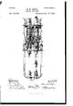
- Figure 1 is afront elevation of a double electric arc lamp, provided with my improvement;
- Fig. 2 a side elevation of the same, the lower part of the frame being omitted, and showing the position of the parts when the lamp is in operation;
- Fig. 3 a similar view of a part of the same in outline, showing the position of the parts after the carbons of the first are consumed, and
- Fig. 4 a diagram of the wire connections.
- 1, is a metallic frame on which is mounted aseries magnet 2, and below and in alignment with it a shunt magnet 3, the Wires of the formerbeinglarger than those of the latter, and the core of both being continuous and consisting of a brass tube 4, thereby constituting a'double wound solenoid with coils of different resistance. .In"
- the second lamp is identical in construction with the first, in which 9, is the series coil; 10, the shunt coil; 11, the central tube; 12, the tripping lever; 13, the suspending straps; 14, the clutch; and 15, the carbon-carrying rod.
- Attached to brackets on the lower plate of the frame 1, but electrically insulated therefrom is the pendent frame 16, bearing in its lower part the lower carbon clamps 17.
- a non conducting bracket 17 as of hard rubber, on which is mounted a metallic plate 18, having upright ears between which is pivoted a vertically rocking lever 19, of nonconducting material, as hard rubber,bearing on its outer end a metallic cap 20, arranged to come in contact with the plate 18, when rocked down, the inner end of said lever being constantly forced upward by a spring 21.
- the inner end of the lever 19, is extended laterally in each direction sufficiently to come below the outer ends of the tripping levers 5, 12; which ends of said levers are provided with adjustable screws 22, 23, arranged to engage the lateral extensions of the lever 19, when their inner ends are raised by the solenoids, thereby depressing the inner end of said lever 19, and breaking the contactbetween the cap 20, and plate 18.
- a metallic bracket 24 Clamped to one side of the frame 1, that supports the tripping lever 5, is a metallic bracket 24, provided with upright ears between which is pivoted a vertically rocking lever 25, of nonconducting material, as hard rubber, bearing at its inner end a metallic contact plate arranged, when said inder end is swung down to make contact with an inward projection of the bracket 24, and at the outer end a weight 26, by which it is constantly forced down.
- the outer end of this lever is arranged to be engaged and rocked upward by the outer end of the tripping lever 5, when the inner end of the latter is rocked down, as shown in Fig. 3, thereby bringing the inner end of thelever and bracket 24 in contact.
- the wire connections are as follows: The direct wire is connected with the insulated hook 27, and the return wire with the hook 28. From the lower end of the hook 27, a wire 29, passes direct to one end of the series coil 2, from the opposite end of which coil a wire passes to the collar through which the carbon rod 8, slides in the lower plate of the frame 1, thereby placing said carbon rod andlower plate in electrical connection with the direct wire. From the wire 29, a branch wire 31, extends across the front of the frame 1, under the upper plate in a resistance coil, mounted on an insulated block 32, to the cap 20, on the lever 19, with which it is connected. A second branch wire 33, extends from the wire 29, to and is connected with the bracket 24.
- the second lamp then commences to burn in the same manner as the first lamp until the carbons are consumed, when the inner'end of the lever 12, falls, releasing the lever 19, permitting the cap 20, and plate 18, to come in contact; when the current passes directly from the direct wire through the wires 31, 41, and 36, to the return wire, thereby cutting both lamps out of circuit.
- the series and shunt. coils, and the tripping levers arranged to be actuated by said coils, and the clamps and carbon-carrying rods, combined with a circuit closer interposed between the direct wire and the series coil of the second magnet, and arranged to be normally held open while the first lamp is burning, and to be closed by the carbon-carrying rod of the first lamp at the end of its descent, and a circuit closer interposed between the direct and return wires, normally closed and arranged to be held open by the tripping lever of each lamp while the same is burning, and provided with a resistance coil graduated to the resist ance of the arc between the carbons of each lamp, substantially as shown and for the purpose specified.
Landscapes
- Engineering & Computer Science (AREA)
- Physics & Mathematics (AREA)
- Plasma & Fusion (AREA)
- Mechanical Engineering (AREA)
- Breakers (AREA)
Description
mb M0661.) J 3 Sheets-Sheet 1.
H. M. ODELL.
DUPLEX ARG LAMP.
No. 488,696. Patented Dec. 27, 1892.
WW flmyM. Odell,-
(No Model.) I I 3.Sheets-Sheet 2'.
. M. ODELL. DUPLEX ARC LAMP.
No. 488,696. Patented Dec. 27,1892.
QM an i v Q (No Model.) 3 Sheets-Sheet 3.
H. M. ODELL DUPLEX ARG LAMP.
N0. 488,696. Patentd Dec. 27, 1892.
' lUNiTED STATES PATENT @EETCE.
HENRY M. ODELL, OF DETROIT, MICHIGAN.
DU PLEX ARC L'AM P.
SPECIFICATION forming part of Letters Patent N 0. 488,696, dated December 27, 1892. Application filed March 28,1892. SerialNo. 426,727. (No model.)
To all whom it may concern:
Be it known that I, HENRY M. ODELL, a citizen of the United States, residing at Detroit, in the county of Wayne and State of Michigan, have invented a certain new and useful Improvement in Duplex Electric-Arc Lamps, of which the following is a specification.
My invention has a general relation to that class of electric arc lamps wherein two lamps are mounted side by side and known as double electric arc lamps, and in which the electric current is first utilized with the carbons of one lamp until they are consumed, and is then diverted to the carbons of the second lamp; and it has especial reference to improvements in devices and mechanism for transferring the current from the first to the second lamp when the carbons in the first shall have been exhausted, and from both lamps when the carbons of the second lamp are consumed.
The objects of my invention are to provide new and improved devices whereby the current shall be automatically cut out of the first lamp when its carbons are consumed, and transferred to the carbons of the second lamp; to prevent interruption to the other lamps in the series during the interval of such transfer; and to out both lamps out of circuit and divert the current to the line wire of the series when the carbons of the second lamp are consumed.
To the aforesaid object my invention consists in the peculiar and novel construction, arrangement and combination of parts hereinafter described and then specifically pointed out in the claims, reference being had to the accompanying drawings, which form a part of this specification.
In the accompanying drawings, in which similar reference numerals indicate like parts in the different figures; Figure 1, is afront elevation of a double electric arc lamp, provided with my improvement; Fig. 2, a side elevation of the same, the lower part of the frame being omitted, and showing the position of the parts when the lamp is in operation; Fig. 3, a similar view of a part of the same in outline, showing the position of the parts after the carbons of the first are consumed, and Fig. 4, a diagram of the wire connections.
In the following description, the lamp at the right in Fig. l, andin front in Fig. 2, will for convenience be designated as the first lamp, and will be first described, the other lamp being called the second. As I do not claim to have invented these lamps, they will only be described with such particularity as to enable their general construction and mode of operation to be understood with a view of showing their connection with and relation to the shifting and cutting out device, which in itself and as connected with the operative parts of the lamps is the invention claimed in this specification.
Referring to the drawings, 1, is a metallic frame on which is mounted aseries magnet 2, and below and in alignment with it a shunt magnet 3, the Wires of the formerbeinglarger than those of the latter, and the core of both being continuous and consisting of a brass tube 4, thereby constituting a'double wound solenoid with coils of different resistance. .In"
the front of the tube 4, between the magnets 2, 3, is .a vertical slot through which is inserted the end of a tripping lever 5, pivotally mounted in the frame 1,and arranged to rock vertically, the end of which passing through the slot in the tube 4, enters a hole in a soft iron bar arranged to slide vertically in said tube and be moved therein by the variations in the power of said magnets 2, 3, in the usual manner of a free bar sliding in a solenoid. Pivotally connected with the lever 5, are two straps 6, which are connected with a clutch 7, arranged to grasp the carbon-carrying rod 8, and arrest its descent until released as hereinafter stated.
The second lamp is identical in construction with the first, in which 9, is the series coil; 10, the shunt coil; 11, the central tube; 12, the tripping lever; 13, the suspending straps; 14, the clutch; and 15, the carbon-carrying rod. Attached to brackets on the lower plate of the frame 1, but electrically insulated therefrom is the pendent frame 16, bearing in its lower part the lower carbon clamps 17. On the front upright of the frame 1, is a non conducting bracket 17, as of hard rubber, on which is mounted a metallic plate 18, having upright ears between which is pivoted a vertically rocking lever 19, of nonconducting material, as hard rubber,bearing on its outer end a metallic cap 20, arranged to come in contact with the plate 18, when rocked down, the inner end of said lever being constantly forced upward by a spring 21. The inner end of the lever 19, is extended laterally in each direction sufficiently to come below the outer ends of the tripping levers 5, 12; which ends of said levers are provided with adjustable screws 22, 23, arranged to engage the lateral extensions of the lever 19, when their inner ends are raised by the solenoids, thereby depressing the inner end of said lever 19, and breaking the contactbetween the cap 20, and plate 18.
Clamped to one side of the frame 1, that supports the tripping lever 5, is a metallic bracket 24, provided with upright ears between which is pivoted a vertically rocking lever 25, of nonconducting material, as hard rubber, bearing at its inner end a metallic contact plate arranged, when said inder end is swung down to make contact with an inward projection of the bracket 24, and at the outer end a weight 26, by which it is constantly forced down. The outer end of this lever is arranged to be engaged and rocked upward by the outer end of the tripping lever 5, when the inner end of the latter is rocked down, as shown in Fig. 3, thereby bringing the inner end of thelever and bracket 24 in contact. The wire connections are as follows: The direct wire is connected with the insulated hook 27, and the return wire with the hook 28. From the lower end of the hook 27, a wire 29, passes direct to one end of the series coil 2, from the opposite end of which coil a wire passes to the collar through which the carbon rod 8, slides in the lower plate of the frame 1, thereby placing said carbon rod andlower plate in electrical connection with the direct wire. From the wire 29, a branch wire 31, extends across the front of the frame 1, under the upper plate in a resistance coil, mounted on an insulated block 32, to the cap 20, on the lever 19, with which it is connected. A second branch wire 33, extends from the wire 29, to and is connected with the bracket 24. A third branch wire 34, extends from the wire 29, to one end of the shunt coil 3, from the opposite end of which a wire 35, runs to and is connected with a wire 36, that extends from the pendent frame 16, to the insulated hook 28. From the wire 35, a branch wire 37, runs to one end of the shunt coil 10. By this arrangement the upper plate of the frame 1, and the carbon-carrying rods 8, 15, are constantly in electrical connection with the direct wire, and the depending frame 16, and carbon clamps 17 in connection with the return wire. From the contact plate on the lever 25, a wire 38, connects with one end of the series coil 9, from which a branch wire 39, connects with the opposite end of the shunt coil 10, from that connected with the wire 37. From the opposite endof the series coil 9, a wire 40, connects with the collar through which the carbon rod 15, slides. A wire 41, connects the plate 18, with the wire 36.
In operation, carbons having been placed in the carbon rods 8, 15, and clamps 17, and the current having been turned on, the current passes through the series coil 2, to the collar of the carbon rod 8, thence through the carbons to the frame 16, and thence to the return wire. A portion of the current passes by the branch wire 34, to the shunt coil 3, and thence through the wire 35, to the return wire; thus both coils are energized, but while the carbons are in contact or slightly separated, the strength of the coil 2, overcomes that of the coil 3, and raises the soft metal bar in the brass tube 4, thereby rocking the inner end of the tripping lever upward and causing the clamp 7, to grasp and slightly raise the rod 8, thereby slightly separating the carbons and forming the are between their points. Simultaneously the outer end of the lever 25, being released, rocks down and separates the contact plate of the lever 25, and bracket 24, thereby breaking the connection between the wires 33, and 38. At the same time the end of the lever 19, is engaged and pressed down by the screw 22, breaking the connection between the wires 33, 38. The first lamp then continues to burn in the usual manner of such lamps; the series coil 2, losing a portion of its power as the carbons waste and permitting the shunt coil 3, to draw the iron bar down, rock the lever 5, release the clutch 7, and permit the carbon rod 8, to fall, untilas the points of the carbons approach, the current is again established through them and the series coil again energized,with the former result. This continues until the carbons of the first lamp are wasted so as to no longer approach sufficiently to permit the current to pass, when, the series coil 2, being no longer energized, the shunt coil 3, rocks the inner end of the lever 5, down as shown in Fig. 3. The lever 19, being released, the cap 20, rocks down and forms a contact with the plate 18, and closes the circuit through the wires 31, 41, so that the current passes directly from the direct wire to the return wire during the brief interval that elapses between the stopping of the first lamp and the commencement of the second, thereby preventing any interruption to the other lamps in the circuit during that interval, the resistance of the coil in the wire 31, being regulated to equal the resistance of the are between the carbons of the first lamp. As the carbon rod 8, falls, its head provided with an insulating annular disk, engages the contact plate of the lever 25; and rocks it down upon the bracket 2-1, thereby closing the connection between the wires 33 and 38. The current from the direct wire is thus carried directly to the series and shunt coils 9, 10,0f the second lamp; which being energized, operate in the same manner as the first lamp. As the inner end of the tripping lever 12, of the second lamp is raised, the screw 23, in its outer end engages the lateral extension of the lever 19, hereinbefore referred to, and depressing it again separates the plate 18, and cap 20, breaking the connection between thelevers 31,41. The second lamp then commences to burn in the same manner as the first lamp until the carbons are consumed, when the inner'end of the lever 12, falls, releasing the lever 19, permitting the cap 20, and plate 18, to come in contact; when the current passes directly from the direct wire through the wires 31, 41, and 36, to the return wire, thereby cutting both lamps out of circuit.
Having thus described my invention, What I claim and desire to secure by Letters Patent is:
1. In a double electric arc lamp the series and shunt coils, and the tripping lever arranged to be actuated by said coils, and the clutch and carbon-carrying rod, combined with a circuit closer interposed between the direct wireand series coil of the second lamp, and arranged to be normally held open while the first lamp is burning, and to be engaged by and closed by the carbon-carrying rod of the first lamp at the end of its descent, substantially as shown and described and for the purpose specified.
2. In a double electric arc lamp, the series and shunt coils and the tripping levers arranged to be actuated by said coils, and the clamps and carbon-carrying rods, combined with a circuit closer interposed between the direct and return wires, normally closed, and arranged to be held open by the tripping lever of each lamp while the same is burning, substantially as shown and described.
3. In a double electric arc lamp, the series and shunt. coils, and the tripping levers arranged to be actuated by said coils, and the clamps and carbon-carrying rods, combined with a circuit closer interposed between the direct wire and the series coil of the second magnet, and arranged to be normally held open while the first lamp is burning, and to be closed by the carbon-carrying rod of the first lamp at the end of its descent, and a circuit closer interposed between the direct and return wires, normally closed and arranged to be held open by the tripping lever of each lamp while the same is burning, and provided with a resistance coil graduated to the resist ance of the arc between the carbons of each lamp, substantially as shown and for the purpose specified.
In testimony that I claim the above I hereunto set my hand.
HENRY M. ODELL.
In presence of- (J. E. I-IUMPHREY, Gno. W. MERNMER.
Publications (1)
| Publication Number | Publication Date |
|---|---|
| US488696A true US488696A (en) | 1892-12-27 |
Family
ID=2557542
Family Applications (1)
| Application Number | Title | Priority Date | Filing Date |
|---|---|---|---|
| US488696D Expired - Lifetime US488696A (en) | Duplex arc lamp |
Country Status (1)
| Country | Link |
|---|---|
| US (1) | US488696A (en) |
-
0
- US US488696D patent/US488696A/en not_active Expired - Lifetime
Similar Documents
| Publication | Publication Date | Title |
|---|---|---|
| US418757A (en) | sgbibner | |
| US348927A (en) | pfannkuche | |
| US306225A (en) | Twelfths | |
| US531698A (en) | Charles a | |
| US299600A (en) | Ments | |
| US283482A (en) | Electric lamp | |
| US543900A (en) | Charles e | |
| US336503A (en) | House | |
| US463035A (en) | Electric-arc lamp | |
| US324008A (en) | Stone | |
| US515125A (en) | meissner | |
| US259007A (en) | guest | |
| US473955A (en) | Electric-arc lamp | |
| US301076A (en) | Edwaed weston | |
| US302061A (en) | Electric arc lamp | |
| US447767A (en) | Half to ii | |
| US376630A (en) | Electro-magnetic device | |
| US369456A (en) | Electric-arc lamp | |
| US559649A (en) | wheless | |
| US560387A (en) | bag-nall | |
| US480525A (en) | sperry | |
| US521798A (en) | Electric-arc lamp | |
| US338352A (en) | Geoege a | |
| US330450A (en) | Edwaed wteston | |
| US444154A (en) | Electric-arc lamp |