US4884778A - Attachment structure of a steering column - Google Patents
Attachment structure of a steering column Download PDFInfo
- Publication number
- US4884778A US4884778A US07/188,248 US18824888A US4884778A US 4884778 A US4884778 A US 4884778A US 18824888 A US18824888 A US 18824888A US 4884778 A US4884778 A US 4884778A
- Authority
- US
- United States
- Prior art keywords
- metallic
- resin
- bracket
- slider
- attachment structure
- Prior art date
- Legal status (The legal status is an assumption and is not a legal conclusion. Google has not performed a legal analysis and makes no representation as to the accuracy of the status listed.)
- Expired - Fee Related
Links
- 229920005989 resin Polymers 0.000 claims abstract description 52
- 239000011347 resin Substances 0.000 claims abstract description 52
- 239000002775 capsule Substances 0.000 abstract description 24
- 229910052751 metal Inorganic materials 0.000 description 5
- 239000002184 metal Substances 0.000 description 5
- XEEYBQQBJWHFJM-UHFFFAOYSA-N Iron Chemical compound [Fe] XEEYBQQBJWHFJM-UHFFFAOYSA-N 0.000 description 4
- 229910052782 aluminium Inorganic materials 0.000 description 3
- XAGFODPZIPBFFR-UHFFFAOYSA-N aluminium Chemical compound [Al] XAGFODPZIPBFFR-UHFFFAOYSA-N 0.000 description 3
- 229920003002 synthetic resin Polymers 0.000 description 3
- 239000000057 synthetic resin Substances 0.000 description 3
- 238000010276 construction Methods 0.000 description 2
- 230000008878 coupling Effects 0.000 description 2
- 238000010168 coupling process Methods 0.000 description 2
- 238000005859 coupling reaction Methods 0.000 description 2
- 230000000694 effects Effects 0.000 description 2
- 229910052742 iron Inorganic materials 0.000 description 2
- 230000002093 peripheral effect Effects 0.000 description 2
- 230000002040 relaxant effect Effects 0.000 description 2
- 238000000926 separation method Methods 0.000 description 1
Images


Classifications
-
- B—PERFORMING OPERATIONS; TRANSPORTING
- B62—LAND VEHICLES FOR TRAVELLING OTHERWISE THAN ON RAILS
- B62D—MOTOR VEHICLES; TRAILERS
- B62D1/00—Steering controls, i.e. means for initiating a change of direction of the vehicle
- B62D1/02—Steering controls, i.e. means for initiating a change of direction of the vehicle vehicle-mounted
- B62D1/16—Steering columns
- B62D1/18—Steering columns yieldable or adjustable, e.g. tiltable
- B62D1/19—Steering columns yieldable or adjustable, e.g. tiltable incorporating energy-absorbing arrangements, e.g. by being yieldable or collapsible
- B62D1/195—Yieldable supports for the steering column
-
- B—PERFORMING OPERATIONS; TRANSPORTING
- B62—LAND VEHICLES FOR TRAVELLING OTHERWISE THAN ON RAILS
- B62D—MOTOR VEHICLES; TRAILERS
- B62D1/00—Steering controls, i.e. means for initiating a change of direction of the vehicle
- B62D1/02—Steering controls, i.e. means for initiating a change of direction of the vehicle vehicle-mounted
- B62D1/16—Steering columns
-
- Y—GENERAL TAGGING OF NEW TECHNOLOGICAL DEVELOPMENTS; GENERAL TAGGING OF CROSS-SECTIONAL TECHNOLOGIES SPANNING OVER SEVERAL SECTIONS OF THE IPC; TECHNICAL SUBJECTS COVERED BY FORMER USPC CROSS-REFERENCE ART COLLECTIONS [XRACs] AND DIGESTS
- Y10—TECHNICAL SUBJECTS COVERED BY FORMER USPC
- Y10S—TECHNICAL SUBJECTS COVERED BY FORMER USPC CROSS-REFERENCE ART COLLECTIONS [XRACs] AND DIGESTS
- Y10S248/00—Supports
- Y10S248/90—Movable or disengageable on impact or overload
Definitions
- the present invention relates to an attachment structure of a steering column, and in particular, to an attachment structure of a steering column in which a steering jacket is detached from an attaching portion of a chassis at the colliding time of a vehicle, and is contracted in the axial direction of the steering shaft.
- a steering column for a vehicle is divided into upper and lower shafts, and is constructed to be contracted in the direction of the steering shaft when a driver hits his chest, etc., on the steering wheel and an impact force is applied to his chest at the colliding time, etc., thereby relaxing the impact force.
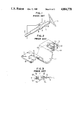
- FIG. 1 shows an attachment structure of a conventional steering column.
- a shaft column 2 is divided into upper and lower shafts within a jacket 1.
- the upper shaft compresses a buffer portion within the jacket 1, and is moved together with the jacket 1 in the direction of arrow A, thereby contracting the shaft column.
- the jacket 1 is supported by the bracket 3 fastened by a bolt 6 to a chassis 4.
- FIGS. 2 and 3 respectively show an enlarged perspective view and a cross-sectional view of the bracket 3 and a fastening portion thereof.
- a notch 8 is formed in a flange portion 7 of the bracket 3, and small holes 9 for receiving shear pins are disposed around the notch 8.
- a capsule 10 having an H shape in cross section is fitted into the notch 8, and has a bolt hole 11 in a central portion thereof.
- Small holes 13 for receiving shear pins are formed in a flange portion 12 of the capsule 10.
- Shear pins 14 made of synthetic resin are inserted and fixed into the small holes 9 and 13.
- the jacket 1 is fastened by bolts to the chassis 4 through the bracket 3 and the capsule 10, thereby completely fixing the jacket 1 to the chassis.
- the bracket 3 and the capsule 10 are fixed to each other through the shear pins 14 and the fitting frictional force therebetween. Accordingly, when a strong impact force in the direction of arrow A is applied to the steering wheel 5, the shear pins 14 are broken, and the bracket 3 is detached from the capsule 10 while holding the jacket 1, thereby contracting the shaft column 2 by a contracting mechanism within the jacket and relaxing the impact force.
- the pressing force from the steering wheel is normally applied in the horizontal direction, there causes a problem with respect to the frictional force between the upper face of the flange portion 7 of the bracket 3 and the lower face of the upper flange portion 12 of the capsule 10, in which the bracket 3 might not be detached from the capsule 10 at an emergency time since the frictional coefficient thereof is extremely high when they are made of metal such as iron, aluminum, etc.
- the occurrence of the collision of the vehicle is not limited on the front side thereof, but a slanting force is often applied to the vehicle.
- a secondary impact force from the steering wheel has a slanting direction, causing a problem with respect to the frictional force between side faces of the notch 8 and the capsule 10.
- an object of the present invention is to provide an attachment structure of a steering column for smoothly detaching a jacket from a capsule when an impact force is applied to the steering column, and reliably fixing the jacket to the capsule at the normal time.
- the present invention resides in an attachment structure of a steering column comprising bracket means fixed to a steering jacket for receiving a steering shaft and attaching the steering jacket to a chassis, said bracket means being attached to the chassis through metallic contact faces; and capsule means disposed in an attaching portion of the bracket means attached to the chassis and having metallic and resin sliders which overlap each other through the bracket means and attaches the bracket means to the chassis such that the bracket means is detachable from the metallic and resin sliders through metallic and resin contact faces.
- An attachment structure of a steering column may comprise bracket means for attaching steering means to base means for supporting the steering column; metallic and resin slider means fitted to each other to support the bracket means therebetween; means for preventing the relative movement between the resin slider means and the bracket means; and fastening means for attaching the bracket means to the base means through the metallic and resin slider means in a state in which the relative movement between the resin slider means and the bracket means is prevented.
- FIG. 1 is a side view of a conventional steering column
- FIG. 2 is a perspective view of an attachment structure of the conventional steering column of FIG. 1;
- FIG. 3 is a cross-sectional view of the attachment structure of FIG. 2;
- FIG. 4 is a perspective view of the whole construction of an attachment structure of a steering column in accordance with one embodiment of the present invention.
- FIG. 5 is a cross-sectional view of the attachment structure taken along line X--X of FIG. 4;
- FIG. 6 is a perspective view of the attachment structure when the structure is assembled
- FIG. 7 is a perspective view showing the whole construction of an attachment structure of a steering wheel in another embodiment of the present invention.
- FIG. 8 is a cross-sectional view of the attachment structure taken along line X--X of FIG. 7;
- FIG. 9 is a cross-sectional view of the attachment structure taken along line Y--Y of FIG. 7;
- FIG. 10A is a cross-sectional view corresponding to FIG. 8 showing the fastening state of a bolt
- FIG. 10B is a cross-sectional view corresponding to FIG. 9 showing the fastening state of the bolt.
- FIG. 11 is a cross-sectional view corresponding to FIG. 9 showing a state in which small projections are moved out of recessed portions.
- a trapezoidal notch 108 having a width gradually increasing on a steering wheel side is formed in a flange portion 107 of a bracket 103, and small notches 115 are disposed on both sides of the notch 108.
- a capsule 110 is divided into a metallic slider 116 and a resin slider 117.
- the metallic slider 116 has a projecting portion 118 in a central portion thereof, and the projecting portion 118 has a bolt hole 111 formed in a central portion thereof.
- a base portion 119 of the metallic slider 116 has a taper gradually thinner on the steering wheel side, and the projecting portion 118 has a taper gradually thicker on the steering wheel side.
- the upper face of the projecting portion 118 is substantially parallel to the bottom face of the base portion 119.
- the projecting portion 118 has the same planar shape as the trapezoidal shape of the notch 108.
- the contour of the resin slider 117 is the same as that of the base portion 119 of the metallic slider 116, and has a hole 120 disposed in a central portion thereof and receiving the projecting portion 118 of the metallic slider 116.
- the resin slider 117 further has small projections 121 on both sides of the hole 120.
- the projecting portion 118 of the metallic slider 116 is first inserted into the notch 108 from the lower side of the bracket 103, and the projecting portion 118 projecting upwards is fitted into the hole 120 of the resin slider 117.
- a peripheral portion of the notch 108 of the bracket 103 is held by the metallic slider 116 and the resin slider 117 therebetween, and the small projections 121 of the resin slider 117 are also fitted into the small notches 115 of the bracket 103.
- a bolt 106 is inserted into the bolt hole 120, and the bracket 103 is fastened to the chassis 104 by screwing a nut into the bolt 106.
- the bracket 103 When a secondary impact force is applied by collision, etc., to the structure from the steering wheel in the direction of arrow A, the bracket 103 is pressed in the direction of arrow A in FIG. 4, so that the small projections 121 made of resin are broken through the small notches 115 and the bracket 103 is moved out of the clearance between the metallic and resin sliders 116 and 117.
- the pressing force is applied to the structure in the horizontal direction, and the strongest frictional force is applied onto the upper face of the bracket 103 normally made of iron or aluminum and the lower face of the resin slider 117.
- the frictional coefficient of the resin and metal is low, and thereby the bracket 103 and the capsule 110 are easily detached from each other.
- the notch 108 has a trapezoidal shape, and the metallic and resin sliders 116 and 117 have tapers in the thickness direction thereof as shown in FIGS. 5 and 6 so that the bracket 103 and the capsule 110 are further easily detached from each other.
- the attachment structure of a steering column in accordance with the present invention has the following effects.
- bracket made of metal is fixed to a chassis through metallic faces, there is no creep in the structure and the structure is firmly constructed and safe.
- FIGS. 7 to 11 show another embodiment of the present invention.
- a trapezoidal notch 214 is disposed in each of flange portions 212 of a bracket 210 on both sides thereof, and the width of the notch 214 axially increases towards the steering wheel side.
- a metallic slider 216 is disposed on the lower side of the notch 214, and a resin slider 218 is disposed on the upper side of the notch 214.
- a peripheral portion of the notch 214 is supported by both sliders 216 and 218 therebetween.
- the metallic slider 216 is composed of a block made of aluminum, for example, and comprises a trapezoidal flange portion 220 having a size larger than that of the notch 214, a trapezoidal projecting portion 222 integrally projected from a central portion of the flange portion 220, and an elongated bolt hole 224 extending through the projecting portion 222 in the upward and downward directions.
- the resin slider 218 has the same trapezoidal shape as the flange portion 220, and a trapezoidal opening 226 disposed in a central portion thereof and fitted to the projecting portion 222.
- the resin slider 218 further has projecting portions 228 at the four upper corners thereof and slightly projected from the projecting portion 222 in a state in which the resin slider 218 is fitted onto the projecting portion 222 of the metallic slider 216 through the bracket 210.
- a pair of small projections 230 are formed on the lower faces of connecting portions between the projecting portions 228 on both sides thereof.
- the respective small projections 230 are disposed corresponding to recessed portions 232 formed on both sides of each of the notches 214 in the flange portions 212 of the bracket 210, and are fitted to the recessed portions 232 in a state in which both the sliders 216 and 218 are overlapped through the bracket 210.
- a bolt B is inserted into the bolt hole 224 in a state in which the flange portion 212 of the bracket 210 is supported by the sliders 216 and 218 therebetween, and is then screwed into a chassis 234.
- the respective projecting portions 228 make in contact with the chassis 234, and as shown in FIGS. 10A and 10B, the top surface of the projecting portion 222 of the metallic slider 216 makes in contact with the chassis 234 in a state in which the projections 228 are elastically deformed in the flat shape by the fastening force of the bolt B, thereby providing a firm coupling state by the contact between the metallic portions.
- the small projections 230 are fitted to the recessed portions 232.
- a predetermined clearance d 1 is formed between the chassis 234 and the connecting portions of the resin slider 218 except for the projecting portions 228 opposing the chassis 234.
- the clearance d 1 is set to be greater than fitted depth d 2 of the small projections 230.
- the central portion of the resin slider 218 is moved upwards and elastically deformed as shown in FIG. 11, so that the small projections 230 are moved out of the recessed portions 232.
- the lower face of the resin slider 218 mainly makes in frictional contact with the flange portion 212 most strongly.
- the frictional coefficient between the resin and the metal is low, and thereby the small projections 230 can be easily moved out of the recessed portions 232.
- the separation of the small projections 230 from the recessed portions 232 can be further facilitated by the trapezoidal shape of the notch 214.
- the attachment structure in accordance with this embodiment of the present invention has the following effects.
Landscapes
- Engineering & Computer Science (AREA)
- Chemical & Material Sciences (AREA)
- Combustion & Propulsion (AREA)
- Transportation (AREA)
- Mechanical Engineering (AREA)
- Steering Controls (AREA)
Abstract
Description
Claims (8)
Applications Claiming Priority (2)
| Application Number | Priority Date | Filing Date | Title |
|---|---|---|---|
| JP62-106926 | 1987-04-30 | ||
| JP62106926A JP2556510B2 (en) | 1987-04-30 | 1987-04-30 | Steering column mounting structure |
Publications (1)
| Publication Number | Publication Date |
|---|---|
| US4884778A true US4884778A (en) | 1989-12-05 |
Family
ID=14446017
Family Applications (1)
| Application Number | Title | Priority Date | Filing Date |
|---|---|---|---|
| US07/188,248 Expired - Fee Related US4884778A (en) | 1987-04-30 | 1988-04-29 | Attachment structure of a steering column |
Country Status (5)
| Country | Link |
|---|---|
| US (1) | US4884778A (en) |
| EP (1) | EP0289049B1 (en) |
| JP (1) | JP2556510B2 (en) |
| KR (1) | KR910004515B1 (en) |
| DE (1) | DE3877247T2 (en) |
Cited By (30)
| Publication number | Priority date | Publication date | Assignee | Title |
|---|---|---|---|---|
| DE4109162A1 (en) * | 1990-04-12 | 1991-10-17 | Savair Ltd | WELDING GUN DEVICE AND FLUID DRIVEN CYLINDER |
| DE4311665C1 (en) * | 1993-04-08 | 1994-08-18 | Metallgesellschaft Ag | Method for preparing alkali metal peroxide solutions |
| US5565116A (en) * | 1995-01-18 | 1996-10-15 | David D. Barton | Stud welding |
| US5673938A (en) * | 1996-05-13 | 1997-10-07 | Chrysler Corporation | Steering column quick-release mounting |
| US5704254A (en) * | 1995-02-13 | 1998-01-06 | Chrysler Corporation | Steering column isolator pads |
| US5819592A (en) * | 1997-01-17 | 1998-10-13 | Chrysler Corporation | Steering column support structure |
| US5979860A (en) * | 1998-04-16 | 1999-11-09 | Chrysler Corporation | Steering column support apparatus with shearable ribs |
| US6062100A (en) * | 1998-12-17 | 2000-05-16 | General Motors Corporation | Connection for energy absorbing steering column |
| US6176151B1 (en) * | 1999-05-06 | 2001-01-23 | Delphi Technologies, Inc. | Connection for energy absorbing steering column |
| US6431601B2 (en) * | 1999-12-24 | 2002-08-13 | Koyo Seiko Co., Ltd. | Electric power steering apparatus |
| US20040093976A1 (en) * | 2002-11-14 | 2004-05-20 | Burke Gerald F. | Collapsible steering column |
| US20050151362A1 (en) * | 2004-01-09 | 2005-07-14 | Mirjana Jurik | Steering column damping pad |
| US20050184500A1 (en) * | 2004-02-19 | 2005-08-25 | Delphi Technologies, Inc. | Snap on lower bracket and bearing support |
| US20050269812A1 (en) * | 2004-06-04 | 2005-12-08 | Nsk Ltd. | Steering column device |
| US20060157965A1 (en) * | 2005-01-18 | 2006-07-20 | Dubay Robert W | Snap-in capsule for steering columns |
| US20060226646A1 (en) * | 2005-03-31 | 2006-10-12 | Delphi Technologies Inc. | Release capsule for steering column |
| US20100019480A1 (en) * | 2008-07-28 | 2010-01-28 | Flaming River Industries, Inc. | Steering column attachment assembly |
| US20100300237A1 (en) * | 2009-05-29 | 2010-12-02 | Gm Global Technology Operations, Inc. | Collapsible Steering Column Assembly |
| US20110006509A1 (en) * | 2009-01-05 | 2011-01-13 | Gm Global Technology Operations Inc. | Steering Column Assembly Comprising A Mounting Capsule |
| US20110278426A1 (en) * | 2008-09-06 | 2011-11-17 | Patrick Anthony Duffy | Support Bracket for a Steering Column Assembly |
| US9174537B1 (en) | 2014-05-06 | 2015-11-03 | Ford Global Technologies, Llc | Fiber composite support for vehicular components |
| US9186993B1 (en) | 2014-05-06 | 2015-11-17 | Ford Global Technologies, Llc | Hybrid composite instrument panel |
| US9193394B1 (en) | 2014-05-06 | 2015-11-24 | Ford Global Technologies, Llc | Modular composite instrument panel |
| US9434095B2 (en) | 2014-05-06 | 2016-09-06 | Ford Global Technologies, Llc | Hybrid composite utilizing gas-assisted molding geometries |
| US9446540B2 (en) | 2014-05-06 | 2016-09-20 | Ford Global Technologies, Llc | Hybrid composite utilizing injection-expansion molding |
| US9688005B2 (en) | 2014-05-06 | 2017-06-27 | Ford Global Technologies, Llc | Method of making a hybrid composite instrument panel |
| US9988070B2 (en) * | 2014-02-27 | 2018-06-05 | Kyb Corporation | Steering device |
| RU2705877C2 (en) * | 2015-05-13 | 2019-11-12 | ФОРД ГЛОУБАЛ ТЕКНОЛОДЖИЗ, ЭлЭлСи | Vehicle instrument panel (embodiments) |
| RU2707597C2 (en) * | 2015-05-13 | 2019-11-28 | ФОРД ГЛОУБАЛ ТЕКНОЛОДЖИЗ, ЭлЭлСи | Vehicle instrument panel (embodiments) and vehicle component forming method |
| US11142239B2 (en) * | 2016-07-07 | 2021-10-12 | ZF Steering Systems Poland Sp. Z.o.o. | Steering column assembly |
Families Citing this family (9)
| Publication number | Priority date | Publication date | Assignee | Title |
|---|---|---|---|---|
| FR2699489B1 (en) * | 1992-12-17 | 1995-03-10 | Nacam | Motor vehicle steering column. |
| JP3264309B2 (en) * | 1995-05-12 | 2002-03-11 | 大豊工業株式会社 | Steering device coupling device |
| JP3393201B2 (en) * | 1995-05-12 | 2003-04-07 | 大豊工業株式会社 | Steering device coupling device |
| FR2737175B1 (en) * | 1995-07-26 | 1997-10-10 | Nacam | ENERGY ABSORPTION AND GUIDANCE DEVICE FOR AUTOMOTIVE VEHICLE STEERING COLUMN |
| ES2224639T3 (en) * | 1998-05-22 | 2005-03-01 | Thyssenkrupp Presta Ag | SECURITY SYSTEM IN CASE OF COLLISION FOR A STEERING COLUMN. |
| JP4543595B2 (en) * | 2001-08-09 | 2010-09-15 | 三菱自動車エンジニアリング株式会社 | Steering column mounting structure |
| US8955883B2 (en) * | 2011-11-07 | 2015-02-17 | Nsk Ltd. | Steering apparatus |
| CN105452088B (en) * | 2013-11-20 | 2017-09-22 | 日本精工株式会社 | The supporting arrangement and transfer of steering support |
| BE1031413B1 (en) * | 2023-03-08 | 2024-10-07 | Thyssenkrupp Presta Ag | Sliding element for a steering column of a motor vehicle and steering column for a motor vehicle |
Citations (15)
| Publication number | Priority date | Publication date | Assignee | Title |
|---|---|---|---|---|
| US2756795A (en) * | 1951-06-20 | 1956-07-31 | Gen Motors Corp | Resilient locking and sealing washer |
| US3394613A (en) * | 1966-09-28 | 1968-07-30 | Gen Motors Corp | Steering column mounting bracket assembly |
| US3415140A (en) * | 1967-04-03 | 1968-12-10 | Chrysler Corp | Sliding joint member and structure |
| US3476345A (en) * | 1968-03-15 | 1969-11-04 | Gen Motors Corp | Mounting arrangement for collapsible steering columns |
| FR2003996A6 (en) * | 1966-09-28 | 1969-11-14 | Gen Motors Corp | |
| GB1300284A (en) * | 1970-11-25 | 1972-12-20 | Accles & Pollock Ltd | Vehicle steering columns |
| US3707096A (en) * | 1971-03-05 | 1972-12-26 | Harry B Bennett | Steering column construction |
| GB1322234A (en) * | 1972-03-01 | 1973-07-04 | Ford Motor Co | Breakaway steering column support bracket |
| US3747427A (en) * | 1972-05-15 | 1973-07-24 | Gen Motors Corp | Mounting arrangement for collapsible steering column |
| US3813960A (en) * | 1972-12-26 | 1974-06-04 | Ford Motor Co | Energy absorbing steering column |
| US3868864A (en) * | 1973-09-17 | 1975-03-04 | Gen Motors Corp | Steering column mounting pad |
| DE2653377A1 (en) * | 1976-01-06 | 1977-07-14 | Cam Gears Ltd | ARRANGEMENT ON A SAFETY STEERING COLUMN |
| US4102217A (en) * | 1976-01-13 | 1978-07-25 | Nissan Motor Company, Ltd. | Support assembly of a collapsible steering column |
| US4194411A (en) * | 1977-04-06 | 1980-03-25 | Koyo Seiko Company Limited | Steering column support assembly |
| US4715756A (en) * | 1984-07-30 | 1987-12-29 | Trw Inc. | Nut and washer assembly |
Family Cites Families (1)
| Publication number | Priority date | Publication date | Assignee | Title |
|---|---|---|---|---|
| JPS5898269U (en) * | 1981-12-25 | 1983-07-04 | 大豊工業株式会社 | Energy-absorbing steering column support device |
-
1987
- 1987-04-30 JP JP62106926A patent/JP2556510B2/en not_active Expired - Fee Related
-
1988
- 1988-04-29 DE DE8888106919T patent/DE3877247T2/en not_active Expired - Fee Related
- 1988-04-29 KR KR1019880004933A patent/KR910004515B1/en not_active IP Right Cessation
- 1988-04-29 EP EP88106919A patent/EP0289049B1/en not_active Expired - Lifetime
- 1988-04-29 US US07/188,248 patent/US4884778A/en not_active Expired - Fee Related
Patent Citations (15)
| Publication number | Priority date | Publication date | Assignee | Title |
|---|---|---|---|---|
| US2756795A (en) * | 1951-06-20 | 1956-07-31 | Gen Motors Corp | Resilient locking and sealing washer |
| US3394613A (en) * | 1966-09-28 | 1968-07-30 | Gen Motors Corp | Steering column mounting bracket assembly |
| FR2003996A6 (en) * | 1966-09-28 | 1969-11-14 | Gen Motors Corp | |
| US3415140A (en) * | 1967-04-03 | 1968-12-10 | Chrysler Corp | Sliding joint member and structure |
| US3476345A (en) * | 1968-03-15 | 1969-11-04 | Gen Motors Corp | Mounting arrangement for collapsible steering columns |
| GB1300284A (en) * | 1970-11-25 | 1972-12-20 | Accles & Pollock Ltd | Vehicle steering columns |
| US3707096A (en) * | 1971-03-05 | 1972-12-26 | Harry B Bennett | Steering column construction |
| GB1322234A (en) * | 1972-03-01 | 1973-07-04 | Ford Motor Co | Breakaway steering column support bracket |
| US3747427A (en) * | 1972-05-15 | 1973-07-24 | Gen Motors Corp | Mounting arrangement for collapsible steering column |
| US3813960A (en) * | 1972-12-26 | 1974-06-04 | Ford Motor Co | Energy absorbing steering column |
| US3868864A (en) * | 1973-09-17 | 1975-03-04 | Gen Motors Corp | Steering column mounting pad |
| DE2653377A1 (en) * | 1976-01-06 | 1977-07-14 | Cam Gears Ltd | ARRANGEMENT ON A SAFETY STEERING COLUMN |
| US4102217A (en) * | 1976-01-13 | 1978-07-25 | Nissan Motor Company, Ltd. | Support assembly of a collapsible steering column |
| US4194411A (en) * | 1977-04-06 | 1980-03-25 | Koyo Seiko Company Limited | Steering column support assembly |
| US4715756A (en) * | 1984-07-30 | 1987-12-29 | Trw Inc. | Nut and washer assembly |
Cited By (41)
| Publication number | Priority date | Publication date | Assignee | Title |
|---|---|---|---|---|
| DE4109162A1 (en) * | 1990-04-12 | 1991-10-17 | Savair Ltd | WELDING GUN DEVICE AND FLUID DRIVEN CYLINDER |
| DE4311665C1 (en) * | 1993-04-08 | 1994-08-18 | Metallgesellschaft Ag | Method for preparing alkali metal peroxide solutions |
| US5565116A (en) * | 1995-01-18 | 1996-10-15 | David D. Barton | Stud welding |
| US5704254A (en) * | 1995-02-13 | 1998-01-06 | Chrysler Corporation | Steering column isolator pads |
| US5673938A (en) * | 1996-05-13 | 1997-10-07 | Chrysler Corporation | Steering column quick-release mounting |
| US5819592A (en) * | 1997-01-17 | 1998-10-13 | Chrysler Corporation | Steering column support structure |
| US5979860A (en) * | 1998-04-16 | 1999-11-09 | Chrysler Corporation | Steering column support apparatus with shearable ribs |
| US6062100A (en) * | 1998-12-17 | 2000-05-16 | General Motors Corporation | Connection for energy absorbing steering column |
| US6176151B1 (en) * | 1999-05-06 | 2001-01-23 | Delphi Technologies, Inc. | Connection for energy absorbing steering column |
| US6431601B2 (en) * | 1999-12-24 | 2002-08-13 | Koyo Seiko Co., Ltd. | Electric power steering apparatus |
| US20040093976A1 (en) * | 2002-11-14 | 2004-05-20 | Burke Gerald F. | Collapsible steering column |
| US20050151362A1 (en) * | 2004-01-09 | 2005-07-14 | Mirjana Jurik | Steering column damping pad |
| US20050184500A1 (en) * | 2004-02-19 | 2005-08-25 | Delphi Technologies, Inc. | Snap on lower bracket and bearing support |
| US7469615B2 (en) | 2004-02-19 | 2008-12-30 | Delphi Technologies, Inc. | Snap on lower bracket and bearing support |
| US20050269812A1 (en) * | 2004-06-04 | 2005-12-08 | Nsk Ltd. | Steering column device |
| US7367588B2 (en) | 2004-06-04 | 2008-05-06 | Nsk Ltd. | Steering column device |
| US20060157965A1 (en) * | 2005-01-18 | 2006-07-20 | Dubay Robert W | Snap-in capsule for steering columns |
| US7229097B2 (en) | 2005-01-18 | 2007-06-12 | Delphi Technologies, Inc. | Snap-in capsule for steering columns |
| US20060226646A1 (en) * | 2005-03-31 | 2006-10-12 | Delphi Technologies Inc. | Release capsule for steering column |
| US7228755B2 (en) * | 2005-03-31 | 2007-06-12 | Delphi Technologies, Inc. | Release capsule for steering column |
| US20100019480A1 (en) * | 2008-07-28 | 2010-01-28 | Flaming River Industries, Inc. | Steering column attachment assembly |
| US7976065B2 (en) * | 2008-07-28 | 2011-07-12 | Flaming River Industries, Inc. | Steering column attachment assembly |
| US20110278426A1 (en) * | 2008-09-06 | 2011-11-17 | Patrick Anthony Duffy | Support Bracket for a Steering Column Assembly |
| US8678436B2 (en) * | 2008-09-06 | 2014-03-25 | Trw Automotive Us Llc | Support bracket for a steering column assembly |
| US20110006509A1 (en) * | 2009-01-05 | 2011-01-13 | Gm Global Technology Operations Inc. | Steering Column Assembly Comprising A Mounting Capsule |
| US8430428B2 (en) | 2009-01-05 | 2013-04-30 | Steering Solutions Ip Holding Corporation | Steering column assembly comprising a mounting capsule |
| US20100300237A1 (en) * | 2009-05-29 | 2010-12-02 | Gm Global Technology Operations, Inc. | Collapsible Steering Column Assembly |
| US8979128B2 (en) * | 2009-05-29 | 2015-03-17 | Steering Solutions Ip Holding Corporation | Collapsible steering column assembly |
| US9988070B2 (en) * | 2014-02-27 | 2018-06-05 | Kyb Corporation | Steering device |
| US9434095B2 (en) | 2014-05-06 | 2016-09-06 | Ford Global Technologies, Llc | Hybrid composite utilizing gas-assisted molding geometries |
| US9193394B1 (en) | 2014-05-06 | 2015-11-24 | Ford Global Technologies, Llc | Modular composite instrument panel |
| US9186993B1 (en) | 2014-05-06 | 2015-11-17 | Ford Global Technologies, Llc | Hybrid composite instrument panel |
| US9446540B2 (en) | 2014-05-06 | 2016-09-20 | Ford Global Technologies, Llc | Hybrid composite utilizing injection-expansion molding |
| US9682729B2 (en) | 2014-05-06 | 2017-06-20 | Ford Global Technologies, Llc | Fiber composite support for vehicular components |
| US9682731B2 (en) | 2014-05-06 | 2017-06-20 | Ford Global Technologies, Llc | Vehicular composite instrument panel and component |
| US9688005B2 (en) | 2014-05-06 | 2017-06-27 | Ford Global Technologies, Llc | Method of making a hybrid composite instrument panel |
| US9950749B2 (en) | 2014-05-06 | 2018-04-24 | Ford Global Technologies, Llc | Hybrid composite instrument panel |
| US9174537B1 (en) | 2014-05-06 | 2015-11-03 | Ford Global Technologies, Llc | Fiber composite support for vehicular components |
| RU2705877C2 (en) * | 2015-05-13 | 2019-11-12 | ФОРД ГЛОУБАЛ ТЕКНОЛОДЖИЗ, ЭлЭлСи | Vehicle instrument panel (embodiments) |
| RU2707597C2 (en) * | 2015-05-13 | 2019-11-28 | ФОРД ГЛОУБАЛ ТЕКНОЛОДЖИЗ, ЭлЭлСи | Vehicle instrument panel (embodiments) and vehicle component forming method |
| US11142239B2 (en) * | 2016-07-07 | 2021-10-12 | ZF Steering Systems Poland Sp. Z.o.o. | Steering column assembly |
Also Published As
| Publication number | Publication date |
|---|---|
| EP0289049B1 (en) | 1993-01-07 |
| EP0289049A2 (en) | 1988-11-02 |
| DE3877247T2 (en) | 1993-04-29 |
| EP0289049A3 (en) | 1989-05-31 |
| KR880012421A (en) | 1988-11-26 |
| KR910004515B1 (en) | 1991-07-05 |
| DE3877247D1 (en) | 1993-02-18 |
| JP2556510B2 (en) | 1996-11-20 |
| JPS63270280A (en) | 1988-11-08 |
Similar Documents
| Publication | Publication Date | Title |
|---|---|---|
| US4884778A (en) | Attachment structure of a steering column | |
| US4786119A (en) | Locking clip for securing a bolt holding panel members together | |
| US5823495A (en) | Mounting apparatus for a high power mobile radio | |
| US3957127A (en) | Motor vehicle structure including a resilient mount | |
| US7393014B2 (en) | Energy absorbing support for a vehicle steering assembly | |
| US6033145A (en) | Steering wheel attachment apparatus | |
| US6357811B1 (en) | Coupling structure of threaded member and synthetic resin part for vehicle | |
| JPH01278877A (en) | Setting structure for steering column | |
| JPS634678Y2 (en) | ||
| KR0130450Y1 (en) | Screw clip for fitting bumper cover | |
| JPH0244423Y2 (en) | ||
| CN215333878U (en) | Bolt fastening structure | |
| JPH06179337A (en) | Cap for rail of seat slide | |
| JPS6318255Y2 (en) | ||
| JPH0642923Y2 (en) | Steering wheel | |
| JP3237335B2 (en) | Automotive bumper stay device | |
| JP3327163B2 (en) | Steering wheel | |
| JPH0626727Y2 (en) | Member structure for vehicle | |
| JPH0323886Y2 (en) | ||
| JPS6343031Y2 (en) | ||
| JPH0522462Y2 (en) | ||
| JP2517984Y2 (en) | Wheel cover mounting structure | |
| JP2754985B2 (en) | Bolt structure | |
| JP2512912Y2 (en) | Steering wheel | |
| JP2545192Y2 (en) | Horn pad mounting structure to steering wheel |
Legal Events
| Date | Code | Title | Description |
|---|---|---|---|
| AS | Assignment |
Owner name: FUJIKIKO KABUSHIKI KAISHA, 1-13 NIHOMBASHIHONCHO, Free format text: ASSIGNMENT OF ASSIGNORS INTEREST.;ASSIGNOR:YAMAMOTO, YOSHIMI;REEL/FRAME:004950/0217 Effective date: 19880525 Owner name: FUJIKIKO KABUSHIKI KAISHA, 1-13 NIHOMBASHIHONCHO, Free format text: ASSIGNMENT OF ASSIGNORS INTEREST;ASSIGNOR:YAMAMOTO, YOSHIMI;REEL/FRAME:004950/0217 Effective date: 19880525 |
|
| FEPP | Fee payment procedure |
Free format text: PAYOR NUMBER ASSIGNED (ORIGINAL EVENT CODE: ASPN); ENTITY STATUS OF PATENT OWNER: LARGE ENTITY |
|
| FPAY | Fee payment |
Year of fee payment: 4 |
|
| FPAY | Fee payment |
Year of fee payment: 8 |
|
| REMI | Maintenance fee reminder mailed | ||
| LAPS | Lapse for failure to pay maintenance fees | ||
| STCH | Information on status: patent discontinuation |
Free format text: PATENT EXPIRED DUE TO NONPAYMENT OF MAINTENANCE FEES UNDER 37 CFR 1.362 |
|
| FP | Lapsed due to failure to pay maintenance fee |
Effective date: 20011205 |