US4884015A - Probing control method and apparatus for mechanism with multiple degrees of freedom - Google Patents

Probing control method and apparatus for mechanism with multiple degrees of freedom Download PDF

Info

Publication number
US4884015A
US4884015A US06/875,189 US87518986A US4884015A US 4884015 A US4884015 A US 4884015A US 87518986 A US87518986 A US 87518986A US 4884015 A US4884015 A US 4884015A
Authority
US
United States
Prior art keywords
actuators
movement
driving
output
frame
Prior art date
Legal status (The legal status is an assumption and is not a legal conclusion. Google has not performed a legal analysis and makes no representation as to the accuracy of the status listed.)
Expired - Fee Related
Application number
US06/875,189
Inventor
Koichi Sugimoto
Hisaaki Hirabayashi
Tomoyuki Masui
Current Assignee (The listed assignees may be inaccurate. Google has not performed a legal analysis and makes no representation or warranty as to the accuracy of the list.)
Hitachi Ltd
Original Assignee
Hitachi Ltd
Priority date (The priority date is an assumption and is not a legal conclusion. Google has not performed a legal analysis and makes no representation as to the accuracy of the date listed.)
Filing date
Publication date
Priority claimed from JP60129806A external-priority patent/JPH0652488B2/en
Priority claimed from JP21501485A external-priority patent/JPS6275508A/en
Application filed by Hitachi Ltd filed Critical Hitachi Ltd
Assigned to HITACHI, LTD. reassignment HITACHI, LTD. ASSIGNMENT OF ASSIGNORS INTEREST. Assignors: HIRABAYASHI, HISAAKI, MASUI, TOMOYUKI, SUGIMOTO, KOICHI
Application granted granted Critical
Publication of US4884015A publication Critical patent/US4884015A/en
Anticipated expiration legal-status Critical
Expired - Fee Related legal-status Critical Current

Links

Images

Classifications

    • BPERFORMING OPERATIONS; TRANSPORTING
    • B23MACHINE TOOLS; METAL-WORKING NOT OTHERWISE PROVIDED FOR
    • B23QDETAILS, COMPONENTS, OR ACCESSORIES FOR MACHINE TOOLS, e.g. ARRANGEMENTS FOR COPYING OR CONTROLLING; MACHINE TOOLS IN GENERAL CHARACTERISED BY THE CONSTRUCTION OF PARTICULAR DETAILS OR COMPONENTS; COMBINATIONS OR ASSOCIATIONS OF METAL-WORKING MACHINES, NOT DIRECTED TO A PARTICULAR RESULT
    • B23Q1/00Members which are comprised in the general build-up of a form of machine, particularly relatively large fixed members
    • B23Q1/25Movable or adjustable work or tool supports
    • B23Q1/26Movable or adjustable work or tool supports characterised by constructional features relating to the co-operation of relatively movable members; Means for preventing relative movement of such members
    • B23Q1/34Relative movement obtained by use of deformable elements, e.g. piezoelectric, magnetostrictive, elastic or thermally-dilatable elements
    • B23Q1/36Springs
    • BPERFORMING OPERATIONS; TRANSPORTING
    • B23MACHINE TOOLS; METAL-WORKING NOT OTHERWISE PROVIDED FOR
    • B23QDETAILS, COMPONENTS, OR ACCESSORIES FOR MACHINE TOOLS, e.g. ARRANGEMENTS FOR COPYING OR CONTROLLING; MACHINE TOOLS IN GENERAL CHARACTERISED BY THE CONSTRUCTION OF PARTICULAR DETAILS OR COMPONENTS; COMBINATIONS OR ASSOCIATIONS OF METAL-WORKING MACHINES, NOT DIRECTED TO A PARTICULAR RESULT
    • B23Q15/00Automatic control or regulation of feed movement, cutting velocity or position of tool or work
    • B23Q15/20Automatic control or regulation of feed movement, cutting velocity or position of tool or work before or after the tool acts upon the workpiece
    • B23Q15/22Control or regulation of position of tool or workpiece
    • B23Q15/24Control or regulation of position of tool or workpiece of linear position
    • GPHYSICS
    • G02OPTICS
    • G02BOPTICAL ELEMENTS, SYSTEMS OR APPARATUS
    • G02B6/00Light guides; Structural details of arrangements comprising light guides and other optical elements, e.g. couplings
    • G02B6/24Coupling light guides
    • G02B6/36Mechanical coupling means
    • G02B6/38Mechanical coupling means having fibre to fibre mating means
    • G02B6/3801Permanent connections, i.e. wherein fibres are kept aligned by mechanical means
    • G02B6/3803Adjustment or alignment devices for alignment prior to splicing
    • GPHYSICS
    • G02OPTICS
    • G02BOPTICAL ELEMENTS, SYSTEMS OR APPARATUS
    • G02B6/00Light guides; Structural details of arrangements comprising light guides and other optical elements, e.g. couplings
    • G02B6/24Coupling light guides
    • G02B6/42Coupling light guides with opto-electronic elements
    • G02B6/4201Packages, e.g. shape, construction, internal or external details
    • G02B6/4219Mechanical fixtures for holding or positioning the elements relative to each other in the couplings; Alignment methods for the elements, e.g. measuring or observing methods especially used therefor
    • G02B6/422Active alignment, i.e. moving the elements in response to the detected degree of coupling or position of the elements
    • G02B6/4226Positioning means for moving the elements into alignment, e.g. alignment screws, deformation of the mount
    • GPHYSICS
    • G02OPTICS
    • G02BOPTICAL ELEMENTS, SYSTEMS OR APPARATUS
    • G02B6/00Light guides; Structural details of arrangements comprising light guides and other optical elements, e.g. couplings
    • G02B6/24Coupling light guides
    • G02B6/42Coupling light guides with opto-electronic elements
    • G02B6/4201Packages, e.g. shape, construction, internal or external details
    • G02B6/4219Mechanical fixtures for holding or positioning the elements relative to each other in the couplings; Alignment methods for the elements, e.g. measuring or observing methods especially used therefor
    • G02B6/422Active alignment, i.e. moving the elements in response to the detected degree of coupling or position of the elements
    • G02B6/4227Active alignment methods, e.g. procedures and algorithms

Definitions

  • the present invention relates to a controlling method and apparatus for a mechanism with multiple degrees of freedom which is used in an automatic adjustment operation. More particularly, the invention is concerned with a probing control method and apparatus suitable for driving an object in such a manner that an estimation function determined from the output of the object takes the maximum value. Still more particularly, the invention is concerned with an adjusting method and apparatus suitable for use in attaining alignment of optical axes in laser diodes with optical fibers.
  • a laser diode with optical fiber is shown in IEEE JOURNAL OF QUANTUM ELECTRONICS, VOL. QE-16, No. 10, OCTOBER 1986, pp 1059-1066, "Design of a Miniature Lens for Semiconductor Laser to Single-Mode Fiber Coupling".
  • the optical axis alignment is attained by moving the optical fiber uniaxially, i.e., with one-degree of freedom, and fixing the optical fiber at a point where the output from the fiber is maximized.
  • the movement of the optical fiber in one-degree of freedom it is not possible to attain the true maximum output point due to, for example, lack of precision of parts, with a result that the optical axis alignment cannot be conducted with sufficiently high precision.
  • an object of the invention is to provide a probing control method which incorporates a mechanism with multiple degrees of freedom so as to move an object such as an optical fiber three-dimensionally, thereby to find out the point where the level of the output from the object is maximized.
  • Another object of the invention is to provide a method of controlling an automatic aligning device for optical axis alignment of a laser diode with optical fiber, capable of attaining the optical axis alignment of the fiber through detection of a point where the optical output value from the fiber is maximized.
  • Still another object of the invention is to provide a probing control method which is capable of diminishing the probing time and the load applied to the mechanism.
  • a method of driving in one-by-one fashion and in accordance with a predetermined sequence, n pieces of actuators for actuating a mechanism with n-degrees of freedom, the method comprising detecting the amount of change in the output from a control object in response to the operation of said actuators, forming a command for each actuator from driving data containing the amount of movement of said actuator in the preceding operation and the amount of change in the output from the control object, and driving each actuator in accordance with the thus formed command.
  • FIG. 1 is a sectional view of a laser diode with an optical fiber
  • FIG. 2 is an illustration of the construction of a supporting column shown in FIG. 1;
  • FIG. 3 is an illustration of a fine adjustment mechanism employed in the method of the invention.
  • FIG. 4 is a block diagram of the whole construction of an optical axis aligning apparatus to which the invention is applied;
  • FIGS. 5a and 5b are charts showing the result of the control
  • FIG. 6 is a flow chart illustrating the controlling procedure in accordance with a first embodiment of the probing control method in accordance with the invention.
  • FIG. 7 is a flow chart illustrating the control procedure in accordance with a second embodiment.
  • FIG. 1 shows an example of the construction of a laser diode.
  • a reference numeral 1 denotes a laser diode chip fixed to a sub-mount 2 which is in turn secured to a frame 3.
  • an optical fiber 4 passes through a hole formed in the central portion of a supporting post 5 which is fixed at its one end to frame 3. The output end is led to the outside through a hole formed in the frame 3.
  • the position of the light-emitting portion of the laser diode chip 1 fluctuates with respect to the frame 3, due to insufficient precision of machining of the chip and insufficient precision of mounting the chip on the sub-mount.
  • the position of the end of the optical fiber fluctuates.
  • the optical axes of the laser diode chip 1 and the optical fiber 4 are aligned with a precision in the order of 0.1 ⁇ m to 1 ⁇ m.
  • the alignment has been attained by grasping one end of the supporting post 5, moving the supporting post 5 in the X and Y directions or X, Y and ⁇ directions, thereby moving the end of the optical fiber 4 while plastically deforming the supporting post 5.
  • the output from the optical fiber 4 is observed to probe the position where the output value exceeds a predetermined level, thereby attaining optical axis alignment between the optical fiber 4 and the laser diode chip 1.
  • FIG. 3 shows a mechanism having three degrees of freedom, as an example of the mechanism with multiple degrees of freedom.
  • This mechanism 6 has a fine adjustment device composed of an outer frame 7, intermediate frame 8, inner frame 9 and an end frame 10.
  • the outer frame 7 and the intermediate frame 8 are coupled to each other through a parallel leaf spring mechanism.
  • the intermediate frame 8 and the inner frame 9 are coupled to each other through a similar parallel leaf spring mechanism.
  • the outer frame 7 and the intermediate frame 8; and the inner frame 8 and the intermediate frame 9 are adapted to be displaced in X and Y directions by piezoelectric actuators 11 and 12, in proportion to the voltage applied to piezoelectric actuators.
  • the inner frame 9 and the end frame 10 are coupled through a spring mechanism which is constructed in such a manner as to cross at the central points, and are adapted to be actuated by a piezoelectric actuator 13, thereby effecting minute angular movement about the central point (in the ⁇ direction) proportional to the voltage applied to the piezoelectric actuator.
  • a supporting post gripper is fixed to the lower side (not shown) of the end frame 10. The gripper can grip the supporting post 5 so as to deflect the latter in three directions, i.e., X, Y and ⁇ directions.
  • the outer frame 7 is fixed to a stationary member.
  • FIG. 4 shows the arrangement of the whole portion of the invention.
  • the output from the laser diode 1 is detected by a detector 14 and is sent to a controller 15.
  • the controller 15 computes the amounts of driving of three piezoelectric actuators in accordance with the following method, and applies to each piezoelectric actuator a voltage corresponding to the computed value.
  • the optical output f detected by the detector 14 through the fiber is determined by x, y and ⁇ .
  • a movement by amount ⁇ x 1 is caused and the gradient of the optical power distribution surface is determined by the difference in the optical output between the state before the movement and the state after the movement.
  • f 0 and f x1 represent the value of the optical output in the states before and after the movement by the amount ⁇ x 1 .
  • a movement by the amount ⁇ y 1 is effected to provide the following condition.
  • f x1 and f y1 represent the optical output values obtained in the states before and after the movement by the amount ⁇ y 1 and can be determined by measurement.
  • a movement by the amount ⁇ 1 is conducted so that the following condition is obtained. ##EQU3##
  • A, B, j and k are constants the optimum values of which are obtainable through experiments. If the constant A is positive, the movement is caused in such a direction as to reduce s, whereas, when the constant A is negative, the movement is caused in such a direction as to decrease the value s. It is to be noted also that the amount of movement is decreased as the value h is increased.
  • the cycles of movement are further repeated until the number n exceeds a predetermined value or the value s comes down below a predetermined value or the value h exceeds a predetermined value.
  • the movement in respective steps for the purpose of the probing is intended not only for the approach to the designated maximum value but also for the measurement of the gradient in the vicinity of the maximum value point.
  • an efficient probing is executed because the probing and the measurement of gradient are conducted at one time.
  • the movement by the amount ⁇ x in the x-axis direction is followed by the movement in the - ⁇ x direction, and a subsequent movement ⁇ y in the y-axis direction is followed by a movement - ⁇ y , and finally a movement is effected in the steepest direction on the x, y plane.
  • the method of the invention is superior to the above-explained severest method in that (1) the number of the moving cycles is smaller, and that (2) number of sharp turns (movement - ⁇ x following the movement ⁇ x means 180° change in the moving direction) is smaller.
  • Step 104 a movement ⁇ x 10 is caused in the direction x 1 .
  • the amount of change in the optical output is expressed by ⁇ f.
  • the gradient of the optical power distribution surface shown by the far field pattern in the direction x 1 is expressed as ⁇ f/ ⁇ x 10 (Step 106).
  • Step 108 a movement ⁇ x 20 is effected in the direction x 2 from the instant point.
  • the value of inclination calculated immediately after the previous movement in the direction x 1 ( ⁇ f/ ⁇ x 1 , ⁇ f/ ⁇ x 10 for the first movement) is used as ⁇ f/ ⁇ x 10 .
  • the amount of change in the optical output in this state is expressed by ⁇ f and the inclination during this movement is given as ⁇ f/ ⁇ x 1 (Step 118).
  • a movement ⁇ x 2 is effected in the direction x 2 , followed by consecutive movements ⁇ x 3 , ⁇ x 4 , . . . , ⁇ x n , with calculation of the inclinations 120-128.
  • the probing is continued in the manner described and is ceased when a predetermined value f c is reached or when a predetermined number of probing cycles is reached.
  • the principle of the second embodiment is as follows.
  • the displacements x 1 , x 2 , . . . , x n of n-th order is given as follows.
  • the estimation function f is expressed as follows.
  • the gradient e m of the estimation function is given by the following formula. ##EQU7## where, x 1 , x 2 , . . . , x n are unit vectors of each moving direction of the fine motion mechanism. When the amounts of movement are small, these amounts are expressed as ⁇ x 1 , ⁇ x 2 , . . . , ⁇ x n .
  • the gradient e m is given by the following formula. ##EQU8## where, ⁇ f m is the amount of change in the value of the estimation function, which is given by the following formula (20).
  • the gradient e m varies largely depending on the value of the estimation function, such that it takes a large value in the region where the estimation function has a large value and a small value in the region where the estimation function takes a small value.
  • the gradient e m is largely varied by the absolute value.
  • the amount of change in the value of the estimation function is normalized as follows by the value f m-1 of the estimation function as obtained before the movement. ##EQU9##
  • the amount ⁇ x 1 , ⁇ x 2 , . . . , ⁇ x n of movement effected by the fine motion mechanism are determined in such a manner as to make the estimation function approach the maximum value from the instant position, i.e., in the direction of e m *.
  • a and p are constants (A>0, p ⁇ 0).
  • the fine motion mechanism progressively moves towards the direction of the gradient so that the estimation function value reaches the maximum value.
  • the gradient becomes zero when the maximum value is reached. In this state, the mechanism does not work any more, so that the aligning operation is finished.
  • the amount of movement to be achieved by the fine motion mechanism is determined on the basis of the gradient which in turn is obtained by normalizing the amount of change in the evaluation function.
  • the mechanism is driven in accordance with the rate of change of the estimation function value rather than the absolute value of the estimation function.
  • the large amount of movement given by the fine motion mechanism is large when the mechanism is remote from the position corresponding to the maximum value but is small when the position corresponding to the maximum value has been approached, whereby an efficient probing is obtained.
  • the displacements of the mechanism when it has just gripped the supporting post 5 by the gripper are given by X 0 , Y 0 and ⁇ 0 , while the optical output in this state is represented by f 0 .
  • the X-direction actuator is driven (Step 202) in the X direction by an amount corresponding to the amount ⁇ X 1 which is set beforehand, and the optical output in this state is measured to obtain the following condition (Step 204). ##EQU11##
  • Steps 214-244 the following operations are conducted (Steps 214-244) on the basis of the data shown in formulae (24) to (26).
  • e m *1, . . . , e m-l * represent, respectively, the gradients in the cycles which are 1 to l th preceding cycles as counted from the instant position, and are given by the formula (21).
  • Symbols ⁇ 0 to ⁇ l represent the weight coefficients.
  • Step 220 the fine motion mechanism is moved in the X direction by amount ⁇ Xm (Step 220) and the (3m+2) th optical output fmY is measured.
  • the gradient Em*Y also is determined (Step 224) as follows. ##EQU16##
  • Step 2228 the fine motion mechanism is actuated (Step 228) by amount ⁇ Y m in the Y direction and the optical output fm ⁇ for (3m+3) th cycle is measured.
  • ⁇ m+1 is set as ⁇ m and 1 is added to m so that the process returns to the initial state and then repeated.
  • This repetitional operation is continued and is stopped when the optical output f has been increased to exceed a predetermined value F (Steps 222, 230, 238), or when the gradient is decreased to reduce the value ⁇ Em*.Em* down below a predetermined value E (Step 242) or when the number m of the probing cycles has been increased to exceed a predetermined number M (Step 204), whereby the optical axis alignment is accomplished.
  • the gradient of the estimation function is estimated without being affected by the absolute value of the estimation function, the requirement for a change in the parameter can be reduced even for devices which involve fluctuation of the output.
  • the gradient is determined taking into account also the gradients in the past, it is possible to absorb any abrupt apparent change in the gradient due to noise, so that the probing can be conducted smoothly even though the control is conducted in accordance with differentiated values.

Landscapes

  • Physics & Mathematics (AREA)
  • General Physics & Mathematics (AREA)
  • Optics & Photonics (AREA)
  • Engineering & Computer Science (AREA)
  • Mechanical Engineering (AREA)
  • Optical Couplings Of Light Guides (AREA)
  • Testing Of Optical Devices Or Fibers (AREA)

Abstract

A probing control apparatus for use in aligning an object comprises: a mechanism having n-degrees of freedom and adapted for controlling the object; n pieces of actuators for actuating the mechanism; detecting means for detecting change in the output from the object in response to the operation of each actuator; and control means for computing a command for each actuator in accordance with a change in the output detected by the detecting means and amount of movement of the mechanism, and for controlling each actuator in accordance with the command such that the output from the object takes the maximum value.

Description

BACKGROUND OF THE INVENTION
1. Field of the Invention
The present invention relates to a controlling method and apparatus for a mechanism with multiple degrees of freedom which is used in an automatic adjustment operation. More particularly, the invention is concerned with a probing control method and apparatus suitable for driving an object in such a manner that an estimation function determined from the output of the object takes the maximum value. Still more particularly, the invention is concerned with an adjusting method and apparatus suitable for use in attaining alignment of optical axes in laser diodes with optical fibers.
2. Description of the Prior Art
A laser diode with optical fiber, particularly the lens characteristics thereof, is shown in IEEE JOURNAL OF QUANTUM ELECTRONICS, VOL. QE-16, No. 10, OCTOBER 1986, pp 1059-1066, "Design of a Miniature Lens for Semiconductor Laser to Single-Mode Fiber Coupling".
In the known device of the kind described, the optical axis alignment is attained by moving the optical fiber uniaxially, i.e., with one-degree of freedom, and fixing the optical fiber at a point where the output from the fiber is maximized. With the movement of the optical fiber in one-degree of freedom, however, it is not possible to attain the true maximum output point due to, for example, lack of precision of parts, with a result that the optical axis alignment cannot be conducted with sufficiently high precision.
SUMMARY OF THE INVENTION
Accordingly, an object of the invention is to provide a probing control method which incorporates a mechanism with multiple degrees of freedom so as to move an object such as an optical fiber three-dimensionally, thereby to find out the point where the level of the output from the object is maximized.
Another object of the invention is to provide a method of controlling an automatic aligning device for optical axis alignment of a laser diode with optical fiber, capable of attaining the optical axis alignment of the fiber through detection of a point where the optical output value from the fiber is maximized.
Still another object of the invention is to provide a probing control method which is capable of diminishing the probing time and the load applied to the mechanism.
To this end, according to the invention, there is provided a method of driving, in one-by-one fashion and in accordance with a predetermined sequence, n pieces of actuators for actuating a mechanism with n-degrees of freedom, the method comprising detecting the amount of change in the output from a control object in response to the operation of said actuators, forming a command for each actuator from driving data containing the amount of movement of said actuator in the preceding operation and the amount of change in the output from the control object, and driving each actuator in accordance with the thus formed command.
BRIEF DESCRIPTION OF THE DRAWINGS
FIG. 1 is a sectional view of a laser diode with an optical fiber;
FIG. 2 is an illustration of the construction of a supporting column shown in FIG. 1;
FIG. 3 is an illustration of a fine adjustment mechanism employed in the method of the invention;
FIG. 4 is a block diagram of the whole construction of an optical axis aligning apparatus to which the invention is applied;
FIGS. 5a and 5b are charts showing the result of the control;
FIG. 6 is a flow chart illustrating the controlling procedure in accordance with a first embodiment of the probing control method in accordance with the invention; and
FIG. 7 is a flow chart illustrating the control procedure in accordance with a second embodiment.
DESCRIPTION OF THE PREFERRED EMBODIMENTS
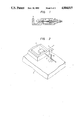
FIG. 1 shows an example of the construction of a laser diode. A reference numeral 1 denotes a laser diode chip fixed to a sub-mount 2 which is in turn secured to a frame 3. On the other hand, an optical fiber 4 passes through a hole formed in the central portion of a supporting post 5 which is fixed at its one end to frame 3. The output end is led to the outside through a hole formed in the frame 3. The position of the light-emitting portion of the laser diode chip 1 fluctuates with respect to the frame 3, due to insufficient precision of machining of the chip and insufficient precision of mounting the chip on the sub-mount. Similarly, the position of the end of the optical fiber fluctuates. In order to obtain a predetermined output from the laser diode, it is necessary that the optical axes of the laser diode chip 1 and the optical fiber 4 are aligned with a precision in the order of 0.1 μm to 1 μm. To this end, hitherto, the alignment has been attained by grasping one end of the supporting post 5, moving the supporting post 5 in the X and Y directions or X, Y and θ directions, thereby moving the end of the optical fiber 4 while plastically deforming the supporting post 5. During this operation, the output from the optical fiber 4 is observed to probe the position where the output value exceeds a predetermined level, thereby attaining optical axis alignment between the optical fiber 4 and the laser diode chip 1. In order to attain automation of this operation, it is necessary to grasp the end of the supporting post 5 by a mechanism having multiple degrees of freedom and to control the mechanism in accordance with the output from the laser diode, thereby effecting plastic deformation of the supporting post.
FIG. 3 shows a mechanism having three degrees of freedom, as an example of the mechanism with multiple degrees of freedom. This mechanism 6 has a fine adjustment device composed of an outer frame 7, intermediate frame 8, inner frame 9 and an end frame 10. The outer frame 7 and the intermediate frame 8 are coupled to each other through a parallel leaf spring mechanism. Similarly, the intermediate frame 8 and the inner frame 9 are coupled to each other through a similar parallel leaf spring mechanism. The outer frame 7 and the intermediate frame 8; and the inner frame 8 and the intermediate frame 9 are adapted to be displaced in X and Y directions by piezoelectric actuators 11 and 12, in proportion to the voltage applied to piezoelectric actuators. The inner frame 9 and the end frame 10 are coupled through a spring mechanism which is constructed in such a manner as to cross at the central points, and are adapted to be actuated by a piezoelectric actuator 13, thereby effecting minute angular movement about the central point (in the θ direction) proportional to the voltage applied to the piezoelectric actuator. A supporting post gripper is fixed to the lower side (not shown) of the end frame 10. The gripper can grip the supporting post 5 so as to deflect the latter in three directions, i.e., X, Y and θ directions. The outer frame 7 is fixed to a stationary member.
FIG. 4 shows the arrangement of the whole portion of the invention. The output from the laser diode 1 is detected by a detector 14 and is sent to a controller 15. The controller 15 computes the amounts of driving of three piezoelectric actuators in accordance with the following method, and applies to each piezoelectric actuator a voltage corresponding to the computed value.
A description will be made hereinunder as to the control sequence in the first embodiment of the invention.
It is assumed here that the position of the gripper when it has just gripped the supporting post 5 is expressed by x0, y0 and θ0, while the output of the laser diode in this state is represented by f0. When the factors x, y and θ have initial values x0, y0 and θ0, the amounts of initial displacement Δx1, Δy1 and Δθ1 are determined. Symbols Δx, Δy and Δθ represent the displacements in x, y and θ directions, while suffix n represents the n-th cycles of movement.
The optical output f detected by the detector 14 through the fiber is determined by x, y and θ.
As the first step, a movement by amount Δx1 is caused and the gradient of the optical power distribution surface is determined by the difference in the optical output between the state before the movement and the state after the movement. ##EQU1## where, f0 and fx1 represent the value of the optical output in the states before and after the movement by the amount Δx1.
Then, a movement by the amount Δy1 is effected to provide the following condition. ##EQU2## where, fx1 and fy1 represent the optical output values obtained in the states before and after the movement by the amount Δy1 and can be determined by measurement. Then a movement by the amount Δθ1 is conducted so that the following condition is obtained. ##EQU3##
After the completion of movements by amounts x, y and θ, the gradient s of the optical power distribution surface and the height h are determined as follows. ##EQU4##
Using the conditions of the formulae (1) to (5), the amounts Δx2, Δy2 and Δθ2 of the second cycle of operation in the x, y and θ directions are determined as follows. ##EQU5##
A, B, j and k are constants the optimum values of which are obtainable through experiments. If the constant A is positive, the movement is caused in such a direction as to reduce s, whereas, when the constant A is negative, the movement is caused in such a direction as to decrease the value s. It is to be noted also that the amount of movement is decreased as the value h is increased.
Similarly, the amounts Δxn, Δyn and Δθn in the x, y and θ directions in the n-h cycles of movement are determined as follows. ##EQU6##
The cycles of movement are further repeated until the number n exceeds a predetermined value or the value s comes down below a predetermined value or the value h exceeds a predetermined value.
Various methods for determining G(=f(s,h)) employing s and h are usable in place of the formula (9).
FIG. 5 shows the flow of the control method described above. More specifically, FIG. 5a shows the result of application of the control method of the invention to a mechanism having two degrees of freedom in which the output f is given as a function of x and y, i.e., as f=e- (x2 +y2) with the angle θ omitted. Numerals appearing in the Figure represents the number of cycles. It will be seen that the output f takes the maximum value of 1 on condition of x=0 and y=0. In this embodiment, conditions of A=0.5, m=0, x0 =y0 =1, Δx1 =0.1 and Δy1 =-0.1 are met. As will be clearly seen from these conditions, the gripper has been brought to the position where the output f takes the maximum value. The output value obtained in this state is shown in FIG. 5b.
In the described embodiment, the movement in respective steps for the purpose of the probing is intended not only for the approach to the designated maximum value but also for the measurement of the gradient in the vicinity of the maximum value point. As a result, an efficient probing is executed because the probing and the measurement of gradient are conducted at one time.
In the severest method, the movement by the amount Δx in the x-axis direction is followed by the movement in the -Δx direction, and a subsequent movement Δy in the y-axis direction is followed by a movement -Δy, and finally a movement is effected in the steepest direction on the x, y plane. The method of the invention is superior to the above-explained severest method in that (1) the number of the moving cycles is smaller, and that (2) number of sharp turns (movement -Δx following the movement Δx means 180° change in the moving direction) is smaller.
A description will be made hereinunder as to the case where the control sequence explained above is applied to displacement of n-th order (x1, . . . , xn), with specific reference to FIG. 6.
The distances (Δx10, Δx20, . . . , Δxn0) for the first cycle of movement are beforehand determined, as well as the level of the optical output (fc) at which the probing is completed and the number Nc of the cycles at which the probing is to be stopped. In Step 104, a movement Δx10 is caused in the direction x1. The amount of change in the optical output is expressed by Δf. The gradient of the optical power distribution surface shown by the far field pattern in the direction x1 is expressed as Δf/Δx10 (Step 106). Then, in Step 108, a movement Δx20 is effected in the direction x2 from the instant point. In a strict sense, it is necessary that a backward driving is effected to return the object to the initial position, i.e, to the position taken before the movement Δx10. Such a backward movement, however, is omitted in view of the fact that the movement Δx10 is negligibly small and in order to shorten the probing time. The inclination during this movement is expressed by Δf/Δx20 (Step 110). Thereafter, the movements Δx30, Δx40, . . . , Δxno are consecutively conducted (Step 112) and inclinations are computed (Step 114). Thereafter, a movement Δx1 is effected in the direction x1. The Δx1 is determined in accordance with the formula Δx1 =Gσf/σx1. The value of inclination calculated immediately after the previous movement in the direction x1 (Δf/Δx1, Δf/Δx10 for the first movement) is used as Δf/Δx10. The amount of change in the optical output in this state is expressed by Δf and the inclination during this movement is given as Δf/Δx1 (Step 118). Then, a movement Δx2 is effected in the direction x2, followed by consecutive movements Δx3, Δx4, . . . , Δxn, with calculation of the inclinations 120-128. The probing is continued in the manner described and is ceased when a predetermined value fc is reached or when a predetermined number of probing cycles is reached.
A second embodiment of the invention will be described hereinunder.
The principle of the second embodiment is as follows. The displacements x1, x2, . . . , xn of n-th order is given as follows.
S=(x.sub.1, x.sub.2, . . . , x.sub.n)                      (16)
In this case, the estimation function f is expressed as follows.
f=f(S)                                                     (17)
Since the value of f (S) is obtained as the optical output at every moment, it is not necessary to provide a practical form of f(S).
The value of the estimation function as obtained when the condition of S=Sm is met is expressed as fm=f(Sm). The gradient em of the estimation function is given by the following formula. ##EQU7## where, x1, x2, . . . , xn are unit vectors of each moving direction of the fine motion mechanism. When the amounts of movement are small, these amounts are expressed as Δx1, Δx2, . . . , Δxn. In this case, the gradient em is given by the following formula. ##EQU8## where, Δfm is the amount of change in the value of the estimation function, which is given by the following formula (20).
Δf.sub.m =f.sub.m -f.sub.m-1 =f(S.sub.m)-f(S.sub.m-1) (20)
As will be seen from formula (20), the gradient em varies largely depending on the value of the estimation function, such that it takes a large value in the region where the estimation function has a large value and a small value in the region where the estimation function takes a small value. Thus, the gradient em is largely varied by the absolute value. In order to avoid this problem, the amount of change in the value of the estimation function is normalized as follows by the value fm-1 of the estimation function as obtained before the movement. ##EQU9##
Using the value of gradient em * of the estimation function thus obtained, the amount δx1, δx2, . . . , δxn of movement effected by the fine motion mechanism are determined in such a manner as to make the estimation function approach the maximum value from the instant position, i.e., in the direction of em *. ##EQU10## wherein A and p are constants (A>0, p≧0).
The fine motion mechanism progressively moves towards the direction of the gradient so that the estimation function value reaches the maximum value. The gradient becomes zero when the maximum value is reached. In this state, the mechanism does not work any more, so that the aligning operation is finished.
In this embodiment, the amount of movement to be achieved by the fine motion mechanism is determined on the basis of the gradient which in turn is obtained by normalizing the amount of change in the evaluation function. According to this arrangement, the mechanism is driven in accordance with the rate of change of the estimation function value rather than the absolute value of the estimation function. In consequence, the large amount of movement given by the fine motion mechanism is large when the mechanism is remote from the position corresponding to the maximum value but is small when the position corresponding to the maximum value has been approached, whereby an efficient probing is obtained.
A practical process in accordance with the second embodiment will be explained with reference to FIG. 7.
The displacements of the mechanism when it has just gripped the supporting post 5 by the gripper are given by X0, Y0 and θ0, while the optical output in this state is represented by f0. In the first cycle, the X-direction actuator is driven (Step 202) in the X direction by an amount corresponding to the amount ΔX1 which is set beforehand, and the optical output in this state is measured to obtain the following condition (Step 204). ##EQU11##
Thereafter, operations for driving by previously set amounts ΔY1 and Δθ1 are conducted both in Y and θ directions, so that the following conditions are derived from respective optical outputs f1Y and f10θ (Steps 206-212). ##EQU12##
Then, the following operations are conducted (Steps 214-244) on the basis of the data shown in formulae (24) to (26).
In the steps 216, 224 and 232, the following averaging operation is carried out to minimize the noise content in the value of the estimation function. ##EQU13##
In formula (27) em *1, . . . , em-l * represent, respectively, the gradients in the cycles which are 1 to l th preceding cycles as counted from the instant position, and are given by the formula (21). Symbols α0 to αl represent the weight coefficients.
The gradient em*X of the optical output fmX in the 3m+1 th cycle (m=1, 2, . . . ) are determined (Step 216) as follows in accordance with the formulae (21) and (27). ##EQU14## Referring to formula (28), the terms Δfm*X, Δfm*Y and Δfm*θ in the right side of this formula should be replaced, in a strict sense, with the values which are obtained by normalizing the amount of change in the optical outputs obtained when the fine motion mechanism is driven simultaneously in all directions X, Y and θ by amounts ΔXm, ΔYm and Δθm. Practically, however, the normalized values can be regarded as being materially the same as the values Δfm*X Δfm*Y and Δfm*θ, so that formula (28) is valid.
Referring now to Formula (29), if the condition of m is met, the following condition is established.
e.sub.m-1 *, X=e.sub.m-2 *, X=. . . . . . =e.sub.m-l *, X  (30)"
and substitute therefor--Regarding formula (29), during the initial stages of the probing control operation wherein a condition 1≦m≦l is met, the values of the gradient in the preceding cycles which are necessary for calculating Em*X in accordance with formula (29) are those in only 1 to m-th cycles. In the initial stages wherein the condition 1≦m≦l is met, the following condition is established for calculating Em*X in accordance with formula (29):
e*.sub.1,X =e*.sub.0,X =e*.sub.m-(m+1),X =. . . =e*.sub.m-l,X (30)
The amount δXm in the X direction is determined in accordance with formula (20) on the basis of the formula (23). ##EQU15##
The values of coefficients α0 to αl, l, A and p appearing in formulae (29) and (32) are optimally determined through experiments.
Subsequently, the fine motion mechanism is moved in the X direction by amount δXm (Step 220) and the (3m+2) th optical output fmY is measured. The gradient Em*Y also is determined (Step 224) as follows. ##EQU16##
Similarly, the amount δYm of movement in the Y direction is determined (Step 226) by the following formulae. ##EQU17##
Then, the fine motion mechanism is actuated (Step 228) by amount δYm in the Y direction and the optical output fmθ for (3m+3) th cycle is measured.
The gradient Em*θ and the amount δθm of movement in the θ direction are determined in accordance with the following formulae. ##EQU18##
Then, Δθm+1 is set as δθm and 1 is added to m so that the process returns to the initial state and then repeated.
This repetitional operation is continued and is stopped when the optical output f has been increased to exceed a predetermined value F ( Steps 222, 230, 238), or when the gradient is decreased to reduce the value √Em*.Em* down below a predetermined value E (Step 242) or when the number m of the probing cycles has been increased to exceed a predetermined number M (Step 204), whereby the optical axis alignment is accomplished.
As has been described, in the embodiment of the invention, not only the movement towards the maximum value but also the determination of the gradient of the estimation function value is conducted in each step during the probing, so that it becomes unnecessary to determine the gradients in all directions, thus providing advantages such as higher efficiency of probing, shortening of the probing time, and reduction in the load on the mechanism.
In addition, since the gradient is determined through normalization of the estimation function, the gradient of the estimation function is estimated without being affected by the absolute value of the estimation function, the requirement for a change in the parameter can be reduced even for devices which involve fluctuation of the output.
In addition, since the gradient is determined taking into account also the gradients in the past, it is possible to absorb any abrupt apparent change in the gradient due to noise, so that the probing can be conducted smoothly even though the control is conducted in accordance with differentiated values.

Claims (11)

What is claimed is:
1. A probing method for effecting optical access alignment of an optical fiber in a laser diode with optical fiber, said method employing a mechanism with a plurality of degrees of freedom, said method comprising the steps of:
driving by predetermined amounts in one-by-one fashion a plurality of actuators for driving said mechanism;
determining change in an optical output from an object in response to the driving of each of the actuators and obtaining a gradient in the optical output on the basis of the change determined;
obtaining an amount of movement for driving each of said actuators on the basis of the gradient in the optical output in an immediately preceding step of driving the same actuator, driving the same actuator by the amount of movement thus obtained, and sequentially measuring the optical output in response to the driving of each actuator; and
determining whether conditions have occurred of said optical output exceeding a first predetermined value or said gradient in the optical output falling below a second predetermined value, stopping the driving of the actuators when one of said conditions has occurred, and repeating the step of driving the actuators in one-by-one fashion when none of said conditions have occurred.
2. A probing method for effecting optical access alignment of an optical fiber in a laser diode with optical fiber, said method employing a mechanism with multiple degrees of freedom, said method comprising the steps of:
driving in one-by-one fashion three actuators for driving a mechanism having three degrees of freedom in horizontal, vertical and rotating directions by predetermined amounts in the horizontal, vertical and rotating directions, respectively;
measuring an optical output from an object and obtaining changes in the optical output in the respective horizontal, vertical and rotating directions in response to the driving of each actuator;
obtaining a gradient in the optical output on the basis of the changes in the optical output in the respective directions;
determining subsequent amounts of movement of the actuators in the horizontal, vertical and rotating direction, respectively, from present positions of the actuators, on the basis of the gradient in such a manner that the gradient takes a minimum value, and driving each actuator to effect the subsequent amounts of movement;
measuring the optical output and obtaining the gradient therein in response to the driving of each actuator; and
deciding whether conditions have occurred of said optical output exceeding a first predetermined value, said gradient in the optical output falling below a second predetermined value or a number of times for driving the actuators exceeding a predetermined number;
stopping the driving of said three actuators when any one of the conditions has occurred; and
repeating the steps of obtaining a gradient, determining amounts of movement and measuring the optical output to determine sequentially the amounts of movement of said actuators and driving each actuator when any of the conditions have not occurred.
3. A probing control apparatus, comprising:
a multiple degree of freedom mechanism having n-degrees of freedom for controlling alignment of an object providing an output having an outer frame coupled via a first parallel leaf spring mechanism with an intermediate frame, said intermediate frame being coupled via a second parallel leaf spring mechanism with an inner frame and said inner frame being coupled via a third spring mechanism with an end frame;
n actuators for actuating said mechanism;
means for detecting changes in the output from said object in response to the operation of each of said actuators; and
control means for computing a command for each of said actuators in accordance with a change in the output detected by said detecting means and an amount of movement of said mechanism, and for controlling each actuator in accordance with said command such that said output from said object takes a maximum value.
4. A probing control apparatus, comprising:
adjustment means having a plurality of frames including one frame exhibiting a central point and a plurality of mechanisms interconnecting said frames to provide multiple degrees of freedom of movement of said adjusting means about said central point, said one frame engaging an optical element effecting an output signal, for controlling deflection of an optical axis of said optical element;
a plurality of actuators for moving said frames relative to each other during discreet adjustment operations in response to commands specifying amounts of movement;
means for detecting the output signal of said optical element; and
control means for computing subsequent commands in accordance with the amounts of movement specified by preceding corresponding ones of said commands and changes in the output signal detected by said detecting means occurring as a result of movement of said frames in response to respective said preceding corresponding ones of said commands during said adjustment operations, and for controlling said actuators in accordance with said subsequent commands to cause said output to attain a maximum value.
5. A probing control apparatus according to claim 4, wherein said adjustment means comprises an outer frame coupled via a first parallel leaf spring mechanism with an intermediate frame, said intermediate frame being coupled via a second parallel leaf spring mechanism with an inner frame and said inner frame being coupled via a third spring mechanism with an end frame exhibiting the central point.
6. A probing control apparatus according to claim 5, wherein said actuators are disposed for individually causing said outer frame to move relative to said intermediate frame, said intermediate frame to move relative to said inner frame, and said inner frame to move relative to said end frame.
7. A probing control apparatus according to claim 4, wherein said control means normalizes change in the output signal detected by said detecting means and computes said subsequent commands on the basis of a normalized change and the amount of movement for one of said actuators contained in a preceding corresponding one of said adjustment operations.
8. A probing control apparatus, comprising:
adjustment means having a plurality of frames including one frame exhibiting a central point and a plurality of mechanism interconnecting said frames to provide multiple degrees of freedom of movement of said adjusting means about said central point, said one frame engaging an optical element effecting an output signal, for controlling deflection of an optical axis of said optical element;
a plurality of actuators disposed to displace said frames relative to the component coordinates of a coordinate system during cycles of adjustment operations in response to commands specifying amounts of movement of said frames by respective ones of said actuators;
means for detecting the output signal of said optical element;
control means for determining changes in the output signal associated with each of said component coordinates for each cycle of said adjustment operations, for determining values of gradients in the output signal relative to amounts of movement for respective ones of said component coordinates contained in preceding commands, for performing averaging routines on corresponding values of the gradients relative to each of said component coordinates, for computing said commands to maximize the values of the output associated with each of said component values by discretely driving said actuators, and for driving said actuators on the basis of said commands.
9. A probing control apparatus according to claim 8, wherein said adjustment means comprises an outer frame coupled by a first parallel leaf spring mechanism with an intermediate frame, said intermediate frame being coupled by a second parallel leaf spring mechanism with an inner frame and said inner frame being coupled by a third spring mechanism with an end frame exhibiting the central point.
10. A probing control apparatus according to claim 9, wherein said actuators are disposed for individually causing said outer frame to move relative to said intermediate frame, said intermediate frame to move relative to said inner frame, and said inner frame to move relative to said end frame.
11. A probing control apparatus according to claim 8, wherein said control means is adapted to normalize change in the output signal detected by said detecting means and to compute said gradients on the basis of a normalized change and the amount of movement for one of said actuators contained in a preceding corresponding one of said adjustment operations.
US06/875,189 1985-06-17 1986-06-17 Probing control method and apparatus for mechanism with multiple degrees of freedom Expired - Fee Related US4884015A (en)

Applications Claiming Priority (4)

Application Number Priority Date Filing Date Title
JP60129806A JPH0652488B2 (en) 1985-06-17 1985-06-17 Optical axis search method for optical fiber
JP60-129806 1985-06-17
JP60-215014 1985-09-30
JP21501485A JPS6275508A (en) 1985-09-30 1985-09-30 Extreme value retrieving system for automatic optical axis aligning device

Publications (1)

Publication Number Publication Date
US4884015A true US4884015A (en) 1989-11-28

Family

ID=26465086

Family Applications (1)

Application Number Title Priority Date Filing Date
US06/875,189 Expired - Fee Related US4884015A (en) 1985-06-17 1986-06-17 Probing control method and apparatus for mechanism with multiple degrees of freedom

Country Status (3)

Country Link
US (1) US4884015A (en)
EP (1) EP0207352B1 (en)
DE (1) DE3682834D1 (en)

Cited By (17)

* Cited by examiner, † Cited by third party
Publication number Priority date Publication date Assignee Title
US4984885A (en) * 1989-12-15 1991-01-15 General Electric Company Method and apparatus for high power optical fiber injection and alignment
US5061039A (en) * 1990-06-22 1991-10-29 The United States Of America As Represented By The United States Department Of Energy Dual axis translation apparatus and system for translating an optical beam and related method
US5191629A (en) * 1990-03-23 1993-03-02 Alcatel N.V. Laser module
US5422725A (en) * 1990-09-17 1995-06-06 Radians Innova Ab Cantilever system for holding and positioning components
US5535297A (en) * 1993-12-16 1996-07-09 Honeywell Inc. Micro-alignment method
US5623337A (en) * 1994-09-28 1997-04-22 Nec Corporation Method capable of quickly adjusting an optical axis of an optical fiber
US5870517A (en) * 1997-10-07 1999-02-09 Integrated Device Technology, Inc. Package including self-aligned laser diode and method of aligning a laser diode
US6074103A (en) * 1996-10-15 2000-06-13 Sdl, Inc. Aligning an optical fiber with electroluminescent semiconductor diodes and other optical components
US6253010B1 (en) * 1998-04-17 2001-06-26 Iolon, Inc. System and method for efficient coupling between optical elements
WO2002067031A2 (en) * 2001-02-16 2002-08-29 Siemens Dematic Electronics Assembly Systems, Inc. Method and system for automated dynamic fiber optic alignment and assembly
US6470023B1 (en) * 2001-03-05 2002-10-22 Terabeam Corporation Optical fiber position controller for multiple degrees of freedom
US6498892B1 (en) 2000-08-03 2002-12-24 Murray R. Harman Positioning device especially for assembling optical components
US6690865B2 (en) * 2000-11-29 2004-02-10 The Furukawa Electric Co., Ltd. Method for aligning laser diode and optical fiber
US20040165839A1 (en) * 2002-12-17 2004-08-26 Photintech, Inc. Method and device for coupling a light emitting source to an optical waveguide
US20150343589A1 (en) * 2014-05-28 2015-12-03 Boe Technology Group Co., Ltd. System and method for automatically adjusting a position of a panel on a chuck
US10746945B1 (en) * 2017-10-09 2020-08-18 Waymo Llc Systems and methods for laser diode alignment
US11042004B1 (en) * 2017-10-23 2021-06-22 Waymo Llc System and method for alignment of optical beams

Families Citing this family (1)

* Cited by examiner, † Cited by third party
Publication number Priority date Publication date Assignee Title
FR2691825A1 (en) * 1992-05-26 1993-12-03 Bernay Automation Teaching device for degrees of liberty of mechanical assembly - has fixed U-frame supporting assembly in two parts which can move about three different axes

Citations (8)

* Cited by examiner, † Cited by third party
Publication number Priority date Publication date Assignee Title
US3808485A (en) * 1971-07-15 1974-04-30 Asahi Optical Co Ltd Manipulator
CA1066426A (en) * 1976-11-29 1979-11-13 Frederick D. King Method and apparatus for alignment of optical fibres with optoelectronic devices
US4191916A (en) * 1977-11-23 1980-03-04 Fujitsu Limited Table positioning system including optical reference position measuring transducer
US4500165A (en) * 1982-04-02 1985-02-19 Codenoll Technology Corporation Method and apparatus for aligning optical fibers
US4514674A (en) * 1983-12-22 1985-04-30 International Business Machines Corporation Electromagnetic X-Y-Theta precision positioner
CA1198797A (en) * 1980-03-27 1985-12-31 Optimetrix Corporation X-y addressable workpiece positioner having an improved x-y address indicia sensor
US4664524A (en) * 1983-09-24 1987-05-12 The President Of Nagoya University Optical self-alignment system
US4707067A (en) * 1984-02-22 1987-11-17 Siemens Aktiengesellschaft Opto-electronic module housing

Family Cites Families (1)

* Cited by examiner, † Cited by third party
Publication number Priority date Publication date Assignee Title
EP0036026B1 (en) * 1980-03-10 1986-11-12 Eaton-Optimetrix Inc. Addressable device for the positioning of a work-piece

Patent Citations (8)

* Cited by examiner, † Cited by third party
Publication number Priority date Publication date Assignee Title
US3808485A (en) * 1971-07-15 1974-04-30 Asahi Optical Co Ltd Manipulator
CA1066426A (en) * 1976-11-29 1979-11-13 Frederick D. King Method and apparatus for alignment of optical fibres with optoelectronic devices
US4191916A (en) * 1977-11-23 1980-03-04 Fujitsu Limited Table positioning system including optical reference position measuring transducer
CA1198797A (en) * 1980-03-27 1985-12-31 Optimetrix Corporation X-y addressable workpiece positioner having an improved x-y address indicia sensor
US4500165A (en) * 1982-04-02 1985-02-19 Codenoll Technology Corporation Method and apparatus for aligning optical fibers
US4664524A (en) * 1983-09-24 1987-05-12 The President Of Nagoya University Optical self-alignment system
US4514674A (en) * 1983-12-22 1985-04-30 International Business Machines Corporation Electromagnetic X-Y-Theta precision positioner
US4707067A (en) * 1984-02-22 1987-11-17 Siemens Aktiengesellschaft Opto-electronic module housing

Cited By (21)

* Cited by examiner, † Cited by third party
Publication number Priority date Publication date Assignee Title
US4984885A (en) * 1989-12-15 1991-01-15 General Electric Company Method and apparatus for high power optical fiber injection and alignment
US5191629A (en) * 1990-03-23 1993-03-02 Alcatel N.V. Laser module
US5061039A (en) * 1990-06-22 1991-10-29 The United States Of America As Represented By The United States Department Of Energy Dual axis translation apparatus and system for translating an optical beam and related method
US5422725A (en) * 1990-09-17 1995-06-06 Radians Innova Ab Cantilever system for holding and positioning components
US5535297A (en) * 1993-12-16 1996-07-09 Honeywell Inc. Micro-alignment method
US5623337A (en) * 1994-09-28 1997-04-22 Nec Corporation Method capable of quickly adjusting an optical axis of an optical fiber
US6074103A (en) * 1996-10-15 2000-06-13 Sdl, Inc. Aligning an optical fiber with electroluminescent semiconductor diodes and other optical components
US5870517A (en) * 1997-10-07 1999-02-09 Integrated Device Technology, Inc. Package including self-aligned laser diode and method of aligning a laser diode
US6253010B1 (en) * 1998-04-17 2001-06-26 Iolon, Inc. System and method for efficient coupling between optical elements
US6498892B1 (en) 2000-08-03 2002-12-24 Murray R. Harman Positioning device especially for assembling optical components
US6690865B2 (en) * 2000-11-29 2004-02-10 The Furukawa Electric Co., Ltd. Method for aligning laser diode and optical fiber
US20020131729A1 (en) * 2001-02-16 2002-09-19 Higgins Leo M. Method and system for automated dynamic fiber optic alignment and assembly
WO2002067031A3 (en) * 2001-02-16 2003-11-20 Siemens Dematic Electronics As Method and system for automated dynamic fiber optic alignment and assembly
WO2002067031A2 (en) * 2001-02-16 2002-08-29 Siemens Dematic Electronics Assembly Systems, Inc. Method and system for automated dynamic fiber optic alignment and assembly
US6470023B1 (en) * 2001-03-05 2002-10-22 Terabeam Corporation Optical fiber position controller for multiple degrees of freedom
US20040165839A1 (en) * 2002-12-17 2004-08-26 Photintech, Inc. Method and device for coupling a light emitting source to an optical waveguide
US7114860B2 (en) * 2002-12-17 2006-10-03 Photintech, Inc. Method and device for coupling a light emitting source to an optical waveguide
US20150343589A1 (en) * 2014-05-28 2015-12-03 Boe Technology Group Co., Ltd. System and method for automatically adjusting a position of a panel on a chuck
US9358651B2 (en) * 2014-05-28 2016-06-07 Boe Technology Group Co., Ltd. System and method for automatically adjusting a position of a panel on a chuck
US10746945B1 (en) * 2017-10-09 2020-08-18 Waymo Llc Systems and methods for laser diode alignment
US11042004B1 (en) * 2017-10-23 2021-06-22 Waymo Llc System and method for alignment of optical beams

Also Published As

Publication number Publication date
DE3682834D1 (en) 1992-01-23
EP0207352B1 (en) 1991-12-11
EP0207352A3 (en) 1987-03-18
EP0207352A2 (en) 1987-01-07

Similar Documents

Publication Publication Date Title
US4884015A (en) Probing control method and apparatus for mechanism with multiple degrees of freedom
EP0180610B1 (en) Improvement relating to coordinate positioning apparatus
US5511930A (en) Precision positioning apparatus
US20020029119A1 (en) Correction method for a coordinate measuring apparatus
US6460711B1 (en) Suspension type hoisting apparatus
EP0486787A1 (en) Multi-bar parallelogram-type positioner
CN104810307A (en) Wafer handling traction control system
Hirzinger et al. Multisensory robots and sensor-based path generation
JPS61239164A (en) Optical seismoscope
CN113510708A (en) Contact industrial robot automatic calibration system based on binocular vision
CN108871307A (en) The automatic direct-coupling device of Y waveguide chip based on image recognition and optical power feedback
US4702652A (en) Advanced memory type profiling control method for a machine tool
Enikov et al. Microassembly experiments with transparent electrostatic gripper under optical and vision-based control
US4956789A (en) Method and apparatus for driving a servo system while suppressing residual vibration generated during position control
US6206266B1 (en) Control method for wire bonding apparatus
Tanaka et al. Automatic measurement and control of the attitude of crane lifters: Lifter-attitude measurement and control
Bonen et al. A novel electrooptical proximity sensor for robotics: Calibration and active sensing
US5550483A (en) High speed test probe positioning system
Everett et al. A sensor used for measurements in the calibration of production robots
CN107447966A (en) Metope position monitoring and control apparatus and method
CN1645045A (en) Part length measurement technique using two or three proximity sensors
Suzuki et al. Position and force control of flexible manipulator with position sensitive device
Samuel et al. Novel force observer for precise force estimation using force sensor
JPS6275508A (en) Extreme value retrieving system for automatic optical axis aligning device
US9959900B1 (en) Compensating tracking error signal offset in optical tape storage systems

Legal Events

Date Code Title Description
AS Assignment

Owner name: HITACHI, LTD., 6, KANDA SURUGADAI 4-CHOME, CHIYODA

Free format text: ASSIGNMENT OF ASSIGNORS INTEREST.;ASSIGNORS:SUGIMOTO, KOICHI;HIRABAYASHI, HISAAKI;MASUI, TOMOYUKI;REEL/FRAME:004566/0450

Effective date: 19860516

FEPP Fee payment procedure

Free format text: PAYOR NUMBER ASSIGNED (ORIGINAL EVENT CODE: ASPN); ENTITY STATUS OF PATENT OWNER: LARGE ENTITY

FPAY Fee payment

Year of fee payment: 4

REMI Maintenance fee reminder mailed
LAPS Lapse for failure to pay maintenance fees
FP Lapsed due to failure to pay maintenance fee

Effective date: 19971203

STCH Information on status: patent discontinuation

Free format text: PATENT EXPIRED DUE TO NONPAYMENT OF MAINTENANCE FEES UNDER 37 CFR 1.362