US488366A - pieper - Google Patents
pieper Download PDFInfo
- Publication number
- US488366A US488366A US488366DA US488366A US 488366 A US488366 A US 488366A US 488366D A US488366D A US 488366DA US 488366 A US488366 A US 488366A
- Authority
- US
- United States
- Prior art keywords
- hammer
- lever
- sear
- pivot
- frame
- Prior art date
- Legal status (The legal status is an assumption and is not a legal conclusion. Google has not performed a legal analysis and makes no representation as to the accuracy of the status listed.)
- Expired - Lifetime
Links
Images


Classifications
-
- F—MECHANICAL ENGINEERING; LIGHTING; HEATING; WEAPONS; BLASTING
- F41—WEAPONS
- F41A—FUNCTIONAL FEATURES OR DETAILS COMMON TO BOTH SMALLARMS AND ORDNANCE, e.g. CANNONS; MOUNTINGS FOR SMALLARMS OR ORDNANCE
- F41A17/00—Safety arrangements, e.g. safeties
- F41A17/06—Electric or electromechanical safeties
- F41A17/063—Electric or electromechanical safeties comprising a transponder
Definitions
- My invention relates to fire-arms, and it consists in certain new and useful constructions and combination of the several parts of the lock mechanism of the same, substantially as hereinafter described and claimed. It is especially adapted for use in guns having three barrels although some features of it may be applied to guns having one or two barrels, if so desired.
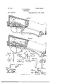
- Figure 1 shows a part of the gun stock and frame, a portion of which is in vertical longitudinal section on the dotted line y-y of Fig. 9. and having the hammer on half cock, which is the position of safety.
- Fig. 2 is the same as Fig. 1 with the hammer cocked ready for firing.
- Fig. 3 shows a portion of the same gun stock partly in vertical longitudinal section on line zz of Fig. 9, with the hammer at half cook or safety position.
- Fig. 4 is the same as Fig. 3, with the hammer cocked ready for firing.
- Figs. 5 and 6 show a modification of the mechanism of Figs.
- Figs. 7 and 8 show another modification designed to accomplish the same result.
- Fig. 9 is a top plan view of a portion of the gun stock and barrels, showing the relative position of the hammers to each other, in full and dotted lines.
- Figs. 10 to inclusive are detail views of the lock action shown in Figs. 1 and 2, for the upper barrel of the gun.
- Figs. 16 to 24: inclusive are detail views of the lock action shown in Figs. 3 and 4 for the lower barrels of the gun.
- FIG. 25 and 26 show the method of securing the barrels in a solid block of metal forming the chambers at the breech, being respectively side and end views, partly in section, of the same.
- Figs. 27 and 28 are respectively side and end views of the muzzle end of the barrels, showing the method of sccu ring them in parallel relation to each other.
- the portions of the gun shown in the drawings are of a three barrel gun, having two barrels side by side and the third barrel on top of and between the other two, as more specially shown in Figs. 9 and 25 to 28 inclusive.
- l is the upper barrel of the gun and 2, 2, are the lower barrels side by side.
- the lock is arranged to show a hammer for firing the upper barrel above the breech piece, and for two hammerless barrels, 2 c. with the hammers concealed in the breech, for the lower barrels.
- A is the hammer of the upperbarrel l, which is mounted in a slot in the breech frame so as to be exposed through it, and it swings on the pivot 5 attached to the frame and is cocked by hand in the usual manner.
- B is the mainspring of this hammer, which is located in a recess in the frame forward of the hammer, extending up and down and bearing upon the portion which projects below the pivot 5.
- This hammer is provided with a cam projection, G, on its front side, which comes against the mainspring B when the hammer falls upon the cartridge, and causes it to rebound slightly so as to throw the sear, G, into the half cook or safety notch.
- the sear O is mounted upon the pivot, 6, in the frame and has a tail piece, D, extending backward from the pivot.
- the vertical piston, E To this is attached the vertical piston, E, by the pivot 7, which depends downward over the triggers 8, 9, in such a position that its lower end will come in contact with either trigger when they are raised sufficiently high, under the conditions allowed by the mechanism as hereinafter described.
- the triggers 8 and 9 lie side by side, working through a slot in the trigger plate and turning upon a pivot, 10, attached thereto.
- sear C is held in contact with the hammer A, and the lower end of the piston E is also held in position to make contact with the triggers 8, 9, by means of a spring, F, attached to the frame and having its bifurcated end bearing upon the pin, 11, on each side of the piston E.
- the lower end of the piston E extends downward between the scars of the hammers of the lower barrels through a space left between them on the rear side of their pivot, which space is shown in Fig. 22.
- the tail portions of the sears for the lower barrel locks are raised up as hereinafter described, so that either trigger may lift the piston E and fire the upper barrel, but when the hammers of the lower barrels are cooked the tail ends of their sears swing downward below the lower end of the piston E, and in the paths of the triggers 8 and 9, so that they cannot possibly reach the piston E and fire the upper barrel.
- the upper barrel can, therefore, only be fired when the locks of the lower barrels are on the half cook or safety position.
- the link, M under the shoulder of which at its upper end the upper part of the mainspring, K, engages, being formed like a hook for that purpose.
- This mainspring is formed of two parts joined together at their rearward end, which is inserted in a slot, L, in the frame and thus held in proper position.
- the other portion K of the mainspring has a bevel, 14, on its outer end, which comes in contact with a corresponding bevel, N, on the tail of the hammer when the hammer falls upon the cartridge, so as to rebound the hammer and automatically throw the sear, 1, into engagement with its notch in the tail of the hammer.
- the sear I is hung bythe pivot, 15, in the outer bifurcated end of the lever, H, which is hung upon the pivot, 16, in the trigger plate, 17.
- This bifurcated end of the lever H carries both searsI on the same pivot, as shown in Fig. 22, in position to engage with the hammers 12 of the lower barrels.
- the lever H has its bent outer end passing downward through a slot in the frame, alongside of the trigger guard, 18, where it can be lifted by the finger when it is desired to cock the hammers of the lower barrels.
- Each searI has a tail piece, 0, which extends backward from its pivot, 15, over the upward path of the corresponding trigger 8 or 9, so as to enable the trigger to lift the sear out of its notch in the hammer when that barrel of the gun is to be fired.
- a depending spring, U is provided with a button, 21, on its lower end, which passes through the slot, 22, in the pitman Q, as the latter is moved upward, allowing the button to spring under the shoulder at the end of the slot after it has passed through the latter. This holds the pitman Q and lever H up in position, cooking the hammers, until the button 21 is released by springing it back with the finger, when the pitman and lever may be drawn downward again.
- the operation of the lock mechanism is as followsz-The lever H is drawn upward as shown in Fig. 4. This straightens the knuckle joint formed by the sear I and cooks the hammers 12, 12. Either trigger 8 or 9 is thus pulled, according to which barrel is wished to fire. This presses up the tail piece, 0, of the sear I and moves the point of the latter downward out of its trigger notch. WVhen the hammer descends, the shoulder N upon it strikes the shoulder, 11, on the mainspring and the member, K, of the latter throws down the lever H by its pressure on the shoulder, 19, and rebounds the hammer by striking the shoulder N, causing the sear to again enter its notch in the hammer. When the lever H is down to the position shown in Fig. 3, it is impossible for the triggers to come in contact with the tail pieces 0 of the scars, I, to disengage the sears from their hammers 12,
- the lock mechanism of the lower hammer 12 is applicable to a double-barrel ham merless gun, i. 6. one with concealed hammers, separately from the third barrel and its hammer.
- the beveled cam, 20 is employed on the member, K, of the mainspring the lever H will not be thrown down automatically by the firing of one barrel of the gun,and the same is true when thespring U and its button 21 are employed, and both of the lower barrels may be fired in succession without manipulating the lever H; the latter must then be moved by the gunner to fire the third barrel. It will thus be seen that great safety and convenience is combined with the extreme simplicity of the lock mechanism.
- Each of the three hammers 12, 12 and A are mounted in slots in the frame of the arm so as to be isolated from each other.
- the bearing point of the shoulder, 19, is also so nearly above the pivot 16, when the hammeris cocked, that it exerts comparatively no force to move lever H until the trigger is pulled when the shoulder is formed as in Figs. 3 and at. I am, therefore, enabled to employ the lever I-I without friction devices to hold it in place usually, only employing the friction cam, 20, or the catch 21 in special cases, where great security is desired.
Landscapes
- Engineering & Computer Science (AREA)
- General Engineering & Computer Science (AREA)
- Toys (AREA)
Description
(No Model.) 4 Sheets-Shet 1. H. PIEPER. GUN LOCK Patented Dec. 20
4 Sheets-Sheet 2.
(No Model.)
H. PIEPER.
GUN LOCK.
No. 488,366. Patented Dec. 20, 1892.
(No Model.) 4 Sheets-Sheet 3.
H. PIBPER.
GUN- LOOK.
Patented Dec. 20, 1892.
- 4 Sheets-Sheet 4.. H. PIEPER.
GUN LOCK.
(No Model.)
Patented Dec. 20, 1892.
mlllll .I
IIIIN ra'rns ATENT GUN-LOCK.
SPECIFICATION forming part of Letters Patent No. 488,366, dated December 20, 1892.
Application filed February 1, 1892. Serial No. 420,021. (No model.) Patented in Belgium December 12, 1890, No. 93,605, and in Germany February 17, 1891, No- 58,675.
To all whom it may concern.-
Be it known that I, HENRI PIEPER, of Liege, in the Kingdom of Belgium, have invented a new and useful Improvement in Firearms, (patented in Belgium December 12, 1890, No. 93,605, and in Germany February 17, 1891, No. 58,675,) of which the following is a specification.
My invention relates to fire-arms, and it consists in certain new and useful constructions and combination of the several parts of the lock mechanism of the same, substantially as hereinafter described and claimed. It is especially adapted for use in guns having three barrels although some features of it may be applied to guns having one or two barrels, if so desired.
In the drawings: Figure 1 shows a part of the gun stock and frame, a portion of which is in vertical longitudinal section on the dotted line y-y of Fig. 9. and having the hammer on half cock, which is the position of safety. Fig. 2 is the same as Fig. 1 with the hammer cocked ready for firing. Fig. 3 shows a portion of the same gun stock partly in vertical longitudinal section on line zz of Fig. 9, with the hammer at half cook or safety position. Fig. 4 is the same as Fig. 3, with the hammer cocked ready for firing. Figs. 5 and 6 show a modification of the mechanism of Figs. 3 and 4., in which the form of the mainspring and cooking lever are arranged to hold the hammer in a cocked position without danger 0f disarrangement. Figs. 7 and 8 show another modification designed to accomplish the same result. Fig. 9 is a top plan view of a portion of the gun stock and barrels, showing the relative position of the hammers to each other, in full and dotted lines. Figs. 10 to inclusive are detail views of the lock action shown in Figs. 1 and 2, for the upper barrel of the gun. Figs. 16 to 24: inclusive are detail views of the lock action shown in Figs. 3 and 4 for the lower barrels of the gun. Figs. 25 and 26 show the method of securing the barrels in a solid block of metal forming the chambers at the breech, being respectively side and end views, partly in section, of the same. Figs. 27 and 28 are respectively side and end views of the muzzle end of the barrels, showing the method of sccu ring them in parallel relation to each other.
The portions of the gun shown in the drawings are of a three barrel gun, having two barrels side by side and the third barrel on top of and between the other two, as more specially shown in Figs. 9 and 25 to 28 inclusive.
l is the upper barrel of the gun and 2, 2, are the lower barrels side by side. The lock is arranged to show a hammer for firing the upper barrel above the breech piece, and for two hammerless barrels, 2 c. with the hammers concealed in the breech, for the lower barrels.
3 is the metal breech frame of the gun, secured to the barrels in the ordinary way so that they may tilt down for loading, and to this the wooden stock, 4, is attached in the usual manner.
A is the hammer of the upperbarrel l, which is mounted in a slot in the breech frame so as to be exposed through it, and it swings on the pivot 5 attached to the frame and is cocked by hand in the usual manner. B is the mainspring of this hammer, which is located in a recess in the frame forward of the hammer, extending up and down and bearing upon the portion which projects below the pivot 5. This hammer is provided with a cam projection, G, on its front side, which comes against the mainspring B when the hammer falls upon the cartridge, and causes it to rebound slightly so as to throw the sear, G, into the half cook or safety notch. The sear O is mounted upon the pivot, 6, in the frame and has a tail piece, D, extending backward from the pivot. To this is attached the vertical piston, E, by the pivot 7, which depends downward over the triggers 8, 9, in such a position that its lower end will come in contact with either trigger when they are raised sufficiently high, under the conditions allowed by the mechanism as hereinafter described. The triggers 8 and 9 lie side by side, working through a slot in the trigger plate and turning upon a pivot, 10, attached thereto. The
sear C is held in contact with the hammer A, and the lower end of the piston E is also held in position to make contact with the triggers 8, 9, by means of a spring, F, attached to the frame and having its bifurcated end bearing upon the pin, 11, on each side of the piston E. The lower end of the piston E extends downward between the scars of the hammers of the lower barrels through a space left between them on the rear side of their pivot, which space is shown in Fig. 22. When the hammers of the lower barrels are on half cock the tail portions of the sears for the lower barrel locks are raised up as hereinafter described, so that either trigger may lift the piston E and fire the upper barrel, but when the hammers of the lower barrels are cooked the tail ends of their sears swing downward below the lower end of the piston E, and in the paths of the triggers 8 and 9, so that they cannot possibly reach the piston E and fire the upper barrel. The upper barrel can, therefore, only be fired when the locks of the lower barrels are on the half cook or safety position.
12 is the hammer of one of the lower barrels which are with their lock mechanisms substantially alike. It is mounted on the pivot, 13, attached to the trigger plate of the frame, and its nose reaches the cartridge through a slot of proper form in the breech.
piece, opposite the proper part of the cartridge. To the tail end of this hammer is attached the link, M, under the shoulder of which at its upper end the upper part of the mainspring, K, engages, being formed like a hook for that purpose. This mainspring is formed of two parts joined together at their rearward end, which is inserted in a slot, L, in the frame and thus held in proper position. The other portion K of the mainspring has a bevel, 14, on its outer end, which comes in contact with a corresponding bevel, N, on the tail of the hammer when the hammer falls upon the cartridge, so as to rebound the hammer and automatically throw the sear, 1, into engagement with its notch in the tail of the hammer. These several operations are performed by the following construction of the mechanism:The sear I is hung bythe pivot, 15, in the outer bifurcated end of the lever, H, which is hung upon the pivot, 16, in the trigger plate, 17. This bifurcated end of the lever H carries both searsI on the same pivot, as shown in Fig. 22, in position to engage with the hammers 12 of the lower barrels. The lever H has its bent outer end passing downward through a slot in the frame, alongside of the trigger guard, 18, where it can be lifted by the finger when it is desired to cock the hammers of the lower barrels. The scar I and the lever H, by their method of pivot ing together, form what is commonly known as a knuckle joint, which, when the end of the lever is lifted by the finger outside of the frame, exerts great power upon the hammers and cocks them very easily. Each searI has a tail piece, 0, which extends backward from its pivot, 15, over the upward path of the corresponding trigger 8 or 9, so as to enable the trigger to lift the sear out of its notch in the hammer when that barrel of the gun is to be fired. \Vhen the sear swings downward as it is being lifted out of its notch in the hammer, its motion is arrested by a projection, P, on the trigger plate, which prevents the trigger from moving upward far enough to strike the piston, E, of the upper hammer A. This affords perfect security against firing the upper barrel of the gun while the lower barrel is being fired. When the lever His drawn downward to the position shown in Fig. 3, the member K of the mainspring comes in contact with the shoulder, N, on the hammer and rebounds the hammer so as to cause the sear to enter its notch again. The shoulders 19 on the lever H swing under the member, K, of the mainspring when the lever is lifted to the position shown in Fig. 4, and prevents this member from interfering with the falling of the hammer so as to strike the cartridge when the gun is fired. WVhen, however, the lever H is in the position shown in Fig. 3, the contact of the member K of the mainspringwith the shoulder, N, on the hammer effectually prevents the latterfrom striking the cartridge and accidentally firing the gun.
To the outer end of the lever, 11, I have shown the pitman Q to be pivoted, and the outer end of this pitman slides in a slot, '1, in the stock of the gun by means of a cross pin or roller S, working in the slot. By drawing the pitman, Q, backward the lever H will be raised from the position shown in Fig. 3 to that in Fig. 4:, and the hammers 12,12, of the lower barrels will be cocked. Each hammer may then be discharged upon its cartridge by pulling its corresponding trigger. In case it is desired to drop the hammers again without discharging either barrel, the lever H can be drawn downward, which drops the hammers back easily to the position in Fig. 3. As will be observed, when the mechanism is in this position the tail parts, 0, of the sears I rise high enough to allow either trigger to reach and operate the piston, E, of the upper hammer, as before mentioned. The lock mechanism of the lower hammers thus forms an effective guard against accidental discharge of the upper barrel.
In order to insure the lever H remainingin the position shown in Fig. 4 with the hammers 12, 12, cocked, I have provided on the lower member, K, of the mainspring a camshaped projection, 20, having a double bevel and I have also provided a corresponding double bevel on the shoulder 19 of the lever 1-1. These double bevcls are so arranged that those on one side of each shoulder will be in contact when the lever is down as shown in Fig. 5, and the shoulders will pass by each other when lever H is raised so as to bring their opposite bevels in contact as shown in Fig. 6. In either position shown in Fig. 5 or 6, these shoulders resist the shifting of the lever H with considerable force, so as to prevent the gun from being accidentallycocked,
IIO
oruncocked, without the operation of the gunner on the lever. Another method of accomplishing this is shown in Figs. 7 and 8, where a depending spring, U, is provided with a button, 21, on its lower end, which passes through the slot, 22, in the pitman Q, as the latter is moved upward, allowing the button to spring under the shoulder at the end of the slot after it has passed through the latter. This holds the pitman Q and lever H up in position, cooking the hammers, until the button 21 is released by springing it back with the finger, when the pitman and lever may be drawn downward again.
The operation of the lock mechanism is as followsz-The lever H is drawn upward as shown in Fig. 4. This straightens the knuckle joint formed by the sear I and cooks the hammers 12, 12. Either trigger 8 or 9 is thus pulled, according to which barrel is wished to fire. This presses up the tail piece, 0, of the sear I and moves the point of the latter downward out of its trigger notch. WVhen the hammer descends, the shoulder N upon it strikes the shoulder, 11, on the mainspring and the member, K, of the latter throws down the lever H by its pressure on the shoulder, 19, and rebounds the hammer by striking the shoulder N, causing the sear to again enter its notch in the hammer. When the lever H is down to the position shown in Fig. 3, it is impossible for the triggers to come in contact with the tail pieces 0 of the scars, I, to disengage the sears from their hammers 12,
2, because the triggers will first come in contact with the piston E. In this position, therefore, the upper barrels may be fired by cocking the upper hammer by hand outside the frame. The lock mechanism of the lower hammer 12 is applicable to a double-barrel ham merless gun, i. 6. one with concealed hammers, separately from the third barrel and its hammer. When the beveled cam, 20, is employed on the member, K, of the mainspring the lever H will not be thrown down automatically by the firing of one barrel of the gun,and the same is true when thespring U and its button 21 are employed, and both of the lower barrels may be fired in succession without manipulating the lever H; the latter must then be moved by the gunner to fire the third barrel. It will thus be seen that great safety and convenience is combined with the extreme simplicity of the lock mechanism. Each of the three hammers 12, 12 and A are mounted in slots in the frame of the arm so as to be isolated from each other.
In order to attach the barrels 1 and 2, 2, together more accurately and substantially than with solder or brazing, and especially to secure them in perfect parallelism to each other, which is of the highest importance, I adopt the following method of securing themz-I form the cartridge chambers for breech loading in the solid steel block, V, into the front end of which the barrels 1, 2, 2, are screwed so that their bores coincide with their respective chambers, as shown in section in Fig. 25. At the muzzle end the barrels are slipped into the metal block, X,being turned down so that the block coincides with their exteriors. Between the blocks V and X the usual filling pieces or braces 30, 30, are then brazed or soldered in, so as to impart a finish to the gun and prevent dirt &;c. from getting between the barrels, the blocks V and X holding the barrels perfectly in relative position to each other while the brazing or soldering is being performed. The blocksVandXfit snuglyagainst the ends of'the filling pieces and are brazed thereto, affording additional security. It will be observed that when the hammer 12 is cooked, the pivot 16 of the lever H, the pivot 15 of the sear I, and the nose of the sear which rests in the notch of the hammer, are substantially in the same right line, thus causing the pressure of the mainspring on the hammer to come directly upon the pivot 16 and to have no tendency to move the lever H until the trigger is pulled. The bearing point of the shoulder, 19, is also so nearly above the pivot 16, when the hammeris cocked, that it exerts comparatively no force to move lever H until the trigger is pulled when the shoulder is formed as in Figs. 3 and at. I am, therefore, enabled to employ the lever I-I without friction devices to hold it in place usually, only employing the friction cam, 20, or the catch 21 in special cases, where great security is desired.
What I claim as new and of my invention 1. The combination of the hammer 12, provided with its notch for the sear, the mainspring K, arranged to impel the hammer upon the cartridge, the lever H, pivoted at 16 in the frame, the sear I having one end formed to engage with the hammer notch, and pivoted at 15 in the lever H with its tail end projecting beyond the pivot, and the trigger, 8, pivoted in the frame and arranged to engage with the projecting tail end of the sear to release the latter, substantially as described.
2. The combination of the hammer, 12, provided with its notch for the sear and with the shoulder N, the mainspring K arranged to impel the hammer upon the cartridge, the spring K arranged to bear upon the shoulderN and rebound the hammer, the lever H pivoted at 16 in the frame, and having the shoulder 19 arranged to lift the spring K off of shoulder N, the sear I having one end formed to engage with the hammer notch and pivoted at 15 in the lever H, with its tail end projecting beyond the pivot, and the trigger 8 pivoted in the frame and arranged to engage with the projecting tail end of the sear to release the latter, substantially as described.
3. The combination of the hammer 12 provided with its notch for the sear, the mainspring K arranged to impel the hammer upon the cartridge, the lever H, pivoted at 16 in the frame, and the sear I having one end formed to engage with and turn in the hammer notch as a pivot, and pivoted at 15 in the lever H in position to bring the lever pivot 16, the pivot 15, and the point of the sear substantially in a right line when the hammer is cooked, substantially as described.
4:. The combination of the hammer 12 provided with its notch for the sear, and with the shoulder N, the mainspring K arranged to impel the hammer upon the cartridge, the spring K arranged to bear on shoulder N, the lever H pivoted at 16, and provided with the shoulder 19 arranged to engage with and lift spring K off of shoulder N, the sear I pivoted in lever H and arranged to engage with the hammer, and the trigger arranged to release the sear and discharge the hammer, substantially as described.
5. The combination of two hammers mounted in the frame side by side, respectively having notches for their scars, and each provided with a mainspring, K, arranged to independently impel it upon the cartridge, and a single lever, H, pivoted at 16 in the frame and carrying two sears I, I, pivoted in its outer end and arranged to respectively engage with the two hammers, and two triggers 8, 9, each arranged to engage with one of said sears and discharge its hammer from engagement therewith, substantially as described.
6. The combination of the lower hammer 12, provided with a sear notch, the lever H pivoted in the frame, the sear I pivoted in the lever and arranged to engage with said hammer, the upper hammer A, its sear O, and attached piston E depending alongside of said searI, and the trigger 8 adapted to be broughtin contact with either the searI or the piston E, when either is within the range of movement of the trigger substantially as described.
7. The combination of the lower hammer 12 provided with a scar notch, the lever H pivoted in the frame, the sear I pivoted in the lever and arranged to engage with said hammer, the upper hammer A, its sear O, and the attached piston E depending alongside of said sear I, the trigger 8 adapted to be brought in contact with either sear I or piston E, when brought within its range of movement, and the shoulder P on the frame, arranged to limit the movement of the sear I and arrest the trigger before it reaches the piston, substantially as described.
8. The combination of two lower hammers 12, 12, each provided with a sear notch, the lever H pivoted in the frame, two sears I, I, pivoted in the lever and respectively arranged to engage with said hammers, the upper hammer A, its sear O and the attached piston, E, depending between said sears I, I, and two triggers S, 9, each arranged to engage with one of said sears I and the depending piston E, when respectively brought within its range of movement, substantially as described.
9. The combination of two hammers 12, 12, mounted side by side in the frame, each provided with its notch for the sear and mainspring arranged to impel it upon the cartridge, the lever H pivoted at 16 in the frame, and
' two sears I, I, each having one end formed to engage with and turn in its hammer notch as a pivot, and pivoted at 15 in lever H in position to bring the lever pivot 16, the sear pivot 15, and the point of the sear substantially in a right line when the hammer is cooked, whereby one of said sears may be discharged from its hammer and discharge the latter, while the other hammer is held in a cocked position ready to be discharged,substantially as described.
10. The combination of the hammer 12 provided with its notch for the sear, the mainspringK arranged to impel the hammer upon the cartridge, the lever H pivoted at 16 in the frame, the sear I having one end formed to engage with and turn in the hammer notch, and pivoted at 15 in lever H in position to bring the lever pivot 16, the pivot 15 and the point of the sear substantially in a right line when the hammeris cooked, and a spring provided with a shoulder or catch arranged to engage with a shoulder on the lever and hold it in this position while the sear is being released and the hammer discharged, substantially as described.
11. The combination of the hammer 12 provided with its notch for the sear, the mainspring K arranged to impel the hammer upon the cartridge, the lever H pivoted at 16 in the frame and provided with the shoulder 19, the sear I having one end formed to engage with and turn in the hammer notch, and pivoted at 15 in lever H in position to bring the lever pivot 16, the pivot 15 and the point of the sear substantially in a right line when the hammer is cooked, and the spring K provided with the shoulder, 20, arranged to engage with the shoulder 19 and hold the lever in its position while the sear is being released and the hammer discharged, substantially as described.
12. The combination of the upper hammer A provided with sear notches, its mainspring B mounted in the frame on the forward side of it, the sear 0 provided with the attached piston E depending into the path of movement of the trigger, the lower hammer 12 provided with its sear notch, with its mainspring K mounted in the frame on the rear side of it, the lever H pivoted in the frame and provided with the sear I pivoted thereto, and having its tail end arranged to come in the path of the trigger when the lower hammer is at full cock, and to be lifted out of the path of the trigger and above the lower end of piston E when the lower hammer is at safety cock, whereby the discharging of the upper hammer and that of the lower hammer by the same trigger are rendered independent of each other, substantially as described.
HENRI PIEPER.
Witnesses:
H. WERLEMANN, J. GRoss.
ITO
Publications (1)
| Publication Number | Publication Date |
|---|---|
| US488366A true US488366A (en) | 1892-12-20 |
Family
ID=2557212
Family Applications (1)
| Application Number | Title | Priority Date | Filing Date |
|---|---|---|---|
| US488366D Expired - Lifetime US488366A (en) | pieper |
Country Status (1)
| Country | Link |
|---|---|
| US (1) | US488366A (en) |
-
0
- US US488366D patent/US488366A/en not_active Expired - Lifetime
Similar Documents
| Publication | Publication Date | Title |
|---|---|---|
| US520468A (en) | Revolver-lock mechanism | |
| US361100A (en) | Lock device for fire-arms | |
| US488366A (en) | pieper | |
| US2341033A (en) | Firearm | |
| US1511262A (en) | Automatic firearm | |
| US728739A (en) | Automatic firearm. | |
| US202126A (en) | Improvement in breech-loading fire-arms | |
| US756039A (en) | Breech-loading firearm. | |
| US594863A (en) | Otto p | |
| US441389A (en) | Combined rifle and shotgun | |
| US793692A (en) | Safety device for firearms. | |
| US323837A (en) | Daniel b | |
| US490065A (en) | Breech-loading firearm | |
| US480627A (en) | eostel | |
| US772809A (en) | Single-trigger mechanism for double-barrel guns. | |
| US493987A (en) | Mechanism for firing breech loading ordnance | |
| US311732A (en) | Gael j | |
| US937864A (en) | Single-trigger mechanism. | |
| US441395A (en) | Breech loading gun | |
| US136894A (en) | Improvement in breech-loading fire-arms | |
| US243894A (en) | Charles b | |
| US842287A (en) | Firearm. | |
| US681737A (en) | Automatic firearm. | |
| US307626A (en) | brewer | |
| US827488A (en) | Automatic firearm. |