US487930A - Edge-runner or vertical millstone - Google Patents
Edge-runner or vertical millstone Download PDFInfo
- Publication number
- US487930A US487930A US487930DA US487930A US 487930 A US487930 A US 487930A US 487930D A US487930D A US 487930DA US 487930 A US487930 A US 487930A
- Authority
- US
- United States
- Prior art keywords
- axles
- vertical
- cross
- millstones
- boxing
- Prior art date
- Legal status (The legal status is an assumption and is not a legal conclusion. Google has not performed a legal analysis and makes no representation as to the accuracy of the status listed.)
- Expired - Lifetime
Links
Images


Classifications
-
- B—PERFORMING OPERATIONS; TRANSPORTING
- B02—CRUSHING, PULVERISING, OR DISINTEGRATING; PREPARATORY TREATMENT OF GRAIN FOR MILLING
- B02C—CRUSHING, PULVERISING, OR DISINTEGRATING IN GENERAL; MILLING GRAIN
- B02C15/00—Disintegrating by milling members in the form of rollers or balls co-operating with rings or discs
- B02C15/14—Edge runners, e.g. Chile mills
Definitions
- TN Ncnnls Pneus pc.. PHomLlTHo.. wAsHmsToN. D. c.
- My invention relates to an improvement upon the millstones described and claimed in my allowed application, Serial No. 417,196, led January 6, 1892,in which the millstones are mounted upon axles arranged in the same horizontal plane of rotation, but in different vertical planes, which vertical planes are forwardly inclined with relation to the radius of rotation and do not pass through or cut the central vertical operating-shaft.
- the object of this arrangement is to obviate the tendency of the millstones to press outwardly on their bearings under the iniuence of the centrifugal force, and thereby to obtain a decrease in the wear of the axles and bearings.
- the stones tend to move in the same direction.
- the axles upon which the stones are mounted extend radially from the vertical operatingshaft, and consequently the resistance on the working faces of the stones is exerted at right angles to their axles, and the tangential tendency of the stones, which moves them outwardly on their axles, is not counteracted. Therefore with this form of mill the centrifugal force which results from the rapid revolution of the millstones is materially aided by the outward tendency of the stones, caused by the friction on their working-faces, and it tends to throw the stones outwardly on their bearings with great forceand causes a great deal of wear.
- the supporting-axles do not extend radially from the vertical operating-shaft, butare supported therefrom by a suitable boxing in such relation that they will be inclined to the radius and tangent of the circle of revolution, so that the resistance on the working faces of the stones (which is always in a direction parallel to the said tangent) will give them an inward tendency on their axles and counteract their outward tendency from the centrifugal force.
- my invention consists, broadly, in providing means for regulating the angle of inclination of the axles to the radius or tangent ot' the circle of revolution.
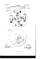
- Figure 1 is a front edge View of a mill representing the preferred embodiment of my improvement, the stones being mounted upon adjustable crank-axles and the pan being shown in sect-ion.
- Fig. 2 is a topl plan view of the same, the vertical operatingshaft being shown in section.
- Fig. 3 is a detail top elevation of a modified arrangement for adjustably connecting the crank-axles to the operating-shaft.
- Fig. 4 is a detail edge view of the same.
- Figs. 5, 6,andl7 are detail views of a further modification showing simple axles pivoted to the boxing and having set-screws for adjusting their position.
- Figs. 8 and 9 are detail top and side elevations of another form of my improvements in which the axles Figs. 10, 11, 12,
- Fig. 14 is a diagrammatic representation of a mill employing four stones, to which my improvement can also be applied.
- Fig. l5 is adiagrammaticview illustrating the action of my improved mill.
- Fig. 16 is a detail sectional view taken on the line 16 16 of Fig. 2.
- a A are the vertical millstones operating, as usual, in the pan A', and B B are adjustable crankaxles,having the innerjournal ends b b, which are mounted in adjustable boxes, presently to be described, and the outer journal ends b b', upon Whichrthe millstones A A are mounted, as shown.
- Cis the central vertical operatingshaft mounted in suitable bearings and driven by suitable gearing.
- D is a cross-beam keyed to the shaft C and formed with curved portions d d, extending, respectively, from points near the center of the opposite edges of the beam to the outer ends thereof. The ends of the beam D are formed With horizontal cross cuts or slots for the reception of the adjustable journal-boxes.
- E E are the adjustable journal-boxes, in which the inner journal ends b b of the crank-axles are journaled. These boxes t in the cross-cuts of the beam D and are formed with upper and lower curved flanges e e', which bear against the curved portions d d of the cross-beam.
- Suitable bolts F F extend from the curved faces of the crossbeam and pass through slots ff in the curved flanges e e of the boxes E E', and are held It is obvious that by loosening the nuts F F the boxes E E', carrying with them the crank-axles, can be adjusted on the curved faces of the crossbeam so as to change the inclination of the outer bearing ends b b of the crank-axles B B to the radius and tangent of the circle of revolution.
- C is the vertical operating-shaft.
- G is the cross-beam keyed to the shaft C
- H II are crank-axles adjustably connected to the opposite ends of the crossbeam G.
- J J are journal-boxes having iat grooved under facesj j,which rest on the upper face of the cross-beam G near its opposite ends and are adapted to slide thereon.
- the inner journal ends h and h of the crankaxles H H are journaled in the boxes J J and retained therein by linchpins K.
- g g are vertical longitudinal slots arranged cen- 'trally inthe ends of the cross-bar G, and
- crank-axles are set-screws passing through said slots and engaging screw-threaded openings in the under sides of the journal-boxes J J.
- the crank-axles may be adj usted longitudinally on the cross-beam G, Which changes the angle of inclination of the outer axle ends h h of the crank-axles (upon which the millstones are journaled) to the radius and tangent of the circle of revolution, as in the preferred form of my improvement.
- Fig. 5, 6, and 7, C is the central vertical operating-shaft, to which is keyed an oblong boxing L, having flaring mouths or socketsl Z at its opposite ends, in which the enlarged ends m m of the axles M M are horizontally pivoted by means of pivot-pins rm m.
- N N and N N are set-screws operatingin the side walls of the mouths or socketsl Z at the opposite ends of the boxing L and adapted to engage the enlarged ends m m of the axles for regulating the angle of inclination of the axle with relation to the radius of revolution.
- FIGs. 8 and 9 I have shown a somewhat simpler arrangement, in Which lthe millstone axles are also adjustably pivoted to their boxing.
- C is the vertical operating-shaft
- O is the boxing keyed to the shaft.
- the boxing is formed with projecting shoulders o o and slots 0 o in the ends and shoulders.
- the axles P are formed With right-angled extensions 19 p, and are pivoted at Q Q in the slotted ends of the boxing O, so that the extensions p p will normally rest inthe slots of the shoulders 0 o.
- R R are screw-bolts passing through corresponding perforations in the shoulders o o and projections p p, by means offwhich the axles can be adjusted on their pivots.
- the cross-beam S is formed with oppositely-extending flat faces, to which the enlarged ends tt of the axles T are secured by means of bolts s s, passing through perforations in both of them.
- Plates T T are placed between the ends of the axles and cross-beam to regulate the angle of inclination of the axles, a change in the thickness of the plates changing the inclinations.
- the cross-beam U is keyed to the operating-shaft C and formed with longitudinal ridges u et.
- the axles V V are formed With enlargedA ends 'v e, having longitudinal grooves n e', corresponding to and fitting over the ridges u u of the cross-beam.
- the adjacent faces of the cross-beam U and axle ends e t: are serrated, as shown, so as to more intimately engage each other.
- U U are screw-bolts projecting from the opposite faces of the cross-beam and passing through corresponding slots in the ends of the enlarged axle ends o u and held in any adjusted position therein by the nuts uu.
- Fig. 14 I have shown my improvements applied to a mill employing four millstones.
- Each axle can be adj ustably supported on the boxing in any suitable manner, such as shown.
- the axles are shown with enlarged ends adj ustably connected to the boxing by means of set-screws.
- Fig. 15 represents the action of the form of mill shown in Figs. l and 2. in position of the axles B is indicated by dotted lines.
- the lines l 4L indicate the radial changes in the position of the millstones, and the lines 2 2 represent the tangential change in the direction in which the resistance on the working-faces of the stones is exerted.
- the stone A when otherwise uninfluenced tends to move at right angles to the journal end b of the axle, as indicated by the arrow 3, and as the line of direction constantly gets nearer to the center of rotation until it crosses the radius 4, which is parallel to the journal end b', it isclear that the stone alone has an inward tendency, which is increased by the direction of the resistance.
Landscapes
- Engineering & Computer Science (AREA)
- Food Science & Technology (AREA)
- Road Repair (AREA)
Description
(No Model.) 4 Sheets-Sheet 1.
j H. MANTEY. EDGE RUNNER QR VERTICAL MILLSTONR. No. 487,930. Patented Deo. 13,1892.
ma mams creas cq, wom-mao.. WASHINGTON, n. c.
(No Model.) 4 sheets-sheet 2,
, H. MANTEY.
EDGE RUNNER 0R VERTICAL MILLSTONE.
PatientedrDeo. 13, 1892.
TH: Nonms PEfEns co.. Hoaumm wAsmNmoN. DA c.
(N0 Model.)
4 Sheets-Sheet 3. H. MANT'EY.y Y EDGE RUNNER 0R VERTIGAL MILLSTONE.
N o. 487,930. Patented Dec. 13, 18972.
ys. l
(No Model.) 4 Sheets- Sheet 4.
H. MANTEY. EDGE RUNNER OR VERTICAL MILLSTONE.
No. 487,930. Patented Dec. 13, 1892.
TN: Ncnnls Pneus pc.. PHomLlTHo.. wAsHmsToN. D. c.
UNITED STATES PATENT OFFICE.
HENRY MANTEY, OF ORIZABA, MEXICO.
vEDGE-RUNNER OR VERTICAL lVllLLSTON/E. i
SPECIFICATION forming part of Letters Patent No. 487,930, dated December 13, 1892.
Application filed September 8, 1892. Serial No. 445,323. (No model.) Iatented in Belgium PebruarylZ. 1890, No. 89,496 in France February 12,1890, No. 203,838'. in Mexico August 7, 1890, and in Germany December 24, 1890, No. 58,110.
Toa/ZZ whom it may concern:
Be it known that I, HENRY MANTEY, a citizen of the United States, residing in the city of Orizaba, in the State of Vera Cruz, Mexico, have invented a new and useful Improvement in Edge-Runners or Vertical Mill- Stones, (for which I have obtained Letters Patent in Belgiu m, No. 89,496, dated February 12, 1890; in Mexico, dated August 7, 1890; in France, No. 203,888, dated February 12, 1890, and in Germany, No. 58,110, dated December 24., 1890,) of which the following specication, taken in connection with the accompanying drawings, is a full, clear, and exact description, such as will enable those skilled in the art to make and use the same.
My invention relates to an improvement upon the millstones described and claimed in my allowed application, Serial No. 417,196, led January 6, 1892,in which the millstones are mounted upon axles arranged in the same horizontal plane of rotation, but in different vertical planes, which vertical planes are forwardly inclined with relation to the radius of rotation and do not pass through or cut the central vertical operating-shaft. The object of this arrangement is to obviate the tendency of the millstones to press outwardly on their bearings under the iniuence of the centrifugal force, and thereby to obtain a decrease in the wear of the axles and bearings.
The action of my improved mill, described in my above-named application, may be explained as follows: The resistance on the working faces of all cylindrical vertical millstones is exerted in a direction parallel with the tangent of the circle of revolution, and
the stones tend to move in the same direction. In the common form of vertical' millstones the axles upon which the stones are mounted extend radially from the vertical operatingshaft, and consequently the resistance on the working faces of the stones is exerted at right angles to their axles, and the tangential tendency of the stones, which moves them outwardly on their axles, is not counteracted. Therefore with this form of mill the centrifugal force which results from the rapid revolution of the millstones is materially aided by the outward tendency of the stones, caused by the friction on their working-faces, and it tends to throw the stones outwardly on their bearings with great forceand causes a great deal of wear. In my improved form of mill, however, the supporting-axles do not extend radially from the vertical operating-shaft, butare supported therefrom by a suitable boxing in such relation that they will be inclined to the radius and tangent of the circle of revolution, so that the resistance on the working faces of the stones (which is always in a direction parallel to the said tangent) will give them an inward tendency on their axles and counteract their outward tendency from the centrifugal force.
In the operation of this style of millstones it is obvious that the centrifugal force varies with the rate of speed atwhich the mill is run, and therefore it is very desirable to be able to adj ust the inclination of the axles to the tangent of the circle of revolution to correspond with the rate of speed, and itis the object of my present invention to provide means for accomplishing this result.
To this end my invention consists, broadly, in providing means for regulating the angle of inclination of the axles to the radius or tangent ot' the circle of revolution.
In order that my invention may be fully understood, I- will iirst describe the same with reference to the accompanying drawings, and then more particularly point out in the claims what I deem as new therein.
In the drawings, Figure 1 is a front edge View of a mill representing the preferred embodiment of my improvement, the stones being mounted upon adjustable crank-axles and the pan being shown in sect-ion. Fig. 2 is a topl plan view of the same, the vertical operatingshaft being shown in section. Fig. 3 is a detail top elevation of a modified arrangement for adjustably connecting the crank-axles to the operating-shaft. Fig. 4 is a detail edge view of the same. Figs. 5, 6,andl7 are detail views of a further modification showing simple axles pivoted to the boxing and having set-screws for adjusting their position. Figs. 8 and 9 are detail top and side elevations of another form of my improvements in which the axles Figs. 10, 11, 12,
are pivoted to the boxing.
IOO
therein by the nuts F F.
and 13 are detail top and side elevations of further modifications. Fig. 14 is a diagrammatic representation of a mill employing four stones, to which my improvement can also be applied. Fig. l5 is adiagrammaticview illustrating the action of my improved mill. Fig. 16 is a detail sectional view taken on the line 16 16 of Fig. 2.
In Figs. 1.and2, which represent the preferred embodiment of my invention, A A are the vertical millstones operating, as usual, in the pan A', and B B are adjustable crankaxles,having the innerjournal ends b b, which are mounted in adjustable boxes, presently to be described, and the outer journal ends b b', upon Whichrthe millstones A A are mounted, as shown. Cis the central vertical operatingshaft mounted in suitable bearings and driven by suitable gearing. D is a cross-beam keyed to the shaft C and formed with curved portions d d, extending, respectively, from points near the center of the opposite edges of the beam to the outer ends thereof. The ends of the beam D are formed With horizontal cross cuts or slots for the reception of the adjustable journal-boxes. E E are the adjustable journal-boxes, in which the inner journal ends b b of the crank-axles are journaled. These boxes t in the cross-cuts of the beam D and are formed with upper and lower curved flanges e e', Which bear against the curved portions d d of the cross-beam. Suitable bolts F F extend from the curved faces of the crossbeam and pass through slots ff in the curved flanges e e of the boxes E E', and are held It is obvious that by loosening the nuts F F the boxes E E', carrying with them the crank-axles, can be adjusted on the curved faces of the crossbeam so as to change the inclination of the outer bearing ends b b of the crank-axles B B to the radius and tangent of the circle of revolution.
In Figs. 3 and 4, C is the vertical operating-shaft. G is the cross-beam keyed to the shaft C, and H II are crank-axles adjustably connected to the opposite ends of the crossbeam G. J J are journal-boxes having iat grooved under facesj j,which rest on the upper face of the cross-beam G near its opposite ends and are adapted to slide thereon. The inner journal ends h and h of the crankaxles H H are journaled in the boxes J J and retained therein by linchpins K. g g are vertical longitudinal slots arranged cen- 'trally inthe ends of the cross-bar G, and
g g are set-screws passing through said slots and engaging screw-threaded openings in the under sides of the journal-boxes J J. By unscrewing the set-screws the boxes J J, carrying With them the crank-axles, may be adj usted longitudinally on the cross-beam G, Which changes the angle of inclination of the outer axle ends h h of the crank-axles (upon which the millstones are journaled) to the radius and tangent of the circle of revolution, as in the preferred form of my improvement.
In Fig. 5, 6, and 7, C is the central vertical operating-shaft, to which is keyed an oblong boxing L, having flaring mouths or socketsl Z at its opposite ends, in which the enlarged ends m m of the axles M M are horizontally pivoted by means of pivot-pins rm m. N N and N N are set-screws operatingin the side walls of the mouths or socketsl Z at the opposite ends of the boxing L and adapted to engage the enlarged ends m m of the axles for regulating the angle of inclination of the axle with relation to the radius of revolution. By respectively unscreWing and screwing up the set-screws at the opposite sides of the' socketsl Z it is obvious-that the axles will be moved on the pivots 'rn'm and their position changed.
In Figs. 8 and 9 I have shown a somewhat simpler arrangement, in Which lthe millstone axles are also adjustably pivoted to their boxing. C is the vertical operating-shaft, and O is the boxing keyed to the shaft. The boxing is formed with projecting shoulders o o and slots 0 o in the ends and shoulders. The axles P are formed With right-angled extensions 19 p, and are pivoted at Q Q in the slotted ends of the boxing O, so that the extensions p p will normally rest inthe slots of the shoulders 0 o. R R are screw-bolts passing through corresponding perforations in the shoulders o o and projections p p, by means offwhich the axles can be adjusted on their pivots.
In Figs. 10 and 1l the cross-beam S is formed with oppositely-extending flat faces, to which the enlarged ends tt of the axles T are secured by means of bolts s s, passing through perforations in both of them. Plates T T are placed between the ends of the axles and cross-beam to regulate the angle of inclination of the axles, a change in the thickness of the plates changing the inclinations.
In Figs. 12 and 13 the cross-beam U is keyed to the operating-shaft C and formed with longitudinal ridges u et. The axles V V are formed With enlargedA ends 'v e, having longitudinal grooves n e', corresponding to and fitting over the ridges u u of the cross-beam. The adjacent faces of the cross-beam U and axle ends e t: are serrated, as shown, so as to more intimately engage each other. U U are screw-bolts projecting from the opposite faces of the cross-beam and passing through corresponding slots in the ends of the enlarged axle ends o u and held in any adjusted position therein by the nuts uu. By loosening the screw-nuts u u and moving the axles on the cross-beam it is clear that the inclination of the axles with relation to the radius of revolution can be regulated.
In Fig. 14 I have shown my improvements applied to a mill employing four millstones. Each axle can be adj ustably supported on the boxing in any suitable manner, such as shown. The axles are shown with enlarged ends adj ustably connected to the boxing by means of set-screws.
IOO
IIO
It is quite obvious that my invention would apply equally as well to that form of vertical mill in which the stones are rotatively supported on a suitable axle, which is held in iixed bearings, and the pan is made to revolve under the stones. This is of course an equivalent arrangement, and the action of the stones is substantially the same.
Fig. 15 represents the action of the form of mill shown in Figs. l and 2. in position of the axles B is indicated by dotted lines. The lines l 4L indicate the radial changes in the position of the millstones, and the lines 2 2 represent the tangential change in the direction in which the resistance on the working-faces of the stones is exerted. The stone A when otherwise uninfluenced tends to move at right angles to the journal end b of the axle, as indicated by the arrow 3, and as the line of direction constantly gets nearer to the center of rotation until it crosses the radius 4, which is parallel to the journal end b', it isclear that the stone alone has an inward tendency, which is increased by the direction of the resistance.
The operation haslalready been explained, and will be clear from the above description. It is obvious that the position Aof the axles can be adjusted to such a nicety that they will exactly counteract the centrifugal force at whatever the speed it is desired to run the machine. Of course each adjusted position of the axles will only serve to counteract the centrifugal force up to a certain rate of speed.
Having thus described my invention, the following is what l claim as new therein and desire to secure by Letters Patent:
l. The combination of the vertical millstones, the axle or axles upon which said millstones are journaled, means for revolving said millstones around a common center, and means for adjusting the angle of inclination of the axles to the radius of the circle of rotation, substantially as set forth.
2. The combination of the central operat- The change ing-shaft, the cross-beam or boxing keyed to said shaft, axles adjustably secured to said cross-beam or boxing, and vertical millstones mounted on said axles, whereby the angle of inclination of the axles with relation to the radius of revolution can be adj usted, substantially as set forth. Y
3. The combination of the' vertical millstones, the crank-axles upon which the stones are journaled, the vertical operating-shaft, a cross-beam or boxing secured to the shaft, and journal-boxes in which the inner journal` ends of the crank-axles are j ournalcd, adj ustably secured to the cross-beam or boxing, whereby theangle of inclination of the axles can be adjusted with relation to the radius 'of revolution, as set forth.
4. The: combination of the vertical shaft, the cross-beam or boxing keyed to said shaft and having curved'faces or edges, journalboxes having curved faces fitting against the curved faces of the cross-beam and adj ustably secured thereto, and crank-axles having inner and outer journal ends, the inner journal ends being journaled in the adjustable boxes and the outer journal ends supporting`- the millstones, substantially 4as and for the purpose set forth.V j
5. The combination of the vertical shaft, the cross-beam or boxing keyed to said shaft and having the opposite faces or edges curved and the endsY horizontally slotted, journalboxes fitting against the slotted f ends of the cross-beam and having curved anges which tit against the curved portions of the crossbeaxn, screw-bolts projecting from the curved faces of the cross-beam and engaging'slots in the curved flanges of the journal-boxes, crankaxles journaled in the adjustable boxes, and millstones mounted on thecrank-axles, sub- 85 stantially as herein set forth.
HENRY MANTEY.
Witness es GEORGE E. AMES, WILSON B. PENNooK.
Publications (1)
| Publication Number | Publication Date |
|---|---|
| US487930A true US487930A (en) | 1892-12-13 |
Family
ID=2556777
Family Applications (1)
| Application Number | Title | Priority Date | Filing Date |
|---|---|---|---|
| US487930D Expired - Lifetime US487930A (en) | Edge-runner or vertical millstone |
Country Status (1)
| Country | Link |
|---|---|
| US (1) | US487930A (en) |
-
0
- US US487930D patent/US487930A/en not_active Expired - Lifetime
Similar Documents
| Publication | Publication Date | Title |
|---|---|---|
| US577985A (en) | Paper-cutting machine | |
| US889555A (en) | Grinding-machine. | |
| US1233514A (en) | Shredding-machine for paper-stock. | |
| US876765A (en) | Centrifugal mill. | |
| US1306772A (en) | Redtjcrbtgr-machiwe | |
| US323908A (en) | Walfeid buekmak | |
| US739492A (en) | Grinding-mill. | |
| US116033A (en) | Improvement in straw-cutters | |
| US203364A (en) | Improvement in crushing and grinding rolls | |
| US557886A (en) | Disintegrating-machine | |
| US352536A (en) | Good ale | |
| US538697A (en) | Grin ding-mill | |
| US447674A (en) | Samuel b | |
| US328413A (en) | William krutzsch | |
| US385342A (en) | Clay-pulverizer | |
| US453859A (en) | Fruit slicer or cutter | |
| US175306A (en) | Improvement in grinding and grist mills | |
| US181914A (en) | Improvement in cocoa-nut graters | |
| US308138A (en) | olawson | |
| US114303A (en) | Improvement in machines for crushing and grinding rock phosphates | |
| US249206A (en) | Machine for making oatmeal | |
| US234397A (en) | Ice-cutting machine | |
| US4378A (en) | of lockport | |
| US118636A (en) | Improvement in straw-cutters | |
| US366186A (en) | Necticut |