US4876443A - Photocell, having inclined plate cathode - Google Patents
Photocell, having inclined plate cathode Download PDFInfo
- Publication number
- US4876443A US4876443A US07/193,962 US19396288A US4876443A US 4876443 A US4876443 A US 4876443A US 19396288 A US19396288 A US 19396288A US 4876443 A US4876443 A US 4876443A
- Authority
- US
- United States
- Prior art keywords
- lines
- lead
- cathode
- anode
- photocell
- Prior art date
- Legal status (The legal status is an assumption and is not a legal conclusion. Google has not performed a legal analysis and makes no representation as to the accuracy of the status listed.)
- Expired - Fee Related
Links
- 230000005855 radiation Effects 0.000 claims abstract description 27
- 239000002184 metal Substances 0.000 claims abstract description 17
- 239000011521 glass Substances 0.000 claims abstract description 15
- 238000004519 manufacturing process Methods 0.000 claims abstract description 7
- 238000000137 annealing Methods 0.000 claims 2
- 238000007789 sealing Methods 0.000 claims 1
- 230000035945 sensitivity Effects 0.000 description 20
- 230000004043 responsiveness Effects 0.000 description 11
- 238000010586 diagram Methods 0.000 description 7
- 238000010521 absorption reaction Methods 0.000 description 3
- 230000000694 effects Effects 0.000 description 3
- 238000000034 method Methods 0.000 description 2
- 230000003595 spectral effect Effects 0.000 description 2
- 238000003466 welding Methods 0.000 description 2
- 238000004140 cleaning Methods 0.000 description 1
- 238000010276 construction Methods 0.000 description 1
- 238000011161 development Methods 0.000 description 1
- 230000018109 developmental process Effects 0.000 description 1
- 238000009826 distribution Methods 0.000 description 1
- 230000001771 impaired effect Effects 0.000 description 1
- 230000006698 induction Effects 0.000 description 1
- 238000001259 photo etching Methods 0.000 description 1
- 238000005498 polishing Methods 0.000 description 1
- 238000007517 polishing process Methods 0.000 description 1
- 238000010791 quenching Methods 0.000 description 1
- 230000000171 quenching effect Effects 0.000 description 1
Images


Classifications
-
- H—ELECTRICITY
- H01—ELECTRIC ELEMENTS
- H01J—ELECTRIC DISCHARGE TUBES OR DISCHARGE LAMPS
- H01J40/00—Photoelectric discharge tubes not involving the ionisation of a gas
- H01J40/16—Photoelectric discharge tubes not involving the ionisation of a gas having photo- emissive cathode, e.g. alkaline photoelectric cell
-
- H—ELECTRICITY
- H01—ELECTRIC ELEMENTS
- H01J—ELECTRIC DISCHARGE TUBES OR DISCHARGE LAMPS
- H01J40/00—Photoelectric discharge tubes not involving the ionisation of a gas
- H01J40/02—Details
- H01J40/04—Electrodes
Definitions
- This invention relates to a photocell, in particular for detecting U.V. radiation, comprising a plate cathode, an anode and lead-in lines extending to the plate cathode as well as lead-off lines extending from the anode, which are sealed in a glass envelope.
- a photocell constitutes a photoelectric structural element and more specifically an electron tube in which the electrons are freed from the photocathode by irradiation and then are absorbed by the oppositely disposed anode. We discriminate between vacuum photocells and gas photocells.
- the photocurrent is proportional to the luminuous intensity of the irradiated light, based on the photocathode, further to the size of the effective surfacial area of the photocathode, while at the same time a constant luminuous intensity of the same is presupposed.
- An example of the application of such a photocell is e.g. such one for detecting flames or fire, respectively. If it is desired to detect U.V. radiation, then it is self-evident that the glass of the envelope of the photocell must be permeable to such radiation.
- the electrode construction with respect to its fabrication is connected with particular effort and expenditure because of the necessary lengthy and costly working processes, since, for one thing, the plate anode must become a fine screen in a complicated photo-etching procedure, whereupon an individual polishing of either electrode must take place, while, for another thing, a complete utilization of the surface of the cathode presupposes an exact plane parallelism between the cathode and the anode, i.e. for practical utilization of the active surface of the cathode the parallelism must be secured in two coordinates.
- the profitableness and marketability of this known photocell are naturally impaired.
- the problem underlying the present invention is seen in providing a photocell of the type mentioned in the first paragraph hereinabove, which ensures a good sensitivity in conjunction with an acceptable expenditure.
- the plate cathode consists of a sheet metal strip which, at its ends, is connected to said lead-in lines, while said anode consists of a wire electrode which, at its ends, is connected to said lead-off lines and which is arranged on the plate cathode side facing the radiation to be detected, substantially parallel to said plate cathode and spaced apart a distance from the latter.
- this invention combines the efficiency-based advantage of a plate cathode with the production technical and profitableness-based advantages of a wire anode, while in this connection it has turned out that the loss of sensitivity of the photocell according to the present invention as compared with that comprising a plate anode is less than it ought to be expected.
- the wire anode does only little impair the incidence of radiation perpendicular to the plate cathode so that practically the entire surface of the plate cathode is available for the irradiation.
- the smaller absorption effect of the wire anode as against that of a plate anode does obviously run short.
- a particular advantage of the photocell according to the present invention resides in that this photocell has a good sensitivity within a wide range of different angles of incidence of the radiation, which sensitivity is only little lessened and remains also when the incident radiation is perpendicular to the plate cathode although in the case of such an angle of incidence perpendicular to the plate plane the wire anode disposed on the plate cathode side facing the radiation to be detected is causing a shading which, however, is negligible. Yet this effect is by far not comparable to that in the case of a plate anode wherein in the case of a radiation incidence perpendicular to the plate cathode this cathode is shaded to about 50%.
- both the plate cathode and the wire anode can be conjointly polished in a single electrode polishing process which, too, enhances the profitability.
- FIG. 1 shows a first practical embodiment of the photocell in a schematic view
- FIG. 2 shows the responsiveness and sensitivity respectively of the embodiment according to FIG. 1 in a longitudinal center plane containing the wire anode perpendicular to the plate cathode,
- FIG. 3 shows the responsiveness and sensitivity respectively of the embodiment according to FIG. 1 in a longitudinal center plane perpendicular to the plane according to FIG. 2,
- FIG. 4 shows a second embodiment of the photocell in a schematic view
- FIG. 5 shows a diagram corresponding to FIG. 2 with respect to the responsiveness and sensitivity respectively of the embodiment according to FIG. 4,
- FIG. 6 shows a diagram corresponding to FIG. 3 with respect to the responsiveness and sensitivity respectively of the embodiment according to FIG. 4,
- FIG. 7 shows a third embodiment of the photocell in a schematic view
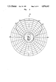
- FIG. 8 shows a top plan view of the embodiment according to FIG. 7 in a diagram showing the responsiveness and sensitivity respectively in a horizontal plane intersecting the plate cathode
- FIG. 9 shows a side view of the embodiment according to FIG. 7 and a surrounding diagram corresponding to FIGS. 3 and 6, and
- FIG. 10 shows a diagram showing the relative spectral sensitivity of the embodiment according to FIG. 7.
- the photocell according to FIG. 1 comprises a plate cathode 1, an anode 2 and lead-in lines 3 and 4 extending to the plate cathode 1 as well as lead-off lines 5 and 6 extending from the anode 2, which are sealed in a glass envelope 7 and more specifically with heat-sealed feet 8 in the thickened base 9 of the glass envelope 7 through which the contact pins 10 are brought out as electrode connections; merely three such pins 10 protruding from the underside of said base 9 downwards are shown in the schematic view of FIG. 1.
- the plate cathode 1 according to the present invention consists of a sheet metal strip 13 which, at its ends, is connected to the lead-in lines 3 and 4.
- the anode 2 consists of a wire electrode 16 which, at its ends 14 and 15, is connected to said lead-off lines 5 and 6 and which is arranged on the plate cathode side facing the radiation to be detected, substantially parallel to said plate cathode 1 and spaced apart a distance d from the latter.
- the radiation to be detected is incident on the plate cathode 1 from above, hence generally in the arrow direction A.
- the lead-in lines 3, 4 and the lead-off lines 5, 6 respectively are, as shown here, heat-sealed within the base 9 of the glass envelope in a manner such that they extend substantially parallel to each other, while the plane of the sheet metal strip 13 constituting the cathode 1 is disposed parallel to said lines and its ends 11 and 12 are rectangularly bent for connection to the lead-in lines 3 and 4.
- These ends 11, 12 of the sheet metal strip 13 are each time once bent towards the base 9 of the glass envelope while the ends 17 and 18 of the lead-in lines 3 and 4 are each time once bent towards the lead-off lines 5, 6 substantially by 90°.
- Each one end 17 and 18 respectively of the lead-in lines is connected to each one respective end 11, 12 of the sheet metal strip, suitably by welding.
- FIGS. 2 and 3 The responsiveness of this embodiment is shown in FIGS. 2 and 3 and more particularly corresponding to the depicted plane of section through the photocell according to FIG. 1.
- Each plane of section will be apparent in the light of the side view of this photocell shown in the center of the diagram.
- the greatest sensitivity in the arrow direction A with a side constancy up to about 30° toward either side and an only negligible decrease up to 45° with the minima to be expected at 90°, a renewed increase between 105° and 120° and a full decrease up to about 140°.
- FIG. 3 shows the responsiveness in the case of different angles of incidence in a section perpendicular to that according to FIG. 2. It is to be noted right here that both planes of section are suitably longitudinal center planes, i.e. they contain the longitudinal axis 19 of the photocell according to FIG. 1 and accordingly, in the case of a central arrangement of the cathode as well as of the anode, they will intersect these each time in the middle.
- FIG. 7 A further, preferred practical embodiment is apparent from FIG. 7 wherein again equal members are provided with equal reference numerals. Also here the lead in lines and the lead-off lines 3, 4 and 5, 6 respectively are welded into the base 9 of the glass envelope so as to extend substantially parallel with respect to each other, whereas the plane of the sheet metal strip 13a constituting the cathode 1 is disposed obliquely to these lines while the ends 20, 21 thereof are bent in U-shape for connection to the lead-in lines 3, 4 just as in the case also of the embodiment according to FIG. 1. However, what is decisive is the apparent oblique arrangement according to the angle ⁇ between the lead-in lines 3, 4 and the ends 20 and 21.
- the ends 14a and 15a of the wire electrode 13a are in this case bent in a plane towards the lead-off lines 5, 6, which is inclined about 45° to the longitudinal axis 19 of the glass envelope 7, as is clearly shown in FIGS. 7 and 9. Due to the inclined arrangement of the electrodes, the photocell according to the embodiment shown in FIG. 7 is suited for a front radiation as well as for a side irradiation as is peculiarly clearly shown in FIG. 9.
- the vertical irradiation direction according to the arrow direction A is inclined by 45° relative to the longitudinal axis 19 of the photocell, when it is assumed that this longitudinal axis 19 is the 0°-direction of the radiation incidence.
- the 0°-direction can be defined as the front irradiation while the 90°-direction can be defined as the side irradiation.
- FIG. 8 shows the sensitivity distribution in a horizontal section with the maximum at 90°. It stands to reason that a corresponding picture would result also for a not shown vertical section wherein the sectional plane would extend vertically on the plane of the drawing of FIG. 8 as well as on the plane of the drawing of FIG. 9 and it would contain the 0°-direction.
- the inclination of the plate cathode opens the possibility to increase the area thereof by extending its boundaries towards the inner walls of the tube.
- the projection area in the direction of the longitudinal axis of the tube as well as perpendicular thereto is the same in both cases and corresponds to the area of a plate cathode arranged perpendicular to the longitudinal axis of a tube.
- the arrangement of the plate cathode in accordance with FIG. 7 means equal sensitivity for both an angle of attack of the incident radiation parallel to the longitudinal axis of the tube and an angle of attack of incident radiation perpendicular to the longitudinal axis of the tube. If the area of the plate cathode is increased as taught above, the sensitivity should not be less than the sensitivity of a plate cathode being arranged perpendicular to the longitudinal axis of the tube.
Landscapes
- Photometry And Measurement Of Optical Pulse Characteristics (AREA)
Abstract
Description
Claims (8)
Applications Claiming Priority (2)
| Application Number | Priority Date | Filing Date | Title |
|---|---|---|---|
| DE3715924 | 1987-05-13 | ||
| DE19873715924 DE3715924A1 (en) | 1987-05-13 | 1987-05-13 | PHOTOCELL, ESPECIALLY FOR DETECTING UV RADIATION |
Publications (1)
| Publication Number | Publication Date |
|---|---|
| US4876443A true US4876443A (en) | 1989-10-24 |
Family
ID=6327422
Family Applications (1)
| Application Number | Title | Priority Date | Filing Date |
|---|---|---|---|
| US07/193,962 Expired - Fee Related US4876443A (en) | 1987-05-13 | 1988-05-13 | Photocell, having inclined plate cathode |
Country Status (3)
| Country | Link |
|---|---|
| US (1) | US4876443A (en) |
| EP (1) | EP0291084B1 (en) |
| DE (2) | DE3715924A1 (en) |
Cited By (4)
| Publication number | Priority date | Publication date | Assignee | Title |
|---|---|---|---|---|
| WO2002097757A1 (en) * | 2001-06-01 | 2002-12-05 | Xcounter Ab | Flame and spark detector, automatic fire alarm and methods related thereto |
| JP2017003497A (en) * | 2015-06-12 | 2017-01-05 | 浜松ホトニクス株式会社 | Ultraviolet detector |
| CN106935474A (en) * | 2016-08-03 | 2017-07-07 | 成都青岗科技有限公司 | A kind of micro high sensitivity ultraviolet phototube |
| CN106941072A (en) * | 2016-08-03 | 2017-07-11 | 成都青岗科技有限公司 | A kind of micro high sensitivity inflates ultraviolet phototube |
Families Citing this family (2)
| Publication number | Priority date | Publication date | Assignee | Title |
|---|---|---|---|---|
| DE4125638C2 (en) * | 1991-08-02 | 1994-06-30 | Gte Licht Gmbh | Photocell, especially for the detection of UV radiation |
| DE4134810C2 (en) * | 1991-10-22 | 1994-07-28 | Gte Licht Gmbh | Photocell, especially for the detection of UV radiation |
Citations (10)
| Publication number | Priority date | Publication date | Assignee | Title |
|---|---|---|---|---|
| US2000705A (en) * | 1931-01-17 | 1935-05-07 | Westinghouse Electric & Mfg Co | Phototube |
| US2103031A (en) * | 1935-02-08 | 1937-12-21 | Gen Electric Vapor Lamp Co | Electric gaseous discharge device |
| US2237242A (en) * | 1938-01-05 | 1941-04-01 | Univ Illinois | Phototube |
| US2283413A (en) * | 1940-08-03 | 1942-05-19 | Robert J Cashman | Phototube and method of manufacture |
| US2576251A (en) * | 1950-06-29 | 1951-11-27 | Bell Telephone Labor Inc | Electrode spacer structure for electron discharge devices |
| US2604604A (en) * | 1949-07-20 | 1952-07-22 | Bendix Aviat Corp | Mount for electron discharge devices |
| GB731755A (en) * | 1953-05-05 | 1955-06-15 | Trist & Co Ltd Ronald | Improvements relating to photo-electric cells |
| US3244890A (en) * | 1963-03-22 | 1966-04-05 | Bell Telephone Labor Inc | Photosensitive broadband coupler using wave guide |
| US3636399A (en) * | 1970-10-21 | 1972-01-18 | Dean E Eastman | Rare earth chalcogenide thermionic emission cathodes |
| US3809939A (en) * | 1972-11-08 | 1974-05-07 | Varian Associates | Gridded electron tube employing cooled ceramic insulator for mounting control grid |
Family Cites Families (6)
| Publication number | Priority date | Publication date | Assignee | Title |
|---|---|---|---|---|
| FR392849A (en) * | 1907-08-01 | 1908-12-07 | Otto Max Mueller | Improvements to safety lamps for mines |
| DE573141C (en) * | 1929-05-06 | 1933-03-28 | Westinghouse Lamp Co | Especially for measuring therapeutically effective radiation, only ultraviolet-sensitive photocell |
| US2421192A (en) * | 1943-05-29 | 1947-05-27 | Rca Corp | Multicathode phototube |
| US3372279A (en) * | 1965-05-06 | 1968-03-05 | Honeywell Inc | Ultraviolet sensitive geiger-mueller type radiation detector |
| US3656019A (en) * | 1967-08-11 | 1972-04-11 | Melpar Inc | Hydrogen-filled gas detector having cathode helix supported by envelope wall |
| AT287089B (en) * | 1968-03-15 | 1971-01-11 | Philips Nv | Method for manufacturing an electrical discharge tube with a photocathode, the active component of which consists of a highly p-conductive AIII B V compound |
-
1987
- 1987-05-13 DE DE19873715924 patent/DE3715924A1/en active Granted
-
1988
- 1988-05-13 EP EP88107750A patent/EP0291084B1/en not_active Expired - Lifetime
- 1988-05-13 DE DE88107750T patent/DE3888722D1/en not_active Expired - Fee Related
- 1988-05-13 US US07/193,962 patent/US4876443A/en not_active Expired - Fee Related
Patent Citations (10)
| Publication number | Priority date | Publication date | Assignee | Title |
|---|---|---|---|---|
| US2000705A (en) * | 1931-01-17 | 1935-05-07 | Westinghouse Electric & Mfg Co | Phototube |
| US2103031A (en) * | 1935-02-08 | 1937-12-21 | Gen Electric Vapor Lamp Co | Electric gaseous discharge device |
| US2237242A (en) * | 1938-01-05 | 1941-04-01 | Univ Illinois | Phototube |
| US2283413A (en) * | 1940-08-03 | 1942-05-19 | Robert J Cashman | Phototube and method of manufacture |
| US2604604A (en) * | 1949-07-20 | 1952-07-22 | Bendix Aviat Corp | Mount for electron discharge devices |
| US2576251A (en) * | 1950-06-29 | 1951-11-27 | Bell Telephone Labor Inc | Electrode spacer structure for electron discharge devices |
| GB731755A (en) * | 1953-05-05 | 1955-06-15 | Trist & Co Ltd Ronald | Improvements relating to photo-electric cells |
| US3244890A (en) * | 1963-03-22 | 1966-04-05 | Bell Telephone Labor Inc | Photosensitive broadband coupler using wave guide |
| US3636399A (en) * | 1970-10-21 | 1972-01-18 | Dean E Eastman | Rare earth chalcogenide thermionic emission cathodes |
| US3809939A (en) * | 1972-11-08 | 1974-05-07 | Varian Associates | Gridded electron tube employing cooled ceramic insulator for mounting control grid |
Cited By (5)
| Publication number | Priority date | Publication date | Assignee | Title |
|---|---|---|---|---|
| US6700496B2 (en) | 2001-01-06 | 2004-03-02 | Xcounter Ab | Flame and spark detector, automatic fire alarm and methods related thereto |
| WO2002097757A1 (en) * | 2001-06-01 | 2002-12-05 | Xcounter Ab | Flame and spark detector, automatic fire alarm and methods related thereto |
| JP2017003497A (en) * | 2015-06-12 | 2017-01-05 | 浜松ホトニクス株式会社 | Ultraviolet detector |
| CN106935474A (en) * | 2016-08-03 | 2017-07-07 | 成都青岗科技有限公司 | A kind of micro high sensitivity ultraviolet phototube |
| CN106941072A (en) * | 2016-08-03 | 2017-07-11 | 成都青岗科技有限公司 | A kind of micro high sensitivity inflates ultraviolet phototube |
Also Published As
| Publication number | Publication date |
|---|---|
| DE3715924C2 (en) | 1989-10-19 |
| DE3888722D1 (en) | 1994-05-05 |
| EP0291084A3 (en) | 1990-01-31 |
| EP0291084B1 (en) | 1994-03-30 |
| DE3715924A1 (en) | 1988-12-01 |
| EP0291084A2 (en) | 1988-11-17 |
Similar Documents
| Publication | Publication Date | Title |
|---|---|---|
| US6930330B2 (en) | Silicon optoelectronic device and light emitting apparatus using the same | |
| US4876443A (en) | Photocell, having inclined plate cathode | |
| EP0139314B1 (en) | Picture display panel | |
| US2289978A (en) | Television picture tube screen | |
| TW201701501A (en) | Photocathode comprising a field emitter array on a germanium substrate having a boron layer | |
| EP0838844A3 (en) | Ionization chamber | |
| GB1445619A (en) | Colour cathode ray tube | |
| KR101892637B1 (en) | Solar cell panel and the window comprising the same | |
| JPS63261664A (en) | Photomultiplier | |
| JP2001291853A (en) | Semiconductor energy detecting element | |
| US4870265A (en) | Position-sensitive radiation detector | |
| GB1592571A (en) | Cathode ray tubes | |
| JP2516995B2 (en) | Photomultiplier tube | |
| EP0328079A3 (en) | Flat crt display apparatus | |
| US3223872A (en) | Color screen with electron- and lightabsorptive material separating adjacent color strips | |
| US2314648A (en) | Television transmitting and the like system | |
| US4565946A (en) | Color cathode ray tube with infrared emitting phosphor in screen | |
| CA2336032A1 (en) | Dielectrically impeded discharge lamp with a spacer | |
| US4119885A (en) | Cathode ray tube | |
| JPS5845137B2 (en) | Denshijiyuusouchi | |
| CA1053736A (en) | Display panel with aligned matrices of priming and display cells | |
| DE4125638A1 (en) | Ultraviolet emission photocell e.g. for fire warning system - has glass bulb housing with pair of plane wire electrodes having expanded section to improve emission sensitivity | |
| US20030057896A1 (en) | Tracking tube with adapted tracking structure | |
| US5118188A (en) | Illuminating arrangement for illuminating a photomultiplier in a double-beam photometer | |
| RU2089007C1 (en) | Cathode-luminescent screen |
Legal Events
| Date | Code | Title | Description |
|---|---|---|---|
| AS | Assignment |
Owner name: GTE SYLVANIA LICHT GMBH, GRAF-ZEPPELIN-STRASSE 9-1 Free format text: ASSIGNMENT OF ASSIGNORS INTEREST.;ASSIGNOR:BEUCHER, JOSEF;REEL/FRAME:004912/0987 Effective date: 19880706 Owner name: GTE SYLVANIA LICHT GMBH,GERMANY Free format text: ASSIGNMENT OF ASSIGNORS INTEREST;ASSIGNOR:BEUCHER, JOSEF;REEL/FRAME:004912/0987 Effective date: 19880706 |
|
| FEPP | Fee payment procedure |
Free format text: PAYOR NUMBER ASSIGNED (ORIGINAL EVENT CODE: ASPN); ENTITY STATUS OF PATENT OWNER: LARGE ENTITY |
|
| AS | Assignment |
Owner name: GTE PRODUCTS CORPORATION, MASSACHUSETTS Free format text: ASSIGNMENT OF ASSIGNORS INTEREST.;ASSIGNOR:GTE LICHT GMBH;REEL/FRAME:006404/0448 Effective date: 19930129 |
|
| AS | Assignment |
Owner name: GTE LICHT GMBH, GERMANY Free format text: CHANGE OF NAME;ASSIGNOR:GTE SYLVANIA LICHT GMBH;REEL/FRAME:006437/0230 Effective date: 19871217 |
|
| FPAY | Fee payment |
Year of fee payment: 4 |
|
| FPAY | Fee payment |
Year of fee payment: 8 |
|
| REMI | Maintenance fee reminder mailed | ||
| LAPS | Lapse for failure to pay maintenance fees | ||
| STCH | Information on status: patent discontinuation |
Free format text: PATENT EXPIRED DUE TO NONPAYMENT OF MAINTENANCE FEES UNDER 37 CFR 1.362 |
|
| FP | Lapsed due to failure to pay maintenance fee |
Effective date: 20011024 |