US4868856A - Multi-component flow measurement and imaging - Google Patents
Multi-component flow measurement and imaging Download PDFInfo
- Publication number
- US4868856A US4868856A US07/289,443 US28944388A US4868856A US 4868856 A US4868856 A US 4868856A US 28944388 A US28944388 A US 28944388A US 4868856 A US4868856 A US 4868856A
- Authority
- US
- United States
- Prior art keywords
- flow
- component
- scattered
- density
- photons
- Prior art date
- Legal status (The legal status is an assumption and is not a legal conclusion. Google has not performed a legal analysis and makes no representation as to the accuracy of the status listed.)
- Expired - Fee Related
Links
Images


Classifications
-
- G—PHYSICS
- G01—MEASURING; TESTING
- G01F—MEASURING VOLUME, VOLUME FLOW, MASS FLOW OR LIQUID LEVEL; METERING BY VOLUME
- G01F1/00—Measuring the volume flow or mass flow of fluid or fluent solid material wherein the fluid passes through a meter in a continuous flow
- G01F1/76—Devices for measuring mass flow of a fluid or a fluent solid material
- G01F1/86—Indirect mass flowmeters, e.g. measuring volume flow and density, temperature or pressure
-
- G—PHYSICS
- G01—MEASURING; TESTING
- G01F—MEASURING VOLUME, VOLUME FLOW, MASS FLOW OR LIQUID LEVEL; METERING BY VOLUME
- G01F1/00—Measuring the volume flow or mass flow of fluid or fluent solid material wherein the fluid passes through a meter in a continuous flow
- G01F1/704—Measuring the volume flow or mass flow of fluid or fluent solid material wherein the fluid passes through a meter in a continuous flow using marked regions or existing inhomogeneities within the fluid stream, e.g. statistically occurring variations in a fluid parameter
- G01F1/7042—Measuring the volume flow or mass flow of fluid or fluent solid material wherein the fluid passes through a meter in a continuous flow using marked regions or existing inhomogeneities within the fluid stream, e.g. statistically occurring variations in a fluid parameter using radioactive tracers
-
- G—PHYSICS
- G01—MEASURING; TESTING
- G01F—MEASURING VOLUME, VOLUME FLOW, MASS FLOW OR LIQUID LEVEL; METERING BY VOLUME
- G01F1/00—Measuring the volume flow or mass flow of fluid or fluent solid material wherein the fluid passes through a meter in a continuous flow
- G01F1/74—Devices for measuring flow of a fluid or flow of a fluent solid material in suspension in another fluid
Definitions
- This invention relates to methods of and apparatus for the imaging and measurement of multi-component systems.
- Two or three component flow measurements have become increasingly important in a variety of process and power systems, such as, downhole monitoring of oil, oil-gas, and slurry pipelines; pneumatic conveyors, desalination plants; geothermal power stations and nuclear reactors. This is because of increased demand for flow information, not only under steady operations but also under transient and fault conditions.
- An essential feature of multicomponent flow is the presence of moving internal interfaces that make theoretical predictions of flow parameters enormous more difficult than in single-component flow.
- measurement is required to provide the information for design, supporting analyses of system behaviour, and also for the control and monitoring of the industrial multi-component systems.
- neutrons Important parameters required for characterisation of a multi-component flow field are the local and the global (mean) density and velocity.
- those based on radiation transmission and scattering are attractive because they are non-intrusive, reliable and robust.
- the use of neutrons involves the adventitious activation of the flow, and of parts of the apparatus irradiated by the neutron beam. Long data collection periods, or the use of high neutron fluxes which make the system hazardous and expensive, detract from the potential usefulness of neutrons.
- X-rays generated by electronic devices suffer from beam intensity and photon energy flucutations, and normal X-ray energies have relatively low penetration through metallic pipe sections. The cumulative effect of these and other short-comings makes the use of neutrons and X-rays unattractive for industrial flow measurements.
- Gamma rays from long-lived nuclide sources are emitted at a constant rate.
- the photon energy normally, is an order of magnitude greater than for X-rays, giving them increased penetration.
- a method of measurement of the mass flow rates, and the reconstruction of the time-averaged cross-sectional distribution of the components of a multi-component flow system comprising irradiating substantially the entire flowing medium with single scattered gamma radiation photons, detecting scattered gamma photons with wide angle photon energy detectors, determining the component velocities and computing the component mass flow rates from their respective density and velocity, and providing an image of the flow cross-sectional density distribution.
- FIG. 1 shows in diagrammatic form the Compton scattering of a photon
- FIG. 2 shows a basic scattering system
- FIG. 3 shows, in diagrammatic form, the arrangement of measuring apparatus in accordance with a specific embodiment of the invention
- FIG. 4 is a block diagram showing the processing of signals from the detectors of FIG. 3,
- FIG. 5 is an overall system block diagram
- FIGS. 6-16 are graphs showing measurements obtained using the apparatus of FIG. 3, and
- FIGS. 17-19 are reconstructed images of some flow conditions.
- Compton scattering is the process that occurs when a gamma photon collides with a free or loosely bound electron in a material.
- a photon of energy Eo sets the electron in motion, and the photon is scattered with a reduced energy E ⁇ , through an angle ⁇ along a well defined path.
- the relationship between the energy of the incident gamma photon E o and that of the scattered gamma photons E.sub. ⁇ is given by: ##EQU1## where MoC 2 is the rest mass energy of an electron, which is 0.511 MeV.
- the energy transferred to the electron (T) is the difference in energy between the incoming and outgoing photon.
- Io is the intensity of the incident beam of gamma rays
- I is the intensity of the scattered beam at the angle ⁇ and distance r from scattering electron of charge e, and mass Mo
- ⁇ Eo /MoC 2
- the equations of the cross-section for the number of photons and for the energy scattered per electron and per unit solid angle in the direction ⁇ could be derived from equations (1) and (2), and are expressed as: ##EQU3## where e ⁇ ( ⁇ ) is the cross-section for the number of photons scattered per electron per unit solid angle in the direction ⁇ and e ⁇ ( ⁇ ) is the cross-section for their energy.
- the basic scattering densitometer system is as shown schematically in FIG. 2.
- It comprises a radiation source 1 with a collimator 2 to define a primary radiation beam 3, and a radiation detector 4 with a collimator 5 to define a scattered or secondary radiation beam 6 intersecting the primary beam.
- Secondary radiation (gamma radiation) is generated along the primary beam path. However, only that radiation generated at P; the point of intersection of the primary and secondary beams is detected.
- the single scatter fraction I.sub.( ⁇ ) from P reaching the detector collimator is given by: ##EQU4## where ⁇ A is the cross-sectional area of the incident beam (cm 2 ), ⁇ Z is the height of the sensitive volume defined by the scattered beam collimator focus (cm), ⁇ is the flow mean density, ⁇ p is the flow density at P, K p and K s are the absorption coefficients for the primary and secondary radiations, and the integrals are taken along the primary beam path to the point P and along the entire secondary beam path.
- the quantity of interest is the local density ⁇ p , which cannot be determined without first knowing the values of the integrals or the density at each point along the beam paths, which is both complex and tedious.
- a second radiation source emits a second prikmary beam along the same path as the first primary beam but in the opposite direction.
- a second detector measures the intensity of either one of the primary beams after it traverses the pipe 7.
- the primary beam detector gives a measurement of the first integral in equation (5).
- a second modification to this basic system is to use the Compton-scattering effect and to acquire data for all values of ⁇ simultaneously by using a wide-angle detector that is coupled to a photon energy analyser.
- the primary radiation is gamma photons with known energy
- a measurement of the energy of the scattered photon is sufficient to determine the source from which the photon originated from the primary beam, or the value of ⁇ for that photon. This is effected by removing the collimator around the secondary radiation detector.
- FIG. 3 A preferred apparatus for imaging and measuring multi-component flow is shown in FIG. 3.
- the measurement technique is based on the principle of Compton interaction of gamma photons with matter.
- Compton-scattering effect there is a unique energy versus scattering angle dependence (an intrinsic feature).
- an intrinsic feature By this feature the flux of Compton-scattered gamma photons (gammas) coming from a particular scattering location could be determined.
- the attenuation of this flux is a function of the density of the material it has traversed.
- a homogeneous, low atomic number (Z) material e.g., a homogeneous, low atomic number (Z) material
- Each pixel gives the local density of the point, (which is the centre of the pixel) in the multi-component flow crosssection under interrogation.
- the flux of gamma radiation and their energies are detected by two matched detectors (e.g. sodium iodide thalllium NaI (T1) scintillation crystals with their associated photo-multiplier tubes, (D1 and D2) that are coupled to a multichannel analyser (MCA)).
- T1 sodium iodide thalllium NaI
- D1 and D2 photo-multiplier tubes
- MCA multichannel analyser
- the time-averaged signal is in two parts: the d.c. or slowly changing component and the a.c. or rapidly changing component.
- the d.c. component gives the density (concentration) of the material traversed. It also gives an indication of the type of flow regime prevailing during the integration time.
- the a.c. component is the natural density variation, (flow noise) occurring during the counting period. This flow noise could be used to determine the component flow velocity. This may be achieved by installing two of the measurement systems separated by a known distance along the pipe.
- the signals from the upstream and downstream measurement systems may either be Fourier analysed to obtain individual flow velocity (time of flight measurement), or time cross-correlation may be performed and the postion of the peaks of the correlograms used to determine individual component velocities.
- the externally generated Compton-scattering densitometric technique has removed the long counting period drawback associated with internally scattered gamma densitometers. With a 37 GBq source, a statistical counting error of less than 5% and an integration time of a few seconds is practicable. This relatively short counting period now makes it possible to incorporate the new measurement system into any multi-component flow loop without disturbing the flow process overall system response.
- instantaneous measurement is a necessity.
- stronger sources will have to be needed, in order to use this measurement system.
- the source strength is comparable with those being used in gamma transmission densitometry, thereby limiting personnel radiation exposure to within the existing legal permissible level.
- the Compton-scattering is generated by a homogeneous low atomic number (Z) material 10, (generator) situated outside the flow pipe 7.
- Z homogeneous low atomic number
- This arrangement fixes most of the variable parameters in equation (5), it eliminates the need for the second detector; it eliminates the need for point by point determination of the local density along the primary beam, because the singly scattered photons are generated outside the pipe from known scattering positions in the scatterer (generator) and are being used in a transmission mode; it reduces data collection time, because the secondary beam is externally generated from a generator than enhances Compton-scattering; it reduces cost and time, by the removal of the second detector, and the removal of excessive beam collimation and focussing; and it makes it possible to interrogate the entire flow cross-section with the secondary beam.
- equation (5) now becomes: ##EQU5## and e is the electron density at the source of the scatter in the generator (cm -3 ) and K p is the absorption coefficient in (cm 2 ).
- C( ⁇ ) is measurable, it is the total count detected to the secondary beam from the genertor (singly scattered photons), before traversing the flow cross-section.
- I( ⁇ ) is also measurable, it is the count of the singly scattered photons detected after the secondary beam has traversed the flow cross-section.
- ⁇ m is the mixture density
- ⁇ g is the gas density
- ⁇ is the gas void fraction
- ⁇ 1 is the density of the liquid.
- a dimensionless parametewr is obtained by normalising the mixture density with respect to the density of the liquid component. ##EQU6## Since g ⁇ 1 , we assume that the photon attentuation, due to the gas voids is negligible: ##EQU7## Thus the density measurement along a given path (chord) will be conveniently described in the interval O ⁇ d ⁇ 1. Substituting ⁇ d for ⁇ in equation (6), then: ##EQU8## Since the integration is along the path length of a finite width beam, such integration produces the mean density (concentration) of the material traversed. The integration is automatically performed by the measurement system during the ocunting period.
- Time-averaging is a signal enhancement (smoothing) process, that minimises signal noise and in the process improves the signal-to-noise (S/N) ratio.
- S/N signal-to-noise
- the configuration of the measurement system enables us to have two image views.
- Each pixel (voxel) 11 in the flow cross-section under interrogation is naturally obtained by the crossing in the pipe of the stream of scattered gamma photons from the generator.
- the value of each pixel is the local density (concentration) for the centre point of the pixel.
- a set of such values in the multi-component flow mixture cross-section gives the multi-component flow mixture local densities (concentrations).
- the ART 2 is an additive algorithm, where A represents the reconstruction matrix of point values of ⁇ and A is an auxiliary estimator.
- R q ray/sum computed from the reconstruction for ray k at angle ⁇ , q th iteration.
- N number of points contained in k th ray at angle ⁇ .
- X k ( ⁇ ) ray k mean free path.
- the individual component mass flow rates could be computed from their obtained density and velocity values.
- FIG. 3 The experimental arrangement is shown schematically in FIG. 3.
- FIG. 4 The block diagram representation of the system is shown in FIG. 4.
- the system consists of a pair of 1.85 GB1 137 Cs radionuclide sources S1 and S2 emitting radiation from within lead shielding through the slots.
- An external scatterer (Compton photon generator) is disposed between these slots.
- the rod is approximately 146 mm long and each slot is approximtely 8 mm in diameter.
- the system also includes a pair of wide-angled photon energy detectors 12, 13 (NAI (T1) detectors) and arranged to receive through slots in the lead shields, 14, 15 singly-scattered gamma photons.
- NAI wide-angled photon energy detectors 12, 13
- the flow pipe whose contents are to be interrogated, is positioned at right angles to and at a distance from the Compton photo generator so that the secondary beam photons traverse the flow pipe cross-section.
- the two gamma sources produce streams of scattered photons from the generator (secondary beam). These streams intersect each other in the flow section.
- a given small area in the flow section is interrogated by two crossing beams of photons, each with known mean energy (E ⁇ , 1). This small area is termed a pixel.
- the two beams enter their respective detectors 12, 13.
- gamma radiation from two twin sources S 11 ,S 12 ,S 21 ,S 22 is directed on to respective Compton scatterers C1,C2 spaced apart by a predetermined distance L.
- Scattered radiation therefrom irradiates the entire cross-section of a flow pipe F. Radiation further scattered by material flowing down the pipe is detected at different angles by detectors D11,D12,D21,D22, the outputs of which are fed by way of pre-amplifiers PA11,PA12,PA21,PA22, amplifiers A11,A12,A21,A22 and mixer-router MR to an analog/digital converter A.D.C. and multi-channel analyser M.C.A. to a computer C.
- Correlators C01,C02 also provide inputs to the computer from the detectors. After data analysis, involving an appropriate image reconstruction algorithm, an image of the time-averaged density distribution of the flow cross-section, (e.g. FIGS. 17-19) and the flow component concentrations (e.g. FIGS. 7-16) can be obtained.
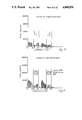
- the measurement system confines the singly-scattered photon energies due to 137 Cs to the range 250-450 KeV. Scattered photons (from a 137 Cs source) in this energy range are predominantly singly-scattered, thereby minimising multiple scattering contribution.
- FIG. 6 A typical spectrum of Compton-scattered photons is shown in FIG. 6. The singly-scattered photons are within the marked region, and the change in spectrum of this marked region is directly related to the density of the material the photons have traversed.
- FIGS. 7-10 are the result of tests carried out to investigate the uniformity of the scattered photons using a triangular aluminum section. These results show that having two similar sources, one each side of the scatterer, a relatively uniform field of singly-scattered photons is generated.
- FIGS. 11-12 are the results obtained from stationary materials to simulate known flow conditions.
- FIGS. 13-16 are the results obtained from water/air flow conditions in a static mode.
- FIGS. 17-19 are reconstructed images for some of the flow conditions shown in FIGS. 13-16.
Landscapes
- Physics & Mathematics (AREA)
- Fluid Mechanics (AREA)
- General Physics & Mathematics (AREA)
- Analysing Materials By The Use Of Radiation (AREA)
- Measurement Of Radiation (AREA)
Applications Claiming Priority (2)
| Application Number | Priority Date | Filing Date | Title |
|---|---|---|---|
| GB8521287 | 1985-08-27 | ||
| GB858521287A GB8521287D0 (en) | 1985-08-27 | 1985-08-27 | Flow measurement & imaging |
Publications (1)
| Publication Number | Publication Date |
|---|---|
| US4868856A true US4868856A (en) | 1989-09-19 |
Family
ID=10584318
Family Applications (1)
| Application Number | Title | Priority Date | Filing Date |
|---|---|---|---|
| US07/289,443 Expired - Fee Related US4868856A (en) | 1985-08-27 | 1988-12-22 | Multi-component flow measurement and imaging |
Country Status (4)
| Country | Link |
|---|---|
| US (1) | US4868856A (fr) |
| EP (1) | EP0216526B1 (fr) |
| DE (1) | DE3671294D1 (fr) |
| GB (2) | GB8521287D0 (fr) |
Cited By (45)
| Publication number | Priority date | Publication date | Assignee | Title |
|---|---|---|---|---|
| US5065418A (en) * | 1989-08-09 | 1991-11-12 | Heimann Gmbh | Apparatus for the transillumination of articles with fan-shaped radiation |
| US5694933A (en) * | 1995-04-28 | 1997-12-09 | Care Wise Medical Products Corporation | Apparatus and methods for determining spatial coordinates of radiolabelled tissue using gamma-rays and associated characteristic X-rays |
| US6246159B1 (en) | 1998-09-03 | 2001-06-12 | L'etat Francais, Represente Par Le Delegue Ministeriel Pour L'armement | Piezosensitive device comprising pyrophosphate material and method of making device |
| US6324248B1 (en) * | 1999-10-07 | 2001-11-27 | U.S. Philips Corporation | Deriving a cross-sectional distribution from an object data set |
| US6335856B1 (en) | 1999-03-05 | 2002-01-01 | L'etat Francais, Represente Par Le Delegue Ministeriel Pour L'armement | Triboelectric device |
| WO2002036293A1 (fr) * | 2000-11-03 | 2002-05-10 | Mpc Metal Process Control Ab | Commande d'un flux de metal |
| WO2004097344A2 (fr) * | 2003-04-25 | 2004-11-11 | Cxr Limited | Surveillance par rayons x |
| US20060256924A1 (en) * | 2003-04-25 | 2006-11-16 | Morton Edward J | X-ray sources |
| US20070172023A1 (en) * | 2003-04-25 | 2007-07-26 | Cxr Limited | Control means for heat load in x-ray scanning apparatus |
| US20080049899A1 (en) * | 2006-08-23 | 2008-02-28 | American Science And Engineering, Inc. | Scatter Attenuation Tomography |
| US20080144774A1 (en) * | 2003-04-25 | 2008-06-19 | Crx Limited | X-Ray Tubes |
| US20080219404A1 (en) * | 2007-03-08 | 2008-09-11 | Bio-Imaging Research, Inc. | Method and Apparatus to Facilitate Formation of a Two-Dimensional Image Using X-Ray Fan Beam Scatter |
| US7512215B2 (en) | 2003-04-25 | 2009-03-31 | Rapiscan Systems, Inc. | X-ray tube electron sources |
| US20100008471A1 (en) * | 2003-04-25 | 2010-01-14 | Edward James Morton | X-Ray Sources |
| US20100034347A1 (en) * | 2006-08-23 | 2010-02-11 | American Science And Engineering, Inc. | Scatter Attenuation Tomography |
| US7684538B2 (en) | 2003-04-25 | 2010-03-23 | Rapiscan Systems, Inc. | X-ray scanning system |
| US7949101B2 (en) | 2005-12-16 | 2011-05-24 | Rapiscan Systems, Inc. | X-ray scanners and X-ray sources therefor |
| WO2011119045A1 (fr) * | 2010-03-24 | 2011-09-29 | Institutt For Energiteknikk | Procédé de réalisation de mesures par tomodensitométrie de flux multiphases contenant du pétrole à travers une conduite |
| US8135110B2 (en) | 2005-12-16 | 2012-03-13 | Rapiscan Systems, Inc. | X-ray tomography inspection systems |
| US8223919B2 (en) | 2003-04-25 | 2012-07-17 | Rapiscan Systems, Inc. | X-ray tomographic inspection systems for the identification of specific target items |
| US8243876B2 (en) | 2003-04-25 | 2012-08-14 | Rapiscan Systems, Inc. | X-ray scanners |
| US8451974B2 (en) | 2003-04-25 | 2013-05-28 | Rapiscan Systems, Inc. | X-ray tomographic inspection system for the identification of specific target items |
| US8804899B2 (en) | 2003-04-25 | 2014-08-12 | Rapiscan Systems, Inc. | Imaging, data acquisition, data transmission, and data distribution methods and systems for high data rate tomographic X-ray scanners |
| US8824637B2 (en) | 2008-09-13 | 2014-09-02 | Rapiscan Systems, Inc. | X-ray tubes |
| US8837669B2 (en) | 2003-04-25 | 2014-09-16 | Rapiscan Systems, Inc. | X-ray scanning system |
| US8842808B2 (en) | 2006-08-11 | 2014-09-23 | American Science And Engineering, Inc. | Scatter attenuation tomography using a monochromatic radiation source |
| US9052403B2 (en) | 2002-07-23 | 2015-06-09 | Rapiscan Systems, Inc. | Compact mobile cargo scanning system |
| US9113839B2 (en) | 2003-04-25 | 2015-08-25 | Rapiscon Systems, Inc. | X-ray inspection system and method |
| US9208988B2 (en) | 2005-10-25 | 2015-12-08 | Rapiscan Systems, Inc. | Graphite backscattered electron shield for use in an X-ray tube |
| US9218933B2 (en) | 2011-06-09 | 2015-12-22 | Rapidscan Systems, Inc. | Low-dose radiographic imaging system |
| US9223052B2 (en) | 2008-02-28 | 2015-12-29 | Rapiscan Systems, Inc. | Scanning systems |
| US9223049B2 (en) | 2002-07-23 | 2015-12-29 | Rapiscan Systems, Inc. | Cargo scanning system with boom structure |
| US9223050B2 (en) | 2005-04-15 | 2015-12-29 | Rapiscan Systems, Inc. | X-ray imaging system having improved mobility |
| GB2507368B (en) * | 2013-04-30 | 2016-01-06 | Iphase Ltd | Method and apparatus for monitoring the flow of mixtures of fluids in a pipe |
| US9263225B2 (en) | 2008-07-15 | 2016-02-16 | Rapiscan Systems, Inc. | X-ray tube anode comprising a coolant tube |
| US9285498B2 (en) | 2003-06-20 | 2016-03-15 | Rapiscan Systems, Inc. | Relocatable X-ray imaging system and method for inspecting commercial vehicles and cargo containers |
| US9332624B2 (en) | 2008-05-20 | 2016-05-03 | Rapiscan Systems, Inc. | Gantry scanner systems |
| US9420677B2 (en) | 2009-01-28 | 2016-08-16 | Rapiscan Systems, Inc. | X-ray tube electron sources |
| US9429530B2 (en) | 2008-02-28 | 2016-08-30 | Rapiscan Systems, Inc. | Scanning systems |
| US9726619B2 (en) | 2005-10-25 | 2017-08-08 | Rapiscan Systems, Inc. | Optimization of the source firing pattern for X-ray scanning systems |
| US9791590B2 (en) | 2013-01-31 | 2017-10-17 | Rapiscan Systems, Inc. | Portable security inspection system |
| US10483077B2 (en) | 2003-04-25 | 2019-11-19 | Rapiscan Systems, Inc. | X-ray sources having reduced electron scattering |
| US10585206B2 (en) | 2017-09-06 | 2020-03-10 | Rapiscan Systems, Inc. | Method and system for a multi-view scanner |
| US11212902B2 (en) | 2020-02-25 | 2021-12-28 | Rapiscan Systems, Inc. | Multiplexed drive systems and methods for a multi-emitter X-ray source |
| US11551903B2 (en) | 2020-06-25 | 2023-01-10 | American Science And Engineering, Inc. | Devices and methods for dissipating heat from an anode of an x-ray tube assembly |
Families Citing this family (6)
| Publication number | Priority date | Publication date | Assignee | Title |
|---|---|---|---|---|
| GB8726478D0 (en) * | 1987-11-12 | 1987-12-16 | Unilever Plc | Metering apparatus |
| AU618602B2 (en) * | 1988-06-03 | 1992-01-02 | Commonwealth Scientific And Industrial Research Organisation | Measurement of flow velocity and mass flowrate |
| GB2232241B (en) * | 1989-05-27 | 1993-06-02 | Schlumberger Ltd | Method for determining dynamic flow characteristics of multiphase flows |
| LU87594A1 (de) * | 1989-09-25 | 1991-05-07 | Euratom | Verfahren und vorrichtung zur massenstrommessung in einem kanal mit mehrphasenstroemung |
| MY123677A (en) * | 1993-04-26 | 2006-05-31 | Shell Int Research | Fluid composition meter |
| GB2562215B (en) * | 2017-05-04 | 2019-08-07 | Sensinite Oy | System and method of producing analysis data indicative of presence of known isotope in sample |
Citations (3)
| Publication number | Priority date | Publication date | Assignee | Title |
|---|---|---|---|---|
| US4228353A (en) * | 1978-05-02 | 1980-10-14 | Johnson Steven A | Multiple-phase flowmeter and materials analysis apparatus and method |
| US4282433A (en) * | 1978-04-19 | 1981-08-04 | Kernforschungszentrum Karlsruhe Gmbh | Apparatus for measuring the density of a multiphase stream |
| US4359638A (en) * | 1979-11-09 | 1982-11-16 | Zikonix Corporation | Method for continuously determining the composition of butter and similar substances from a manufacturing process |
Family Cites Families (3)
| Publication number | Priority date | Publication date | Assignee | Title |
|---|---|---|---|---|
| DK126523B (da) * | 1971-10-07 | 1973-07-23 | Isotopcentralen | Materialestrømsmåleapparat. |
| US4064440A (en) * | 1976-06-22 | 1977-12-20 | Roder Frederick L | X-ray or gamma-ray examination device for moving objects |
| US4205230A (en) * | 1977-08-29 | 1980-05-27 | Pretron Electronics Pty. Ltd. | Solid materials flow rate measurement |
-
1985
- 1985-08-27 GB GB858521287A patent/GB8521287D0/en active Pending
-
1986
- 1986-08-27 EP EP86306602A patent/EP0216526B1/fr not_active Expired
- 1986-08-27 GB GB8620721A patent/GB2180065B/en not_active Expired
- 1986-08-27 DE DE8686306602T patent/DE3671294D1/de not_active Expired - Lifetime
-
1988
- 1988-12-22 US US07/289,443 patent/US4868856A/en not_active Expired - Fee Related
Patent Citations (3)
| Publication number | Priority date | Publication date | Assignee | Title |
|---|---|---|---|---|
| US4282433A (en) * | 1978-04-19 | 1981-08-04 | Kernforschungszentrum Karlsruhe Gmbh | Apparatus for measuring the density of a multiphase stream |
| US4228353A (en) * | 1978-05-02 | 1980-10-14 | Johnson Steven A | Multiple-phase flowmeter and materials analysis apparatus and method |
| US4359638A (en) * | 1979-11-09 | 1982-11-16 | Zikonix Corporation | Method for continuously determining the composition of butter and similar substances from a manufacturing process |
Non-Patent Citations (2)
| Title |
|---|
| Gay, Rodney, Ohkawa, Katsuhiro, Conference: Instrumentation in the Aerospace Industry, vol. 26, Advancesin Test Measurement, vol. 17, Proceedings of the 26th International Instrumentation Symposium, Seattle, WA (5 8, May 1980), pp. 253 260. * |
| Gay, Rodney, Ohkawa, Katsuhiro, Conference: Instrumentation in the Aerospace Industry, vol. 26, Advancesin Test Measurement, vol. 17, Proceedings of the 26th International Instrumentation Symposium, Seattle, WA (5-8, May 1980), pp. 253-260. |
Cited By (101)
| Publication number | Priority date | Publication date | Assignee | Title |
|---|---|---|---|---|
| US5065418A (en) * | 1989-08-09 | 1991-11-12 | Heimann Gmbh | Apparatus for the transillumination of articles with fan-shaped radiation |
| US5694933A (en) * | 1995-04-28 | 1997-12-09 | Care Wise Medical Products Corporation | Apparatus and methods for determining spatial coordinates of radiolabelled tissue using gamma-rays and associated characteristic X-rays |
| US6135955A (en) * | 1995-04-28 | 2000-10-24 | Care Wise Medical Products Corporation | Apparatus and methods for determining spatial coordinates of radiolabeled tissue using gamma-rays and associated characteristic x-rays |
| US6246159B1 (en) | 1998-09-03 | 2001-06-12 | L'etat Francais, Represente Par Le Delegue Ministeriel Pour L'armement | Piezosensitive device comprising pyrophosphate material and method of making device |
| US6335856B1 (en) | 1999-03-05 | 2002-01-01 | L'etat Francais, Represente Par Le Delegue Ministeriel Pour L'armement | Triboelectric device |
| US6324248B1 (en) * | 1999-10-07 | 2001-11-27 | U.S. Philips Corporation | Deriving a cross-sectional distribution from an object data set |
| WO2002036293A1 (fr) * | 2000-11-03 | 2002-05-10 | Mpc Metal Process Control Ab | Commande d'un flux de metal |
| US20040026064A1 (en) * | 2000-11-03 | 2004-02-12 | Michel Cervantes | Metal flow control |
| KR100846250B1 (ko) | 2000-11-03 | 2008-07-16 | 엠피씨 메탈 프로세스 컨트롤 에이비 | 금속 흐름 제어 |
| US7013949B2 (en) | 2000-11-03 | 2006-03-21 | Mpc Metal Process Controll Ab | Metal flow control |
| US10670769B2 (en) | 2002-07-23 | 2020-06-02 | Rapiscan Systems, Inc. | Compact mobile cargo scanning system |
| US10007019B2 (en) | 2002-07-23 | 2018-06-26 | Rapiscan Systems, Inc. | Compact mobile cargo scanning system |
| US9223049B2 (en) | 2002-07-23 | 2015-12-29 | Rapiscan Systems, Inc. | Cargo scanning system with boom structure |
| US9052403B2 (en) | 2002-07-23 | 2015-06-09 | Rapiscan Systems, Inc. | Compact mobile cargo scanning system |
| US9675306B2 (en) | 2003-04-25 | 2017-06-13 | Rapiscan Systems, Inc. | X-ray scanning system |
| US9113839B2 (en) | 2003-04-25 | 2015-08-25 | Rapiscon Systems, Inc. | X-ray inspection system and method |
| CN100371689C (zh) * | 2003-04-25 | 2008-02-27 | Cxr有限公司 | X射线监控 |
| US11796711B2 (en) | 2003-04-25 | 2023-10-24 | Rapiscan Systems, Inc. | Modular CT scanning system |
| US7349525B2 (en) | 2003-04-25 | 2008-03-25 | Rapiscan Systems, Inc. | X-ray sources |
| US20080144774A1 (en) * | 2003-04-25 | 2008-06-19 | Crx Limited | X-Ray Tubes |
| GB2418019B (en) * | 2003-04-25 | 2007-03-14 | Cxr Ltd | X-ray monitoring |
| US10901112B2 (en) | 2003-04-25 | 2021-01-26 | Rapiscan Systems, Inc. | X-ray scanning system with stationary x-ray sources |
| US7440543B2 (en) | 2003-04-25 | 2008-10-21 | Rapiscan Systems, Inc. | X-ray monitoring |
| US20080267355A1 (en) * | 2003-04-25 | 2008-10-30 | Edward James Morton | X-Ray Sources |
| US7505563B2 (en) | 2003-04-25 | 2009-03-17 | Rapiscan Systems, Inc. | X-ray sources |
| US7512215B2 (en) | 2003-04-25 | 2009-03-31 | Rapiscan Systems, Inc. | X-ray tube electron sources |
| WO2004097344A2 (fr) * | 2003-04-25 | 2004-11-11 | Cxr Limited | Surveillance par rayons x |
| US7564939B2 (en) | 2003-04-25 | 2009-07-21 | Rapiscan Systems, Inc. | Control means for heat load in X-ray scanning apparatus |
| US20090274277A1 (en) * | 2003-04-25 | 2009-11-05 | Edward James Morton | X-Ray Sources |
| US20090316855A1 (en) * | 2003-04-25 | 2009-12-24 | Edward James Morton | Control Means for Heat Load in X-Ray Scanning Apparatus |
| US20100008471A1 (en) * | 2003-04-25 | 2010-01-14 | Edward James Morton | X-Ray Sources |
| US10591424B2 (en) | 2003-04-25 | 2020-03-17 | Rapiscan Systems, Inc. | X-ray tomographic inspection systems for the identification of specific target items |
| US7664230B2 (en) | 2003-04-25 | 2010-02-16 | Rapiscan Systems, Inc. | X-ray tubes |
| US7684538B2 (en) | 2003-04-25 | 2010-03-23 | Rapiscan Systems, Inc. | X-ray scanning system |
| US7724868B2 (en) | 2003-04-25 | 2010-05-25 | Rapiscan Systems, Inc. | X-ray monitoring |
| US20100172476A1 (en) * | 2003-04-25 | 2010-07-08 | Edward James Morton | X-Ray Tubes |
| US7903789B2 (en) | 2003-04-25 | 2011-03-08 | Rapiscan Systems, Inc. | X-ray tube electron sources |
| US10483077B2 (en) | 2003-04-25 | 2019-11-19 | Rapiscan Systems, Inc. | X-ray sources having reduced electron scattering |
| US7929663B2 (en) | 2003-04-25 | 2011-04-19 | Rapiscan Systems, Inc. | X-ray monitoring |
| US10175381B2 (en) | 2003-04-25 | 2019-01-08 | Rapiscan Systems, Inc. | X-ray scanners having source points with less than a predefined variation in brightness |
| WO2004097344A3 (fr) * | 2003-04-25 | 2005-05-12 | Cxr Ltd | Surveillance par rayons x |
| US8085897B2 (en) | 2003-04-25 | 2011-12-27 | Rapiscan Systems, Inc. | X-ray scanning system |
| US8094784B2 (en) | 2003-04-25 | 2012-01-10 | Rapiscan Systems, Inc. | X-ray sources |
| US9747705B2 (en) | 2003-04-25 | 2017-08-29 | Rapiscan Systems, Inc. | Imaging, data acquisition, data transmission, and data distribution methods and systems for high data rate tomographic X-ray scanners |
| US8223919B2 (en) | 2003-04-25 | 2012-07-17 | Rapiscan Systems, Inc. | X-ray tomographic inspection systems for the identification of specific target items |
| US8243876B2 (en) | 2003-04-25 | 2012-08-14 | Rapiscan Systems, Inc. | X-ray scanners |
| US8451974B2 (en) | 2003-04-25 | 2013-05-28 | Rapiscan Systems, Inc. | X-ray tomographic inspection system for the identification of specific target items |
| GB2418019A (en) * | 2003-04-25 | 2006-03-15 | Cxr Ltd | X-ray monitoring |
| US8804899B2 (en) | 2003-04-25 | 2014-08-12 | Rapiscan Systems, Inc. | Imaging, data acquisition, data transmission, and data distribution methods and systems for high data rate tomographic X-ray scanners |
| US9618648B2 (en) | 2003-04-25 | 2017-04-11 | Rapiscan Systems, Inc. | X-ray scanners |
| US8837669B2 (en) | 2003-04-25 | 2014-09-16 | Rapiscan Systems, Inc. | X-ray scanning system |
| US9442082B2 (en) | 2003-04-25 | 2016-09-13 | Rapiscan Systems, Inc. | X-ray inspection system and method |
| US8885794B2 (en) | 2003-04-25 | 2014-11-11 | Rapiscan Systems, Inc. | X-ray tomographic inspection system for the identification of specific target items |
| US20060203961A1 (en) * | 2003-04-25 | 2006-09-14 | Morton Edward J | X-ray monitoring |
| US9001973B2 (en) | 2003-04-25 | 2015-04-07 | Rapiscan Systems, Inc. | X-ray sources |
| US9020095B2 (en) | 2003-04-25 | 2015-04-28 | Rapiscan Systems, Inc. | X-ray scanners |
| US9183647B2 (en) | 2003-04-25 | 2015-11-10 | Rapiscan Systems, Inc. | Imaging, data acquisition, data transmission, and data distribution methods and systems for high data rate tomographic X-ray scanners |
| US20060256924A1 (en) * | 2003-04-25 | 2006-11-16 | Morton Edward J | X-ray sources |
| US20070172023A1 (en) * | 2003-04-25 | 2007-07-26 | Cxr Limited | Control means for heat load in x-ray scanning apparatus |
| US9285498B2 (en) | 2003-06-20 | 2016-03-15 | Rapiscan Systems, Inc. | Relocatable X-ray imaging system and method for inspecting commercial vehicles and cargo containers |
| US9223050B2 (en) | 2005-04-15 | 2015-12-29 | Rapiscan Systems, Inc. | X-ray imaging system having improved mobility |
| US9208988B2 (en) | 2005-10-25 | 2015-12-08 | Rapiscan Systems, Inc. | Graphite backscattered electron shield for use in an X-ray tube |
| US9726619B2 (en) | 2005-10-25 | 2017-08-08 | Rapiscan Systems, Inc. | Optimization of the source firing pattern for X-ray scanning systems |
| US9048061B2 (en) | 2005-12-16 | 2015-06-02 | Rapiscan Systems, Inc. | X-ray scanners and X-ray sources therefor |
| US8958526B2 (en) | 2005-12-16 | 2015-02-17 | Rapiscan Systems, Inc. | Data collection, processing and storage systems for X-ray tomographic images |
| US10295483B2 (en) | 2005-12-16 | 2019-05-21 | Rapiscan Systems, Inc. | Data collection, processing and storage systems for X-ray tomographic images |
| US8135110B2 (en) | 2005-12-16 | 2012-03-13 | Rapiscan Systems, Inc. | X-ray tomography inspection systems |
| US10976271B2 (en) | 2005-12-16 | 2021-04-13 | Rapiscan Systems, Inc. | Stationary tomographic X-ray imaging systems for automatically sorting objects based on generated tomographic images |
| US8625735B2 (en) | 2005-12-16 | 2014-01-07 | Rapiscan Systems, Inc. | X-ray scanners and X-ray sources therefor |
| US7949101B2 (en) | 2005-12-16 | 2011-05-24 | Rapiscan Systems, Inc. | X-ray scanners and X-ray sources therefor |
| US9638646B2 (en) | 2005-12-16 | 2017-05-02 | Rapiscan Systems, Inc. | X-ray scanners and X-ray sources therefor |
| US8842808B2 (en) | 2006-08-11 | 2014-09-23 | American Science And Engineering, Inc. | Scatter attenuation tomography using a monochromatic radiation source |
| US7551718B2 (en) * | 2006-08-23 | 2009-06-23 | American Science And Engineering, Inc. | Scatter attenuation tomography |
| US20100034347A1 (en) * | 2006-08-23 | 2010-02-11 | American Science And Engineering, Inc. | Scatter Attenuation Tomography |
| US20080049899A1 (en) * | 2006-08-23 | 2008-02-28 | American Science And Engineering, Inc. | Scatter Attenuation Tomography |
| US7924979B2 (en) | 2006-08-23 | 2011-04-12 | American Science And Engineering, Inc. | Scatter attenuation tomography |
| US20080219404A1 (en) * | 2007-03-08 | 2008-09-11 | Bio-Imaging Research, Inc. | Method and Apparatus to Facilitate Formation of a Two-Dimensional Image Using X-Ray Fan Beam Scatter |
| US9429530B2 (en) | 2008-02-28 | 2016-08-30 | Rapiscan Systems, Inc. | Scanning systems |
| US9223052B2 (en) | 2008-02-28 | 2015-12-29 | Rapiscan Systems, Inc. | Scanning systems |
| US11275194B2 (en) | 2008-02-28 | 2022-03-15 | Rapiscan Systems, Inc. | Scanning systems |
| US10585207B2 (en) | 2008-02-28 | 2020-03-10 | Rapiscan Systems, Inc. | Scanning systems |
| US11768313B2 (en) | 2008-02-28 | 2023-09-26 | Rapiscan Systems, Inc. | Multi-scanner networked systems for performing material discrimination processes on scanned objects |
| US9332624B2 (en) | 2008-05-20 | 2016-05-03 | Rapiscan Systems, Inc. | Gantry scanner systems |
| US10098214B2 (en) | 2008-05-20 | 2018-10-09 | Rapiscan Systems, Inc. | Detector support structures for gantry scanner systems |
| US9263225B2 (en) | 2008-07-15 | 2016-02-16 | Rapiscan Systems, Inc. | X-ray tube anode comprising a coolant tube |
| US8824637B2 (en) | 2008-09-13 | 2014-09-02 | Rapiscan Systems, Inc. | X-ray tubes |
| US9420677B2 (en) | 2009-01-28 | 2016-08-16 | Rapiscan Systems, Inc. | X-ray tube electron sources |
| WO2011119045A1 (fr) * | 2010-03-24 | 2011-09-29 | Institutt For Energiteknikk | Procédé de réalisation de mesures par tomodensitométrie de flux multiphases contenant du pétrole à travers une conduite |
| US9218933B2 (en) | 2011-06-09 | 2015-12-22 | Rapidscan Systems, Inc. | Low-dose radiographic imaging system |
| US9791590B2 (en) | 2013-01-31 | 2017-10-17 | Rapiscan Systems, Inc. | Portable security inspection system |
| US11550077B2 (en) | 2013-01-31 | 2023-01-10 | Rapiscan Systems, Inc. | Portable vehicle inspection portal with accompanying workstation |
| US10317566B2 (en) | 2013-01-31 | 2019-06-11 | Rapiscan Systems, Inc. | Portable security inspection system |
| GB2513678B (en) * | 2013-04-30 | 2017-02-22 | Iphase Ltd | Oil well system and operating method including monitoring multi-phase flow in a pipe |
| US10739177B2 (en) | 2013-04-30 | 2020-08-11 | Iphase Limited | Method and apparatus for monitoring the flow of mixtures of fluids in a pipe |
| US10753778B2 (en) | 2013-04-30 | 2020-08-25 | Iphase Limited | Method and apparatus for monitoring the flow of mixtures of fluids in a pipe |
| US10378941B2 (en) | 2013-04-30 | 2019-08-13 | Iphase Limited | Method and apparatus for monitoring the flow of mixtures of fluid in a pipe |
| GB2513679B (en) * | 2013-04-30 | 2016-01-06 | Iphase Ltd | Method of defining a mulitphase flow comprising three phases |
| GB2507368B (en) * | 2013-04-30 | 2016-01-06 | Iphase Ltd | Method and apparatus for monitoring the flow of mixtures of fluids in a pipe |
| US10585206B2 (en) | 2017-09-06 | 2020-03-10 | Rapiscan Systems, Inc. | Method and system for a multi-view scanner |
| US11212902B2 (en) | 2020-02-25 | 2021-12-28 | Rapiscan Systems, Inc. | Multiplexed drive systems and methods for a multi-emitter X-ray source |
| US11551903B2 (en) | 2020-06-25 | 2023-01-10 | American Science And Engineering, Inc. | Devices and methods for dissipating heat from an anode of an x-ray tube assembly |
Also Published As
| Publication number | Publication date |
|---|---|
| EP0216526A1 (fr) | 1987-04-01 |
| DE3671294D1 (de) | 1990-06-21 |
| GB8521287D0 (en) | 1985-10-02 |
| GB8620721D0 (en) | 1986-10-08 |
| GB2180065B (en) | 1989-11-29 |
| GB2180065A (en) | 1987-03-18 |
| EP0216526B1 (fr) | 1990-05-16 |
Similar Documents
| Publication | Publication Date | Title |
|---|---|---|
| US4868856A (en) | Multi-component flow measurement and imaging | |
| RU2533758C2 (ru) | Устройство и способ для измерения многофазного потока флюида | |
| Abouelwafa et al. | The measurement of component ratios in multiphase systems using alpha-ray attenuation | |
| El Abd | Intercomparison of gamma ray scattering and transmission techniques for gas volume fraction measurements in two phase pipe flow | |
| Priyada et al. | Intercomparison of gamma scattering, gammatography, and radiography techniques for mild steel nonuniform corrosion detection | |
| GB2088050A (en) | Gamma Ray Analysis of Multi- component Material | |
| Johansen | Nuclear tomography methods in industry | |
| US20150226589A1 (en) | X-Ray Based Multiphase Flow Meter with Energy Resolving Matrix Detector | |
| Osman et al. | Measurement of void fraction in pipes by nuclear transmission based techniques | |
| Shohani et al. | A new method of gamma level gauge using a position-sensitive sensor with rod plastic scintillator | |
| Åbro et al. | A radiation transport model as a design tool for gamma densitometers | |
| Falcone | Key multiphase flow metering techniques | |
| JPH06103279B2 (ja) | 成分分析方法 | |
| US4817122A (en) | Apparatus for radiation analysis | |
| US3470372A (en) | Fog density measurement by x-ray scattering | |
| US3154684A (en) | X-ray analysis system with means to detect only the coherently scattered X-rays | |
| IE903435A1 (en) | A method and a device for the mass flow measurement in a¹multiphase flow channel | |
| Salgado et al. | Study of volume fractions on biphasic stratified regime using gamma ray | |
| Salgado et al. | Volume fractions calculation of a biphasic system on cylindrical tube using gamma ray and MCNP6 code | |
| Sandtorv | Development of Monte-Carlo Simulation Model of the UiB Gamma-ray tomography system using MCNP | |
| RU2086955C1 (ru) | Способ измерения параметров газожидкостного потока | |
| Zubakin et al. | Development of an Innovational Multiphase X-Ray Flowmeter | |
| Omotosho et al. | A sensing system for non-destructive imaging using externally compton-scattered gamma photons | |
| RU154702U1 (ru) | Концентратомер многофазной жидкости | |
| RU76452U1 (ru) | Рентгеновский анализатор расхода и состава компонентов трехкомпонентного потока |
Legal Events
| Date | Code | Title | Description |
|---|---|---|---|
| AS | Assignment |
Owner name: NATIONAL RESEARCH DEVELOPMENT CORPORATION, A BRITI Free format text: ASSIGNMENT OF ASSIGNORS INTEREST.;ASSIGNORS:FRITH, BARRY;OLATUNBOSUN, ADEBOYE;REEL/FRAME:005032/0721 Effective date: 19860816 |
|
| AS | Assignment |
Owner name: BRITISH TECHNOLOGY GROUP LIMITED, ENGLAND Free format text: ASSIGNMENT OF ASSIGNORS INTEREST.;ASSIGNOR:NATIONAL RESEARCH DEVELOPMENT CORPORATION;REEL/FRAME:006243/0136 Effective date: 19920709 |
|
| FEPP | Fee payment procedure |
Free format text: PAYOR NUMBER ASSIGNED (ORIGINAL EVENT CODE: ASPN); ENTITY STATUS OF PATENT OWNER: LARGE ENTITY |
|
| FPAY | Fee payment |
Year of fee payment: 4 |
|
| FPAY | Fee payment |
Year of fee payment: 8 |
|
| REMI | Maintenance fee reminder mailed | ||
| LAPS | Lapse for failure to pay maintenance fees | ||
| FP | Lapsed due to failure to pay maintenance fee |
Effective date: 20010919 |
|
| STCH | Information on status: patent discontinuation |
Free format text: PATENT EXPIRED DUE TO NONPAYMENT OF MAINTENANCE FEES UNDER 37 CFR 1.362 |