US4867846A - Apparatus for feeding wood chips to a treatment bin - Google Patents
Apparatus for feeding wood chips to a treatment bin Download PDFInfo
- Publication number
- US4867846A US4867846A US07/249,662 US24966288A US4867846A US 4867846 A US4867846 A US 4867846A US 24966288 A US24966288 A US 24966288A US 4867846 A US4867846 A US 4867846A
- Authority
- US
- United States
- Prior art keywords
- bin
- feed
- feed tube
- tube assembly
- support means
- Prior art date
- Legal status (The legal status is an assumption and is not a legal conclusion. Google has not performed a legal analysis and makes no representation as to the accuracy of the status listed.)
- Expired - Lifetime
Links
- 239000002023 wood Substances 0.000 title abstract description 50
- 239000002657 fibrous material Substances 0.000 claims description 14
- 238000007789 sealing Methods 0.000 claims description 3
- 239000000463 material Substances 0.000 claims 8
- 239000007789 gas Substances 0.000 description 4
- 239000000126 substance Substances 0.000 description 4
- 230000005484 gravity Effects 0.000 description 3
- 238000012423 maintenance Methods 0.000 description 3
- 238000004519 manufacturing process Methods 0.000 description 2
- 241000969130 Atthis Species 0.000 description 1
- 230000000712 assembly Effects 0.000 description 1
- 238000000429 assembly Methods 0.000 description 1
- 230000004888 barrier function Effects 0.000 description 1
- 238000006243 chemical reaction Methods 0.000 description 1
- 230000013011 mating Effects 0.000 description 1
- 238000012986 modification Methods 0.000 description 1
- 230000004048 modification Effects 0.000 description 1
- 238000002203 pretreatment Methods 0.000 description 1
- 238000006467 substitution reaction Methods 0.000 description 1
- 239000010875 treated wood Substances 0.000 description 1
Images


Classifications
-
- D—TEXTILES; PAPER
- D21—PAPER-MAKING; PRODUCTION OF CELLULOSE
- D21C—PRODUCTION OF CELLULOSE BY REMOVING NON-CELLULOSE SUBSTANCES FROM CELLULOSE-CONTAINING MATERIALS; REGENERATION OF PULPING LIQUORS; APPARATUS THEREFOR
- D21C7/00—Digesters
- D21C7/06—Feeding devices
Definitions
- the invention relates generally to apparatus for feeding wood chips and the like into a treatment bin, and deals more particularly with such apparatus which maintains a seal with the bin to prevent gases from escaping.
- wood chips are fed into a bin where they are pre-steamed or otherwise treated with chemicals. At all times, it is important to prevent the steam and other gases within the bin from escaping, and the air outside from entering into the bin. Thus, the wood chips should be fed into the bin through a suitable seal.
- Kamyr Aktiebolag a company located in Karlstad, Sweden, has manufactured and sold a feeder with a rotary pocket air lock to provide the seal, and a horizontal screw conveyor to feed the wood chips into the bin.
- this feeder is effective, it requires closely fitting parts to maintain the seal, and the parts are subject to wear and require maintenance.
- a general object of the present invention is to provide a wood chip feeder which does not require closely fitting parts to make a seal, yet is effective in both feeding the wood chips and providing the seal.
- Another general object of the present invention is to provide a wood chip feeder of the foregoing type which requires little maintenance.
- the invention resides in an apparatus for feeding wood chips and the like into a treatment bin.
- the feeder includes a feed tube assembly adapted to lead into the bin at a non-zero angle relative to the horizon.
- a support surface is located underneath the lower end of the feed tube assembly to collect in a mound wood chips fed through the feed tube assembly. The distance between the lower end of the feed tube assembly and the support surface is set such that the lower end of the feed tube assembly engages the mound of wood chips and thereby forms a seal with the mound. Consequently, the length of the feed tube assembly need not be manufactured to small tolerance, and little maintenance is required.
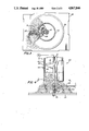
- FIG. 1 is a fragmentary, perspective view of a pre-treatment bin for wood chips and a wood chip feeder in accordance with the present invention.
- FIG. 2 is a view in cross section of the wood chip bin and feeder taken along the plane indicated by line 2--2 of FIG. 1.
- skirt 40 provides a seal between the mound of wood chips 9 and tube 12 so that the steam and/or other chemicals within the bin do not freely escape, and outside air does not freely enter into the bin. Gases cannot readily pass through the mound.
- skirt 40 has a circular cross section and a diameter slightly greaterthan that of tube 12 so that skirt 40 is longitudinally slidable along the exterior of the sidewall of tube 12 while providing a seal between its sidewall and that of tube 12.
- Tube 12 has a radial hole 42 in its sidewallto receive a bolt 44, and skirt 40 has a plurality of longitudinally spaced, radial holes 46 also to receive bolt 44 and thereby secure the skirt at a desired, adjustable height above plate 24.
- skirt 40 is secured at a height such that the lower end of the skirt engages the moundof wood chips 9 and thereby forms an effective seal or barrier between the remainder of the interior of bin 8 and the interior portion of tube 12 which is in communication with the external environment.
- skirt 40 atthis height prevents the steam and/or other gases within the bin from escaping and outside air from entering into the bin. Because the height ofskirt 40 is adjustable and the mound of wood chips is malleable, skirt 40 need not be manufactured or maintained at a precise length.
- FIGS. 4 and 5 illustrate another feeder generally designated 60 in accordance with another embodiment of the present invention.
- Feeder 60 is identical to feeder 10 except for the following.
- feeder 60 includes rotating plate 64 driven by drive shaft 18, and a stationary bar or plow 68 to knock the wood chips off the rotating plate.
- Drive shaft 18 is coupled to plate 64 by a key 65 protruding radially of the drive shaft and received in a slot 67 in plate 64.
- the lower end of drive shaft 18 is rotatably mounted in bearing 70 in the floor of bin 8.
- Stationary plow 68 may comprise a single, straight bar or a star-shaped assembly as illustrated to distribute the wood chips more evenly through the treatment bin 8.
- the feed screw 14 in both embodiments of the invention is optional and, if desired, may be omitted so that gravity alone forms wood chips 9 into the mound. In such case, motor 16 and drive shaft 18 are still provided to drive either plow 28 or plate 64. Moreover, if desired, tube 12 and the remainder of feeders 10 and 60 may be angled from the vertical. Therefore, the invention has been disclosed by way of illustration and not limitation, and reference should be made to the following claims to determine the scope of the invention.
Landscapes
- Paper (AREA)
Abstract
Description
Claims (4)
Priority Applications (1)
| Application Number | Priority Date | Filing Date | Title |
|---|---|---|---|
| US07/249,662 US4867846A (en) | 1988-09-27 | 1988-09-27 | Apparatus for feeding wood chips to a treatment bin |
Applications Claiming Priority (1)
| Application Number | Priority Date | Filing Date | Title |
|---|---|---|---|
| US07/249,662 US4867846A (en) | 1988-09-27 | 1988-09-27 | Apparatus for feeding wood chips to a treatment bin |
Publications (1)
| Publication Number | Publication Date |
|---|---|
| US4867846A true US4867846A (en) | 1989-09-19 |
Family
ID=22944457
Family Applications (1)
| Application Number | Title | Priority Date | Filing Date |
|---|---|---|---|
| US07/249,662 Expired - Lifetime US4867846A (en) | 1988-09-27 | 1988-09-27 | Apparatus for feeding wood chips to a treatment bin |
Country Status (1)
| Country | Link |
|---|---|
| US (1) | US4867846A (en) |
Cited By (18)
| Publication number | Priority date | Publication date | Assignee | Title |
|---|---|---|---|---|
| US20090020562A1 (en) * | 2004-11-03 | 2009-01-22 | Dario Rea | Device for feeding a product, in particular an infusion product, to a packaging machine |
| US20090098618A1 (en) * | 2007-10-10 | 2009-04-16 | Murray Burke | Treatment of lignocellulosic materials utilizing disc refining and enzymatic hydrolysis |
| US20090098617A1 (en) * | 2007-10-10 | 2009-04-16 | Murray Burke | Enzymatic treatment under vacuum of lignocellulosic materials |
| US20090098616A1 (en) * | 2007-10-09 | 2009-04-16 | Murray Burke | Enzymatic treatment of lignocellulosic materials |
| US20100024806A1 (en) * | 2008-07-24 | 2010-02-04 | Sunopta Bioprocess Inc. | Method and apparatus for conveying a cellulosic feedstock |
| US20100024807A1 (en) * | 2008-07-24 | 2010-02-04 | Sunopta Bioprocess Inc. | Method and apparatus for treating a cellulosic feedstock |
| US20100024809A1 (en) * | 2008-07-24 | 2010-02-04 | Sunopta Bioprocess Inc. | Method and apparatus for conveying a cellulosic feedstock |
| US20100028089A1 (en) * | 2008-07-24 | 2010-02-04 | Sunopta Bioprocess Inc. | Method and apparatus for conveying a cellulosic feedstock |
| US20100024808A1 (en) * | 2008-07-24 | 2010-02-04 | Sunopta Bioprocess Inc. | Method and apparatus for treating a cellulosic feedstock |
| US20100186735A1 (en) * | 2009-01-23 | 2010-07-29 | Sunopta Bioprocess Inc. | Method and apparatus for conveying a cellulosic feedstock |
| US20100186736A1 (en) * | 2009-01-23 | 2010-07-29 | Sunopta Bioprocess Inc. | Method and apparatus for conveying a cellulosic feedstock |
| US20100221090A1 (en) * | 2009-02-27 | 2010-09-02 | Laidig Systems, Inc. | Cutter dome for reclaim system |
| US20110011391A1 (en) * | 2009-07-17 | 2011-01-20 | Sunopta Bioprocess Inc. | Method and apparatus for the heat treatment of a cellulosic feedstock upstream of hydrolysis |
| US20110192866A1 (en) * | 2010-02-10 | 2011-08-11 | Bruce Shaw | Aggregate Material Feeder |
| DE102011102678A1 (en) * | 2011-05-28 | 2012-11-29 | Robert Bosch Gmbh | Dosing device for variable quantity metering of bulk material e.g. wood fuel pellet, has metering gap which is variable and/or movable using dosing unit, so that loose portions of bulk material retained or fall through by metering gap |
| US8545633B2 (en) | 2009-08-24 | 2013-10-01 | Abengoa Bioenergy New Technologies, Inc. | Method for producing ethanol and co-products from cellulosic biomass |
| US8915644B2 (en) | 2008-07-24 | 2014-12-23 | Abengoa Bioenergy New Technologies, Llc. | Method and apparatus for conveying a cellulosic feedstock |
| US9127325B2 (en) | 2008-07-24 | 2015-09-08 | Abengoa Bioenergy New Technologies, Llc. | Method and apparatus for treating a cellulosic feedstock |
Citations (10)
| Publication number | Priority date | Publication date | Assignee | Title |
|---|---|---|---|---|
| US895489A (en) * | 1907-03-18 | 1908-08-11 | Orville M Morse | Feed-regulator. |
| US1104288A (en) * | 1914-07-21 | Knut Jakob Beskow | Roasting-furnace. | |
| US2100315A (en) * | 1935-05-27 | 1937-11-30 | Elmer E Harper | Weighing feeder |
| US2329948A (en) * | 1941-05-01 | 1943-09-21 | American Ore Reclamation Compa | Feeder means |
| US2459180A (en) * | 1943-12-04 | 1949-01-18 | Kamyr Ab | Apparatus for charging fibrous material into a digester |
| US2468712A (en) * | 1944-12-21 | 1949-04-26 | Babcock & Wilcox Co | Heat exchanger |
| US3703435A (en) * | 1967-11-09 | 1972-11-21 | Sunds Ab | Method for finely disintegrating pulp,preferentially cellulose pulp,in connection with the bleaching thereof with gaseous bleaching agent |
| US4071399A (en) * | 1976-09-01 | 1978-01-31 | Kamyr, Inc. | Apparatus and method for the displacement impregnation of cellulosic chips material |
| US4120410A (en) * | 1976-09-13 | 1978-10-17 | Shell Internationale Research Maatschappij B.V. | Apparatus for the supply of fuel powder to a gas-pressurized vessel |
| US4653674A (en) * | 1980-06-09 | 1987-03-31 | Ohbayashi-Gumi, Ltd. | Device for dispensing goods through annular dispensing port |
-
1988
- 1988-09-27 US US07/249,662 patent/US4867846A/en not_active Expired - Lifetime
Patent Citations (10)
| Publication number | Priority date | Publication date | Assignee | Title |
|---|---|---|---|---|
| US1104288A (en) * | 1914-07-21 | Knut Jakob Beskow | Roasting-furnace. | |
| US895489A (en) * | 1907-03-18 | 1908-08-11 | Orville M Morse | Feed-regulator. |
| US2100315A (en) * | 1935-05-27 | 1937-11-30 | Elmer E Harper | Weighing feeder |
| US2329948A (en) * | 1941-05-01 | 1943-09-21 | American Ore Reclamation Compa | Feeder means |
| US2459180A (en) * | 1943-12-04 | 1949-01-18 | Kamyr Ab | Apparatus for charging fibrous material into a digester |
| US2468712A (en) * | 1944-12-21 | 1949-04-26 | Babcock & Wilcox Co | Heat exchanger |
| US3703435A (en) * | 1967-11-09 | 1972-11-21 | Sunds Ab | Method for finely disintegrating pulp,preferentially cellulose pulp,in connection with the bleaching thereof with gaseous bleaching agent |
| US4071399A (en) * | 1976-09-01 | 1978-01-31 | Kamyr, Inc. | Apparatus and method for the displacement impregnation of cellulosic chips material |
| US4120410A (en) * | 1976-09-13 | 1978-10-17 | Shell Internationale Research Maatschappij B.V. | Apparatus for the supply of fuel powder to a gas-pressurized vessel |
| US4653674A (en) * | 1980-06-09 | 1987-03-31 | Ohbayashi-Gumi, Ltd. | Device for dispensing goods through annular dispensing port |
Cited By (27)
| Publication number | Priority date | Publication date | Assignee | Title |
|---|---|---|---|---|
| US20090020562A1 (en) * | 2004-11-03 | 2009-01-22 | Dario Rea | Device for feeding a product, in particular an infusion product, to a packaging machine |
| US20090098616A1 (en) * | 2007-10-09 | 2009-04-16 | Murray Burke | Enzymatic treatment of lignocellulosic materials |
| US20090098618A1 (en) * | 2007-10-10 | 2009-04-16 | Murray Burke | Treatment of lignocellulosic materials utilizing disc refining and enzymatic hydrolysis |
| US20090098617A1 (en) * | 2007-10-10 | 2009-04-16 | Murray Burke | Enzymatic treatment under vacuum of lignocellulosic materials |
| US8778084B2 (en) | 2008-07-24 | 2014-07-15 | Abengoa Bioenergy New Technologies, Llc. | Method and apparatus for treating a cellulosic feedstock |
| US8449680B2 (en) | 2008-07-24 | 2013-05-28 | Mascoma Canada Inc. | Method and apparatus for treating a cellulosic feedstock |
| US20100024809A1 (en) * | 2008-07-24 | 2010-02-04 | Sunopta Bioprocess Inc. | Method and apparatus for conveying a cellulosic feedstock |
| US20100028089A1 (en) * | 2008-07-24 | 2010-02-04 | Sunopta Bioprocess Inc. | Method and apparatus for conveying a cellulosic feedstock |
| US20100024808A1 (en) * | 2008-07-24 | 2010-02-04 | Sunopta Bioprocess Inc. | Method and apparatus for treating a cellulosic feedstock |
| US9127325B2 (en) | 2008-07-24 | 2015-09-08 | Abengoa Bioenergy New Technologies, Llc. | Method and apparatus for treating a cellulosic feedstock |
| US20100024807A1 (en) * | 2008-07-24 | 2010-02-04 | Sunopta Bioprocess Inc. | Method and apparatus for treating a cellulosic feedstock |
| US9010522B2 (en) | 2008-07-24 | 2015-04-21 | Abengoa Bioenergy New Technologies, Llc | Method and apparatus for conveying a cellulosic feedstock |
| US8915644B2 (en) | 2008-07-24 | 2014-12-23 | Abengoa Bioenergy New Technologies, Llc. | Method and apparatus for conveying a cellulosic feedstock |
| US8911557B2 (en) | 2008-07-24 | 2014-12-16 | Abengoa Bioenergy New Technologies, Llc. | Method and apparatus for conveying a cellulosic feedstock |
| US8900370B2 (en) | 2008-07-24 | 2014-12-02 | Abengoa Bioenergy New Technologies, Llc. | Method and apparatus for conveying a cellulosic feedstock |
| US20100024806A1 (en) * | 2008-07-24 | 2010-02-04 | Sunopta Bioprocess Inc. | Method and apparatus for conveying a cellulosic feedstock |
| US20100186736A1 (en) * | 2009-01-23 | 2010-07-29 | Sunopta Bioprocess Inc. | Method and apparatus for conveying a cellulosic feedstock |
| US9004742B2 (en) | 2009-01-23 | 2015-04-14 | Abengoa Bioenergy New Technologies, Llc. | Method and apparatus for conveying a cellulosic feedstock |
| US9033133B2 (en) | 2009-01-23 | 2015-05-19 | Abengoa Bioenergy New Technologies, Llc. | Method and apparatus for conveying a cellulosic feedstock |
| US20100186735A1 (en) * | 2009-01-23 | 2010-07-29 | Sunopta Bioprocess Inc. | Method and apparatus for conveying a cellulosic feedstock |
| US8177470B2 (en) * | 2009-02-27 | 2012-05-15 | Laidig Systems, Inc. | Cutter dome for reclaim system |
| US20100221090A1 (en) * | 2009-02-27 | 2010-09-02 | Laidig Systems, Inc. | Cutter dome for reclaim system |
| US20110011391A1 (en) * | 2009-07-17 | 2011-01-20 | Sunopta Bioprocess Inc. | Method and apparatus for the heat treatment of a cellulosic feedstock upstream of hydrolysis |
| US8545633B2 (en) | 2009-08-24 | 2013-10-01 | Abengoa Bioenergy New Technologies, Inc. | Method for producing ethanol and co-products from cellulosic biomass |
| US9335043B2 (en) | 2009-08-24 | 2016-05-10 | Abengoa Bioenergy New Technologies, Inc. | Method for producing ethanol and co-products from cellulosic biomass |
| US20110192866A1 (en) * | 2010-02-10 | 2011-08-11 | Bruce Shaw | Aggregate Material Feeder |
| DE102011102678A1 (en) * | 2011-05-28 | 2012-11-29 | Robert Bosch Gmbh | Dosing device for variable quantity metering of bulk material e.g. wood fuel pellet, has metering gap which is variable and/or movable using dosing unit, so that loose portions of bulk material retained or fall through by metering gap |
Similar Documents
| Publication | Publication Date | Title |
|---|---|---|
| US4867846A (en) | Apparatus for feeding wood chips to a treatment bin | |
| EP2435187B1 (en) | Grinder | |
| US5500083A (en) | Method of feeding cellulosic material to a digester using a chip bin with one dimensional convergence and side relief | |
| US4077450A (en) | Rotary drum wastewood chipper | |
| US4121967A (en) | Screw conveyor in pulp-making equipment | |
| US1911718A (en) | Hatotkr mill fob | |
| US4544104A (en) | Wood chipper | |
| US4074803A (en) | Screw conveyor having stopper bar means | |
| US7121486B1 (en) | Crusher | |
| KR101812141B1 (en) | Sawdust crushing device for composting | |
| US4240589A (en) | Rotary bark screen | |
| CA2181892C (en) | Chip bin assembly including a hollow transition with one dimensional convergence and side relief | |
| US3117671A (en) | Live-bottom bin | |
| US2960161A (en) | Device for discharging materials from vessels | |
| US4642189A (en) | Rotary screen of the vertical pressure type having pulp stock feed at different axial positions on the screen | |
| US4520964A (en) | Waste comminuting apparatus | |
| US3027925A (en) | Rotary cutter having a vertically upward intake | |
| US2319192A (en) | Pulverizing mill | |
| US4832554A (en) | Apparatus for charging combustible materials | |
| CN208377949U (en) | A kind of belt feeder containing storehouse | |
| KR920003899A (en) | Gear processing chestnuts | |
| US114588A (en) | Improvement in flock-cutting machines | |
| RU2021891C1 (en) | Chopping machine | |
| JPS63249792A (en) | Method and apparatus for separating undigested substance | |
| CN218797432U (en) | Seed detection device |
Legal Events
| Date | Code | Title | Description |
|---|---|---|---|
| AS | Assignment |
Owner name: CHAMPION INTERNATIONAL CORPORATION, ONE CHAMPION P Free format text: ASSIGNMENT OF ASSIGNORS INTEREST.;ASSIGNOR:FLECK, JOHN A.;REEL/FRAME:004948/0472 Effective date: 19880920 Owner name: CHAMPION INTERNATIONAL CORPORATION, ONE CHAMPION P Free format text: ASSIGNMENT OF ASSIGNORS INTEREST;ASSIGNOR:FLECK, JOHN A.;REEL/FRAME:004948/0472 Effective date: 19880920 |
|
| STCF | Information on status: patent grant |
Free format text: PATENTED CASE |
|
| FEPP | Fee payment procedure |
Free format text: PAYOR NUMBER ASSIGNED (ORIGINAL EVENT CODE: ASPN); ENTITY STATUS OF PATENT OWNER: LARGE ENTITY |
|
| FPAY | Fee payment |
Year of fee payment: 4 |
|
| FPAY | Fee payment |
Year of fee payment: 8 |
|
| FEPP | Fee payment procedure |
Free format text: PAYOR NUMBER ASSIGNED (ORIGINAL EVENT CODE: ASPN); ENTITY STATUS OF PATENT OWNER: LARGE ENTITY |
|
| FEPP | Fee payment procedure |
Free format text: PAYER NUMBER DE-ASSIGNED (ORIGINAL EVENT CODE: RMPN); ENTITY STATUS OF PATENT OWNER: LARGE ENTITY |
|
| FPAY | Fee payment |
Year of fee payment: 12 |
|
| SULP | Surcharge for late payment |
Year of fee payment: 11 |
|
| AS | Assignment |
Owner name: INTERNATIONAL PAPER COMPANY, CONNECTICUT Free format text: MERGER;ASSIGNOR:CHAMPION INTERNATIONAL CORPORATION;REEL/FRAME:013774/0338 Effective date: 20001231 |