US4864221A - Filter, phase-measuring device and method for application of said filter - Google Patents
Filter, phase-measuring device and method for application of said filter Download PDFInfo
- Publication number
- US4864221A US4864221A US07/214,721 US21472188A US4864221A US 4864221 A US4864221 A US 4864221A US 21472188 A US21472188 A US 21472188A US 4864221 A US4864221 A US 4864221A
- Authority
- US
- United States
- Prior art keywords
- signal
- phase
- filter
- value
- measuring
- Prior art date
- Legal status (The legal status is an assumption and is not a legal conclusion. Google has not performed a legal analysis and makes no representation as to the accuracy of the status listed.)
- Expired - Fee Related
Links
- 238000000034 method Methods 0.000 title claims abstract description 6
- 238000005259 measurement Methods 0.000 claims abstract description 11
- 230000006870 function Effects 0.000 claims description 11
- 238000005070 sampling Methods 0.000 claims description 7
- 238000001914 filtration Methods 0.000 claims 5
- 238000001514 detection method Methods 0.000 abstract description 12
- 230000005540 biological transmission Effects 0.000 abstract description 3
- 239000000203 mixture Substances 0.000 abstract 1
- 238000010586 diagram Methods 0.000 description 10
- 239000010432 diamond Substances 0.000 description 4
- 238000010897 surface acoustic wave method Methods 0.000 description 3
- 230000001427 coherent effect Effects 0.000 description 2
- 229910003460 diamond Inorganic materials 0.000 description 2
- 238000000926 separation method Methods 0.000 description 2
- 101100521334 Mus musculus Prom1 gene Proteins 0.000 description 1
- 239000000969 carrier Substances 0.000 description 1
- 238000006243 chemical reaction Methods 0.000 description 1
- 230000001934 delay Effects 0.000 description 1
- 238000011031 large-scale manufacturing process Methods 0.000 description 1
- 238000004519 manufacturing process Methods 0.000 description 1
Images


Classifications
-
- G—PHYSICS
- G01—MEASURING; TESTING
- G01R—MEASURING ELECTRIC VARIABLES; MEASURING MAGNETIC VARIABLES
- G01R25/00—Arrangements for measuring phase angle between a voltage and a current or between voltages or currents
Definitions
- the present invention relates to a filter, a phase-measuring device and a method to apply the said filter.
- the device according to the present invention can be used, in particular, to make phase measurements of a continuous signal.
- the main object of the present invention is a signal-processing filter characterized in that it has an odd value transfer function, the transfer function of the said filter being symmetrical in amplitude and anti-symmetrical in phase, with respect to the center frequency of the said filter.
- Another object of the present invention is a method for measuring the phase of a signal comprising several samples, characterized in that the phase measuring and/or signal sampling instant is determined by detecting the passage through 0 of the signal that has crossed a filter, the transfer function of which is anti-symmetrical in phase and symmetrical in amplitude with respect to the center frequency of the said filter.
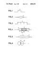
- FIG. 1 is a diagram showing the envelope of a signal
- FIG. 2 is a diagram illustrating the envelope of the signal of FIG. 1 after it has gone through an adapted filter
- FIG. 3 is a diagram illustrating the envelope of a signal
- FIG. 4 is a diagram illustrating the limits of variation of the signal of FIG. 3 after it has gone through the adapted filter
- FIG. 5 is an example of the envelope of the signal of FIG. 3 after it has gone through an adapted filter
- FIG. 6 is a diagram showing the phase of a signal after it has gone through an odd value filter
- FIG. 7 is a diagram of a first alternative embodiment of the device according to the invention.
- FIG. 8 is a diagram of a second alternative embodiment of the device according to the invention.
- FIG. 9 is a diagram of a third alternative embodiment of the device according to the invention.
- FIG. 10 is a diagram of a fourth alternative embodiment of the device according to the invention.
- FIG. 1 shows the envelope of a square signal 194.
- the signal 194 is a coherent signal with constant amplitude and phase.
- FIG. 2 shows the envelope 195 of the signal 194 of FIG. 1 after it has gone through an adapted filter.
- the phase of the signal at the output of the adapted filter is the same as that of the signal 194. Thus, if it is desired to measure this phase, the measurement can be done at any moment.
- the phase is measured when the amplitude of the signal at the output of the adapted filter is at its maximum.
- FIG. 3 shows a timing diagram comprising three successive signals 194.
- the signal is, for example, a coherent signal of constant amplitude.
- Each sample 194 of the signal has its own phase taking, for example, data transmissions in phase modulation.
- FIG. 4 shows the value that can be assumed by the value of the signal of FIG. 3 that has gone through a filter adapted to a sample 194 of the signal.
- the three diamonds 195 correspond to the signal that could be obtained by making each sample 194 of the signal go individually through the adapted filter.
- the total envelope of the signal begins with half of the first diamond 195, then includes a lined triangle 196, passes through the point 197, the value of which corresponds to that of the diamonds 195, another lined triangle 196 and ends with half of the last diamond 195. If the signal present at the output of the adapted filter is measured without taking any special precautions, there is the risk of measuring the value of the sum of the phase of two successive samples 195 of the signal.
- ⁇ 1 being the phase of the first sample 194 of the signal
- ⁇ 2 being the phase of the second sample 194 of the signal.
- FIG. 5 shows an example of an envelope of a signal that has crossed a filter adapted to the sample of the signal.
- a phase measurement made at the time corresponding to the point 197 can be used to measure the pure phase corresponding to a single sample of the signal 194.
- FIG. 6 shows the envelope of the signal 198 that has crossed an odd value filter. It can be seen that the signal is cancelled at the point 197.
- the present invention uses this phenomenon to determine the point 197 by which it is possible to measure the phase corresponding to a single sample 194 of the signal.
- the odd value filter is, for example, a surface acoustic wave (SAW) filter or a digital filter.
- An odd value or asymmetrical filter is a filter for which the transfer function is odd-numbered for the phase, with respect to the center frequency of the filter, and symmetrical for the amplitude, with respect to the center frequency of said filter.
- FIG. 7 shows a device 20 that enables the successive measurement of the phase of various signal samples.
- the device 20 comprises an adapted filter 140, a digital sampler 142 and a phase measuring device 192, connected in series.
- An odd value filter 141 is connected to the input of the adapted filter 140.
- the output of the odd value filter 141 is connected to the input of a phase detection device 191.
- the phase detection device 191 controls the sampling device 142.
- the detection device 191 is, for example, a Schmit trigger.
- the phase measuring device 192 is, for example, a phase comparator that compares the phase of the received signal with a reference phase received by a line 850.
- the adapted filters 140 and the odd value filters 141 are made, for example, in the form of a surface acoustic wave device.
- the adapted filters 140 and the odd value filters 141 are digital filters.
- the device according to the invention is connected to a device for the reception of phase modulated waves.
- the phase modulated waves transmit, for example, television broadcasts, radio broadcasts, control instructions or alphanumeric data.
- the receiving device has the following series-connected elements: a receiving antenna 4, a microwave amplifier 3, a frequency reduction device 82 and an intermediate frequency amplifier 3.
- the frequency reduction device 82 comprises, for example, a duplexer 80 connected. Firstly, to the microwave amplifier 3 and, secondly, to a local oscillator 81.
- the detection device 191 directly controls the phase measuring device 192.
- the detection device When the signal that has gone through the odd value filter 141 passes through 0, the detection device sends a control signal enabling the signal to be sampled.
- the passage of the signal through 0 corresponds to the point 197 of FIG. 6 and, hence, to the point 197 of FIGS. 4 and 5.
- FIG. 8 shows an example of an embodiment of the device according to the invention providing for the separation of the real and imaginary parts of the signal, namely the part in phase and the part in phase quadrature, and for the performance of separate processing operations on both parts of the signal until the phase is measured.
- phase of a signal may be deduced in a simple manner.
- the phase measuring device 192 is a permanent memory.
- the values I and Q of the signal are connected to the address bus 813 and the value of the phase is collected at the data bus 816.
- ROM read-only memory
- PROMs, EPROMs and EEPROMs will be used.
- RAMs random access memory
- FIG. 9 shows an alternative embodiment of a device of the invention comprising a phase locked loop (PLL).
- the phase locked device 143 is connected between the detection device 191 and the sampler 142.
- the phase locking device comprises, for example, the following elements connected in series: a phase comparator 144, a low-pass filter 145 and a voltage controlled oscillator 146.
- the output of the voltage controlled oscillator 146 is connected, firstly, to the sampling device 142 and, secondly, to a second input of the comparator 144.
- FIG. 10 shows an example of an embodiment of the device according to the invention associating the principle of separating the signal into real and imaginary parts and with the use of a phase-locked circuit 143.
- the device according to the invention comprises the following connected in series: a reception antenna 4, a microwave amplifier 3, a frequency reduction device 82, an intermediate frequency amplifier 3, a device 193 to separate the real and imaginary components of the signal, an adapted filter 140, a sampler 142, an address bus 813, a phase measuring device 192 and a data bus 816.
- the device 193 for separating the real and imaginary parts of the signal there are the following series-connected elements: an odd value filter 141, a detection device 191 and a phase-locked device 143.
- the phase-locked device 143 has, for example, a comparator 144 connected to a low-pass filter 145 and a voltage controlled oscillator 146.
- the adapted filter 140, the odd value filters 141, the sampler 142 and the detection device 191 simultaneously process the imaginary and real parts of the signal.
- the detection device 191 is connected to a first input of the comparator 144.
- the output of the voltage controlled oscillator 146 is connected, firstly, to the control device of the sampler 147 and, secondly, to a second input of the comparator 144.
- the present invention can be applied mainly to phase detection, demodulation and decoding.
- the present invention can be applied especially to the reception of television broadcasts, radio broadcasts or data transmission in phase modulation or in phase and amplitude modulation.
- the present invention can also be applied to radars.
Landscapes
- Physics & Mathematics (AREA)
- General Physics & Mathematics (AREA)
- Measuring Phase Differences (AREA)
- Stabilization Of Oscillater, Synchronisation, Frequency Synthesizers (AREA)
- Digital Transmission Methods That Use Modulated Carrier Waves (AREA)
- Radar Systems Or Details Thereof (AREA)
Abstract
Description
Claims (11)
Applications Claiming Priority (2)
| Application Number | Priority Date | Filing Date | Title |
|---|---|---|---|
| FR8613938A FR2604794B1 (en) | 1986-10-07 | 1986-10-07 | FILTER, PHASE MEASURING DEVICE AND METHOD USING THE SAME |
| FR8613938 | 1986-10-07 |
Publications (1)
| Publication Number | Publication Date |
|---|---|
| US4864221A true US4864221A (en) | 1989-09-05 |
Family
ID=9339609
Family Applications (1)
| Application Number | Title | Priority Date | Filing Date |
|---|---|---|---|
| US07/214,721 Expired - Fee Related US4864221A (en) | 1986-10-07 | 1987-10-06 | Filter, phase-measuring device and method for application of said filter |
Country Status (6)
| Country | Link |
|---|---|
| US (1) | US4864221A (en) |
| EP (1) | EP0286664B1 (en) |
| AU (1) | AU8039887A (en) |
| DE (1) | DE3786012T2 (en) |
| FR (1) | FR2604794B1 (en) |
| WO (1) | WO1988002867A1 (en) |
Cited By (3)
| Publication number | Priority date | Publication date | Assignee | Title |
|---|---|---|---|---|
| US6703980B2 (en) | 2000-07-28 | 2004-03-09 | Thales | Active dual-polarization microwave reflector, in particular for electronically scanning antenna |
| US6999535B1 (en) * | 2000-05-30 | 2006-02-14 | Nokia Mobile Phones Limited | Apparatus, and associated method, for recovering a desired component of a receive signal received at a radio device |
| US20090009296A1 (en) * | 2006-02-15 | 2009-01-08 | Sensomatic Electronics Corporation | Rf Switched Rfid Multiplexer |
Citations (2)
| Publication number | Priority date | Publication date | Assignee | Title |
|---|---|---|---|---|
| US4243935A (en) * | 1979-05-18 | 1981-01-06 | The United States Of America As Represented By The Secretary Of The Navy | Adaptive detector |
| EP0128804A1 (en) * | 1983-05-30 | 1984-12-19 | Mlr Electronique | Method of processing radio-electrical signals for radio navigation, and receiver for carrying out the method |
-
1986
- 1986-10-07 FR FR8613938A patent/FR2604794B1/en not_active Expired
-
1987
- 1987-10-06 DE DE87906674T patent/DE3786012T2/en not_active Expired - Fee Related
- 1987-10-06 WO PCT/FR1987/000383 patent/WO1988002867A1/en not_active Ceased
- 1987-10-06 EP EP87906674A patent/EP0286664B1/en not_active Expired - Lifetime
- 1987-10-06 US US07/214,721 patent/US4864221A/en not_active Expired - Fee Related
- 1987-10-06 AU AU80398/87A patent/AU8039887A/en not_active Abandoned
Patent Citations (3)
| Publication number | Priority date | Publication date | Assignee | Title |
|---|---|---|---|---|
| US4243935A (en) * | 1979-05-18 | 1981-01-06 | The United States Of America As Represented By The Secretary Of The Navy | Adaptive detector |
| EP0128804A1 (en) * | 1983-05-30 | 1984-12-19 | Mlr Electronique | Method of processing radio-electrical signals for radio navigation, and receiver for carrying out the method |
| US4695843A (en) * | 1983-05-30 | 1987-09-22 | Mlr Electronic | Method for processing radio signals for radionavigation and receiver for carrying out the said method |
Non-Patent Citations (4)
| Title |
|---|
| G. Uohlbacher et al.; "Bauelement e mit . . . ", Nachrichteu Elektronik, vol. 32, #6, Jun. 1978, pp. 181-187, see p. 186, para 4.1. |
| G. Uohlbacher et al.; Bauelement e mit . . . , Nachrichteu Elektronik, vol. 32, 6, Jun. 1978, pp. 181 187, see p. 186, para 4.1. * |
| List (2 pages) of U.S. Applications/Patents of Applicants (Applicants Attorney does not have copies in the file). * |
| List (2 pages) of U.S. Applications/Patents of Applicants--(Applicants Attorney does not have copies in the file). |
Cited By (4)
| Publication number | Priority date | Publication date | Assignee | Title |
|---|---|---|---|---|
| US6999535B1 (en) * | 2000-05-30 | 2006-02-14 | Nokia Mobile Phones Limited | Apparatus, and associated method, for recovering a desired component of a receive signal received at a radio device |
| US6703980B2 (en) | 2000-07-28 | 2004-03-09 | Thales | Active dual-polarization microwave reflector, in particular for electronically scanning antenna |
| US20090009296A1 (en) * | 2006-02-15 | 2009-01-08 | Sensomatic Electronics Corporation | Rf Switched Rfid Multiplexer |
| US8941471B2 (en) * | 2006-02-15 | 2015-01-27 | Tyco Fire & Security Gmbh | RF switched RFID multiplexer |
Also Published As
| Publication number | Publication date |
|---|---|
| FR2604794A1 (en) | 1988-04-08 |
| DE3786012T2 (en) | 1993-11-18 |
| FR2604794B1 (en) | 1988-12-02 |
| WO1988002867A1 (en) | 1988-04-21 |
| AU8039887A (en) | 1988-05-06 |
| EP0286664A1 (en) | 1988-10-19 |
| DE3786012D1 (en) | 1993-07-01 |
| EP0286664B1 (en) | 1993-05-26 |
Similar Documents
| Publication | Publication Date | Title |
|---|---|---|
| US4464770A (en) | Synchronous radio or television receiver with analog high frequency section followed by digital low frequency section | |
| US5159281A (en) | Digital demodulator using numerical processor to evaluate period measurements | |
| FI106748B (en) | Method and apparatus for measuring the phase accuracy and amplitude profile of a uniform phase modulated signal | |
| US4254503A (en) | Radio receiver for tone modulated signals | |
| US4800577A (en) | GPS receiver | |
| US5113189A (en) | Frequency translating coherent analog to digital conversion system for modulated signals | |
| CA2104658A1 (en) | Ils signal analysis device and method | |
| US4827515A (en) | Digital demodulator | |
| EP0792011B1 (en) | A digital phase detector | |
| US4321549A (en) | Switching quadrature detector | |
| US4965810A (en) | Digital differential phase-shift keyed decoder | |
| FI87960C (en) | FREKVENSSKILLNADSDETEKTOR (FDD) OCH EN BAERVAOGSMODULERAD MOTTAGARE INNEHAOLLANDE EN DYLIK FDD | |
| US5675498A (en) | Measuring amplitude of sparsely sampled sinusoidal signal | |
| US4864221A (en) | Filter, phase-measuring device and method for application of said filter | |
| JP2003060720A (en) | Jitter measurement device | |
| US5079513A (en) | Demodulator and radio receiver having such a demodulator | |
| US4706261A (en) | Differential phase modulation | |
| JPH04501489A (en) | Digital FM squelch detector | |
| EP0310960A3 (en) | Digital lock-in amplifier | |
| GB977474A (en) | Tone frequency control means for keyed filtered systems | |
| JP2504243B2 (en) | Demodulation method | |
| JP2659963B2 (en) | Receiver | |
| JP2743635B2 (en) | Signal receiver | |
| EP0614268B1 (en) | Method and apparatus for producing a difference signal between signal frequencies, and for detection of modulation | |
| JPS6444153A (en) | Demodulator |
Legal Events
| Date | Code | Title | Description |
|---|---|---|---|
| AS | Assignment |
Owner name: THOMSON-CSF, 173, BLVD., HAUSSMANN 75008 PARIS (FR Free format text: ASSIGNMENT OF ASSIGNORS INTEREST.;ASSIGNORS:FOUCHE, YVON;ELLEAUME, PHILIPPE;DRABOWITCH, SERGE;REEL/FRAME:004940/0920 Effective date: 19880524 Owner name: THOMSON-CSF,FRANCE Free format text: ASSIGNMENT OF ASSIGNORS INTEREST;ASSIGNORS:FOUCHE, YVON;ELLEAUME, PHILIPPE;DRABOWITCH, SERGE;REEL/FRAME:004940/0920 Effective date: 19880524 Owner name: THOMSON-CSF, FRANCE Free format text: ASSIGNMENT OF ASSIGNORS INTEREST;ASSIGNORS:FOUCHE, YVON;ELLEAUME, PHILIPPE;DRABOWITCH, SERGE;REEL/FRAME:004940/0920 Effective date: 19880524 |
|
| FEPP | Fee payment procedure |
Free format text: PAYOR NUMBER ASSIGNED (ORIGINAL EVENT CODE: ASPN); ENTITY STATUS OF PATENT OWNER: LARGE ENTITY |
|
| FPAY | Fee payment |
Year of fee payment: 4 |
|
| REMI | Maintenance fee reminder mailed | ||
| LAPS | Lapse for failure to pay maintenance fees | ||
| FP | Lapsed due to failure to pay maintenance fee |
Effective date: 19970910 |
|
| STCH | Information on status: patent discontinuation |
Free format text: PATENT EXPIRED DUE TO NONPAYMENT OF MAINTENANCE FEES UNDER 37 CFR 1.362 |