US4860593A - Ultrasonic device for measuring the rate of flow of fluid in a duct - Google Patents
Ultrasonic device for measuring the rate of flow of fluid in a duct Download PDFInfo
- Publication number
- US4860593A US4860593A US07/139,184 US13918487A US4860593A US 4860593 A US4860593 A US 4860593A US 13918487 A US13918487 A US 13918487A US 4860593 A US4860593 A US 4860593A
- Authority
- US
- United States
- Prior art keywords
- duct
- receivers
- signal
- fact
- fluid
- Prior art date
- Legal status (The legal status is an assumption and is not a legal conclusion. Google has not performed a legal analysis and makes no representation as to the accuracy of the status listed.)
- Expired - Fee Related
Links
Images

Classifications
-
- G—PHYSICS
- G01—MEASURING; TESTING
- G01F—MEASURING VOLUME, VOLUME FLOW, MASS FLOW OR LIQUID LEVEL; METERING BY VOLUME
- G01F1/00—Measuring the volume flow or mass flow of fluid or fluent solid material wherein the fluid passes through a meter in a continuous flow
- G01F1/76—Devices for measuring mass flow of a fluid or a fluent solid material
- G01F1/86—Indirect mass flowmeters, e.g. measuring volume flow and density, temperature or pressure
-
- G—PHYSICS
- G01—MEASURING; TESTING
- G01F—MEASURING VOLUME, VOLUME FLOW, MASS FLOW OR LIQUID LEVEL; METERING BY VOLUME
- G01F1/00—Measuring the volume flow or mass flow of fluid or fluent solid material wherein the fluid passes through a meter in a continuous flow
- G01F1/66—Measuring the volume flow or mass flow of fluid or fluent solid material wherein the fluid passes through a meter in a continuous flow by measuring frequency, phase shift or propagation time of electromagnetic or other waves, e.g. using ultrasonic flowmeters
- G01F1/662—Constructional details
-
- G—PHYSICS
- G01—MEASURING; TESTING
- G01F—MEASURING VOLUME, VOLUME FLOW, MASS FLOW OR LIQUID LEVEL; METERING BY VOLUME
- G01F1/00—Measuring the volume flow or mass flow of fluid or fluent solid material wherein the fluid passes through a meter in a continuous flow
- G01F1/66—Measuring the volume flow or mass flow of fluid or fluent solid material wherein the fluid passes through a meter in a continuous flow by measuring frequency, phase shift or propagation time of electromagnetic or other waves, e.g. using ultrasonic flowmeters
- G01F1/667—Arrangements of transducers for ultrasonic flowmeters; Circuits for operating ultrasonic flowmeters
Definitions
- the present invention relates to an ultrasonic device for measuring the rate of flow of fluid in a duct, particularly for measuring the mass flow rate of air passing along the inlet duct of a heat engine.
- ultrasonic measurement devices which are based on the principle of detecting the off-set in the phase difference presented by two ultrasonic frequency signals which are exchanged between respective electroacoustic transducers functioning alternately as transmitter element and receiver element and which are disposed in diametrically opposite positions in the duct itself.
- the circuit which drives the transducers and processes the signals supplied thereby is necessarily very complex and therefore as well as being relatively expensive can to some extent be subject to breakdowns.
- the object of the present invention is that of providing an ultrasonic device for measuring the rate of flow of fluid in a duct, particularly for the said application, which will be of very simple construction and therefore of low cost, and which will have a very reliable operation.
- an ultrasonic device for measuring the rate of flow of fluid in a duct, characterised by the fact that it comprises, disposed in opposite positions in the said duct:
- an ultrasonic signal transmitter and two signal receivers simultaneously and in which the signal paths between these receivers with the transmitter form respective predetermined angles of inclination with respect to the axis of the said duct; and including electronic means which receive the signals provided by the said receivers and produce therefrom a first signal dependent on the phase difference between the signals received by the said receivers, the said electronic means processing the said first signal together with a second received signal proportional to the pressure of the fluid in the said duct to provide an output signal indicative of the mass flow rate in the duct.
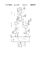
- FIG. 1 is a block schematic diagram of the device formed according to the principles of the present invention.
- FIG. 2 is a schematic sectional side view of a portion of a duct fitted with the electro-acoustic transducers of the device of the present invention
- FIG. 3 is a sectioned side view of an element which can be fitted in the device of the present invention.
- FIG. 4 is a perspective view of a different embodiment of a section of the duct with electro-acoustic transducers of the device of the present invention.
- this illustrates a longitudinal section of a portion 2 of the duct through which the fluid passes, for example air, the flow rate of which is to be measured;
- this portion 2 can be a portion of the air induction manifold for supply of an internal combustion engine, for example one provided with electronic fuel injection.
- each of the two receivers 4 and 4' is disposed in the direction of a straight line respectively 5 and 5' which starts from the centre of the transmitter 3 and forms a predetermined angle ⁇ and ⁇ - ⁇ with respect to the axis of the portion 2 of the duct.
- These two straight lines 5 and 5' further form a respective angle ⁇ with the perpendicular to the axis of the portion 2 of the duct, which originates from the transmitter 3, and represent the signal paths between the receivers and the transmitter.
- a wave guide 7 which serves to convey the ultrasonic signals which it receives from the transmitter 3 from an input mouth 8 along two internal channels 9 which are orientated along the directions of the straight lines 5 and 5' and which have respective output openings 10 and 10' in the duct section 2.
- Guide 7 thus directs the signals along the paths 5 and 5'.
- the transmitter 3 and the two receivers 4 and 4' are conveniently constituted by electro-acoustic transducers made with ceramic crystals which produce a voltage by the piezo-electric effect if stimulated by a variable pressure and vice versa.
- the transmitter 3 is supplied by an oscillator unit 12 which provides, for example, a square wave having a working frequency of several tens of KHz.
- the electric output signal from the receiver 4' arrives at the inverting amplifier and zero detector unit 14' which supplies an output signal when the input signal is substantially negative.
- the output signal of the unit 14' is therefore constituted by a rectangular wave with a duty cycle equal to about 0.5 so as to have a signal adapted for guiding a successive phase comparator unit 16.
- This output signal from the unit 14' is sent to a monostable multivibrator unit 15' which provides a short output pulse in substantial correspondence with the rising edge of the input wave.
- the output of the unit 15' is supplied to an input of the unit 16 to the other input of which is supplied the output of a similar chain constituted by units 14 and 15 similar to the units 14' and 15' described above.
- the inverting input of the unit 14 is in turn connected to the output of a phase shifter circuit 18 which receives the output signal from the receiver 4; this phase shifter circuit 18 serves to correct the different phase displacements between the signals from the receivers 4 and 4' which are due to the air path in the portion 2 of the duct and to the electric processing circuit, and is adjusted once and for all during calibration so as to give a nil phase shift between the signals from the receivers 4 and 4' when the air flow is nil.
- the phase comparator block 16 comprises a bistable multivibrator 16 of the SET - RESET type, formed with NOR logic gates so that the output signal, for example, goes to the high level when a signal arrives from the unit 15, and goes to the low level when a signal arrives from the unit 15'.
- the output of the bistable multivibrator is then supplied to a low pass filter 16" which forms an output signal 20 equal to the mid value of the input signals, and is in this way indicative of the degree of angular phase shift between the two signals provided by the receivers 4 and 4'.
- This signal 20 is then supplied to a unit 21 which receives another signal 22 from a pressure transducer 23 disposed in the portion 2 of the duct, and which operates in a manner which will be described hereinbelow to form an output signal 25 indicative of the rate of flow of fluid in the portion 2 of the duct.
- This signal 25 can therefore be utilised in a more convenient manner and can for example be provided to a central command and control unit 26 of an electronic injection system for an internal combustion engine.
- the ultrasonic waves which arrive from the transmitter 3 at the receiver 4' have a velocity C 2 which is given by the vector sum of the velocity of the sound c and the velocity u of the fluid in the portion 2 of the duct. Therefore, one has: ##EQU1## Now, considering the ultrasonic waves which propagate from the transmitter 3 towards the receiver 4, with an analogous treatment it results that:
- ⁇ c 2 has a value determined by the thermo dynamic state of the fluid.
- ⁇ c 2 ⁇ p
- p the pressure of the fluid
- ⁇ c p /c v
- the block 21 receives the signals 20 and 22 which represent, respectively, the values ⁇ and p, and also form the product with the value K 0 which is established on the basis of the parameters of the device and of the portion 2 of the duct so that the signal 25 which represents the value G of mass flow rate is produced directly.
- the portion of the duct, indicated 2' is of square cross section of side L and has within its interior, parallel to the axis of the portion 2' itself, two longitudinal partitions 30 of height L which are disposed facing one another and spaced on opposite sides of the central zone where the transmitter 3 and the two receivers 4 and 4' are disposed so as to define a space within which the ultrasonic waves which travel from the transmitter 3 to the receivers 4 and 4' are conveyed, in which the fluid certainly has a laminar flow.
- These two partitions 30 can conveniently be clad in sound absorbing material.
- the value of the constant K 0 for the multiplication block 21 is obviously varied.
Landscapes
- Physics & Mathematics (AREA)
- Fluid Mechanics (AREA)
- General Physics & Mathematics (AREA)
- Electromagnetism (AREA)
- Measuring Volume Flow (AREA)
Applications Claiming Priority (2)
| Application Number | Priority Date | Filing Date | Title |
|---|---|---|---|
| IT67982A/86 | 1986-12-30 | ||
| IT67982/86A IT1196886B (it) | 1986-12-30 | 1986-12-30 | Dispositivo ultrasonico di misurazione della portata di fluido in un condotto |
Publications (1)
| Publication Number | Publication Date |
|---|---|
| US4860593A true US4860593A (en) | 1989-08-29 |
Family
ID=11306927
Family Applications (1)
| Application Number | Title | Priority Date | Filing Date |
|---|---|---|---|
| US07/139,184 Expired - Fee Related US4860593A (en) | 1986-12-30 | 1987-12-29 | Ultrasonic device for measuring the rate of flow of fluid in a duct |
Country Status (6)
| Country | Link |
|---|---|
| US (1) | US4860593A (it) |
| EP (1) | EP0273385B1 (it) |
| BR (1) | BR8707160A (it) |
| DE (1) | DE3777985D1 (it) |
| ES (1) | ES2031115T3 (it) |
| IT (1) | IT1196886B (it) |
Cited By (16)
| Publication number | Priority date | Publication date | Assignee | Title |
|---|---|---|---|---|
| WO1995019559A2 (en) * | 1994-01-03 | 1995-07-20 | Panametrics, Inc. | Ultrasonic transducer system with temporal crosstalk isolation |
| WO1996006408A1 (en) * | 1994-08-24 | 1996-02-29 | Austin Curwood Hoggatt | Method and apparatus for measuring heat transfer in small diameter pipes using acoustic signals |
| US5918281A (en) * | 1996-05-28 | 1999-06-29 | Nabulsi; Haz | Personal speedometer |
| US6089104A (en) * | 1996-05-27 | 2000-07-18 | Chang; Hak Soo | Ultrasonic flow meter using transit time across tube chords for determining the flow rates |
| US6386047B2 (en) * | 1998-09-03 | 2002-05-14 | Chang Min Tech Co., Ltd. | Ultrasonic flow velocity measuring method using phase difference measurements |
| DE10062875A1 (de) * | 2000-12-16 | 2002-07-04 | Hydrometer Gmbh | Durchflussmesser |
| US20080066557A1 (en) * | 2006-09-20 | 2008-03-20 | Denso Corporation | Flowmeter element, mass flowmeter and mass flow measurement system |
| CN100455996C (zh) * | 2002-10-17 | 2009-01-28 | 恩德斯+豪斯流量技术股份有限公司 | 流量计 |
| US20100095782A1 (en) * | 2007-12-05 | 2010-04-22 | Ferencz Gyoergy | Method and apparatus for determining the flow parameters of a streaming medium |
| CN101441107B (zh) * | 2007-11-23 | 2010-07-21 | 上海工程技术大学 | 一种在超声波非接触物体振动测量中数据分析处理方法 |
| CN104405316A (zh) * | 2014-09-28 | 2015-03-11 | 济南大学 | 一种双压钻井液密度和质量流量的检测系统及检测方法 |
| US20170356773A1 (en) * | 2016-06-10 | 2017-12-14 | Virginia Polytechnic Institute And State University | System and method of non-intrusive anemometry |
| WO2018116071A1 (en) * | 2016-12-22 | 2018-06-28 | Fläkt Woods AB | Apparatus and method for measuring air flow |
| WO2018116070A1 (en) * | 2016-12-22 | 2018-06-28 | Fläkt Woods AB | Apparatus and method for measuring air flow |
| US20190376823A1 (en) * | 2016-06-27 | 2019-12-12 | Fläktgroup Sweden Ab | Apparatus and method for measuring air flow |
| US20220046856A1 (en) * | 2018-12-19 | 2022-02-17 | Agco International Gmbh | Grain cleaning system and method of controlling such |
Families Citing this family (10)
| Publication number | Priority date | Publication date | Assignee | Title |
|---|---|---|---|---|
| DE4118809C2 (de) * | 1991-06-07 | 1994-12-22 | Wagner Louise | Vorrichtung zur Messung kleiner Flüssigkeits- und Partikelströme |
| DE59205724D1 (de) * | 1991-06-07 | 1996-04-25 | Wagner Louise | Vorrichtung zur Messung kleiner Flüssigkeits- und Partikelströme |
| DK56593A (da) * | 1992-08-25 | 1994-02-26 | Kamstrup Metro As | Strømningsmåler |
| JP3175632B2 (ja) * | 1997-04-18 | 2001-06-11 | 松下電器産業株式会社 | シーンチェンジ検出方法およびシーンチェンジ検出装置 |
| FR2781047B1 (fr) * | 1998-07-10 | 2000-09-01 | Faure Herman | Debitmetre a ultrasons multicorde |
| CN101347752A (zh) * | 2008-07-28 | 2009-01-21 | 王洪福 | 搅拌剥皮机和搅拌着水机 |
| DE102008055031A1 (de) * | 2008-12-19 | 2010-09-09 | Endress + Hauser Flowtec Ag | Messsystem mit mindestens einem Ultraschallsender und mindestens zwei Ultraschallempfängern |
| JP5793644B2 (ja) * | 2010-11-11 | 2015-10-14 | パナソニックIpマネジメント株式会社 | 超音波式流量計測装置 |
| CN104197996B (zh) * | 2014-09-28 | 2016-08-24 | 中石化胜利石油工程有限公司钻井工艺研究院 | 一种串联式双压钻井液密度和质量流量检测系统 |
| GB201804449D0 (en) | 2018-03-20 | 2018-05-02 | Univ Warwick | Fluid flow speed method and apparatus |
Citations (7)
| Publication number | Priority date | Publication date | Assignee | Title |
|---|---|---|---|---|
| US2746291A (en) * | 1950-09-08 | 1956-05-22 | Robert C Swengel | Fluid velocity measuring system |
| US2826912A (en) * | 1948-12-27 | 1958-03-18 | Kritz Jack | Acoustic velocity measuring system |
| US3548653A (en) * | 1969-03-24 | 1970-12-22 | United Control Corp | Direction and velocity determining apparatus |
| US3555899A (en) * | 1966-11-01 | 1971-01-19 | Tokyo Keiki Seizosho Co Ltd | Ultrasonic flow quantity measuring system |
| US3727458A (en) * | 1969-12-12 | 1973-04-17 | British Coal Utilisation Res A | Measurement of rates of flow of gases |
| US4408589A (en) * | 1974-08-31 | 1983-10-11 | Robert Bosch Gmbh | Process and apparatus for operating an internal combustion engine |
| US4527432A (en) * | 1983-11-07 | 1985-07-09 | General Motors Corporation | Dual frequency acoustic fluid flow method and apparatus |
Family Cites Families (2)
| Publication number | Priority date | Publication date | Assignee | Title |
|---|---|---|---|---|
| DE3113522A1 (de) * | 1981-03-31 | 1982-11-04 | Siemens AG, 1000 Berlin und 8000 München | Waermemengen-messeinrichtung |
| US4527433A (en) * | 1983-10-25 | 1985-07-09 | General Motors Corporation | Method and apparatus for measuring fluid flow |
-
1986
- 1986-12-30 IT IT67982/86A patent/IT1196886B/it active
-
1987
- 1987-12-23 ES ES198787119121T patent/ES2031115T3/es not_active Expired - Lifetime
- 1987-12-23 DE DE8787119121T patent/DE3777985D1/de not_active Expired - Fee Related
- 1987-12-23 EP EP87119121A patent/EP0273385B1/en not_active Expired - Lifetime
- 1987-12-29 US US07/139,184 patent/US4860593A/en not_active Expired - Fee Related
- 1987-12-30 BR BR8707160A patent/BR8707160A/pt unknown
Patent Citations (7)
| Publication number | Priority date | Publication date | Assignee | Title |
|---|---|---|---|---|
| US2826912A (en) * | 1948-12-27 | 1958-03-18 | Kritz Jack | Acoustic velocity measuring system |
| US2746291A (en) * | 1950-09-08 | 1956-05-22 | Robert C Swengel | Fluid velocity measuring system |
| US3555899A (en) * | 1966-11-01 | 1971-01-19 | Tokyo Keiki Seizosho Co Ltd | Ultrasonic flow quantity measuring system |
| US3548653A (en) * | 1969-03-24 | 1970-12-22 | United Control Corp | Direction and velocity determining apparatus |
| US3727458A (en) * | 1969-12-12 | 1973-04-17 | British Coal Utilisation Res A | Measurement of rates of flow of gases |
| US4408589A (en) * | 1974-08-31 | 1983-10-11 | Robert Bosch Gmbh | Process and apparatus for operating an internal combustion engine |
| US4527432A (en) * | 1983-11-07 | 1985-07-09 | General Motors Corporation | Dual frequency acoustic fluid flow method and apparatus |
Cited By (26)
| Publication number | Priority date | Publication date | Assignee | Title |
|---|---|---|---|---|
| US5437194A (en) * | 1991-03-18 | 1995-08-01 | Panametrics, Inc. | Ultrasonic transducer system with temporal crosstalk isolation |
| WO1995019559A3 (en) * | 1994-01-03 | 1995-10-26 | Panametrics | Ultrasonic transducer system with temporal crosstalk isolation |
| WO1995019559A2 (en) * | 1994-01-03 | 1995-07-20 | Panametrics, Inc. | Ultrasonic transducer system with temporal crosstalk isolation |
| WO1996006408A1 (en) * | 1994-08-24 | 1996-02-29 | Austin Curwood Hoggatt | Method and apparatus for measuring heat transfer in small diameter pipes using acoustic signals |
| US6089104A (en) * | 1996-05-27 | 2000-07-18 | Chang; Hak Soo | Ultrasonic flow meter using transit time across tube chords for determining the flow rates |
| DE19722140C2 (de) * | 1996-05-27 | 2003-07-03 | Changmin Co | Ultraschall-Mehrkanal-Durchflußraten-Meßvorrichtung |
| US5918281A (en) * | 1996-05-28 | 1999-06-29 | Nabulsi; Haz | Personal speedometer |
| US6386047B2 (en) * | 1998-09-03 | 2002-05-14 | Chang Min Tech Co., Ltd. | Ultrasonic flow velocity measuring method using phase difference measurements |
| DE10062875A1 (de) * | 2000-12-16 | 2002-07-04 | Hydrometer Gmbh | Durchflussmesser |
| DE10062875B4 (de) * | 2000-12-16 | 2007-02-08 | Hydrometer Gmbh | Durchflussmesser |
| CN100455996C (zh) * | 2002-10-17 | 2009-01-28 | 恩德斯+豪斯流量技术股份有限公司 | 流量计 |
| US7549346B2 (en) | 2006-09-20 | 2009-06-23 | Denso Corporation | Flowmeter element, mass flowmeter and mass flow measurement system |
| US20080066557A1 (en) * | 2006-09-20 | 2008-03-20 | Denso Corporation | Flowmeter element, mass flowmeter and mass flow measurement system |
| DE102007042101B4 (de) * | 2006-09-20 | 2015-11-19 | Denso Corporation | Durchflussmesselement und Massendurchflussmesser |
| CN101441107B (zh) * | 2007-11-23 | 2010-07-21 | 上海工程技术大学 | 一种在超声波非接触物体振动测量中数据分析处理方法 |
| US10031011B2 (en) * | 2007-12-05 | 2018-07-24 | Uscom Limited | Ultrasonic flow meter including a single transmitting transducer and a pair of receiving transducers |
| US20100095782A1 (en) * | 2007-12-05 | 2010-04-22 | Ferencz Gyoergy | Method and apparatus for determining the flow parameters of a streaming medium |
| CN104405316A (zh) * | 2014-09-28 | 2015-03-11 | 济南大学 | 一种双压钻井液密度和质量流量的检测系统及检测方法 |
| CN104405316B (zh) * | 2014-09-28 | 2017-01-25 | 中石化胜利石油工程有限公司钻井工艺研究院 | 一种双压钻井液密度和质量流量的检测系统及检测方法 |
| US20170356773A1 (en) * | 2016-06-10 | 2017-12-14 | Virginia Polytechnic Institute And State University | System and method of non-intrusive anemometry |
| US10281307B2 (en) * | 2016-06-10 | 2019-05-07 | Virginia Tech Intellectual Properties, Inc. | System and method of non-intrusive anemometry |
| US20190376823A1 (en) * | 2016-06-27 | 2019-12-12 | Fläktgroup Sweden Ab | Apparatus and method for measuring air flow |
| US10816375B2 (en) * | 2016-06-27 | 2020-10-27 | Fläktgroup Sweden Ab | Apparatus and method for measuring air flow |
| WO2018116071A1 (en) * | 2016-12-22 | 2018-06-28 | Fläkt Woods AB | Apparatus and method for measuring air flow |
| WO2018116070A1 (en) * | 2016-12-22 | 2018-06-28 | Fläkt Woods AB | Apparatus and method for measuring air flow |
| US20220046856A1 (en) * | 2018-12-19 | 2022-02-17 | Agco International Gmbh | Grain cleaning system and method of controlling such |
Also Published As
| Publication number | Publication date |
|---|---|
| IT1196886B (it) | 1988-11-25 |
| EP0273385A3 (en) | 1989-08-30 |
| ES2031115T3 (es) | 1992-12-01 |
| IT8667982A0 (it) | 1986-12-30 |
| EP0273385B1 (en) | 1992-04-01 |
| BR8707160A (pt) | 1988-08-16 |
| DE3777985D1 (de) | 1992-05-07 |
| EP0273385A2 (en) | 1988-07-06 |
Similar Documents
| Publication | Publication Date | Title |
|---|---|---|
| US4860593A (en) | Ultrasonic device for measuring the rate of flow of fluid in a duct | |
| US4420983A (en) | Mass flow measurement device | |
| US4195517A (en) | Ultrasonic flowmeter | |
| US5796009A (en) | Method for measuring in a fluid with the aid of sing-around technique | |
| US4475406A (en) | Ultrasonic device for the measurement of the delivery of a fluid in a _conduit | |
| US4142414A (en) | Ultrasonic flow meter | |
| US4726235A (en) | Ultrasonic instrument to measure the gas velocity and/or the solids loading in a flowing gas stream | |
| US4011753A (en) | Method and device for measuring the flow velocity of media by means of ultrasound | |
| US4488428A (en) | Ultrasonic air flowmeter for motor vehicles | |
| US4240299A (en) | Method and apparatus for determining fluid density and mass flow | |
| US3473378A (en) | Ultrasonic flowmeter system | |
| US3623363A (en) | Ultrasonic flowmeter | |
| US4408589A (en) | Process and apparatus for operating an internal combustion engine | |
| USRE28686E (en) | Measurement of fluid flow rates | |
| US4583410A (en) | Timing circuit for acoustic flow meters | |
| US3204457A (en) | Ultrasonic flowmeter | |
| US2923155A (en) | Ultrasonic flowmeter | |
| SU838552A1 (ru) | Устройство дл определени концентрацииНЕРАСТВОРЕННОгО гАзА B жидКОСТи | |
| CN100356144C (zh) | 一种确定流动介质流速的方法和装置 | |
| JPS6261893B2 (it) | ||
| DE3271191D1 (en) | Measuring head for the determination of the amount of a flowing fluid | |
| EP0022828B1 (en) | A method of and apparatus for determining the mass flow rate of a fluid stream | |
| SU564601A1 (ru) | Ультразвуковой измеритель скорости потока среды | |
| EP3769049B1 (en) | Fluid flow speed method and apparatus | |
| SU1113735A1 (ru) | Устройство дл определени дефектов изделий по сигналам акустической эмиссии |
Legal Events
| Date | Code | Title | Description |
|---|---|---|---|
| AS | Assignment |
Owner name: WEBER S.R.L., 10125 TORINO (ITALY) CORSO MARCONI, Free format text: ASSIGNMENT OF ASSIGNORS INTEREST.;ASSIGNORS:CONCINI, ROBERTO DE;BRIGHI, MASSIMO;REEL/FRAME:004843/0518 Effective date: 19871204 Owner name: WEBER S.R.L.,ITALY Free format text: ASSIGNMENT OF ASSIGNORS INTEREST;ASSIGNORS:DE CONCINI, ROBERTO;BRIGHI, MASSIMO;REEL/FRAME:004843/0518 Effective date: 19871204 |
|
| REMI | Maintenance fee reminder mailed | ||
| LAPS | Lapse for failure to pay maintenance fees | ||
| FP | Lapsed due to failure to pay maintenance fee |
Effective date: 19930829 |
|
| STCH | Information on status: patent discontinuation |
Free format text: PATENT EXPIRED DUE TO NONPAYMENT OF MAINTENANCE FEES UNDER 37 CFR 1.362 |