US4860593A - Ultrasonic device for measuring the rate of flow of fluid in a duct - Google Patents

Ultrasonic device for measuring the rate of flow of fluid in a duct Download PDF

Info

Publication number
US4860593A
US4860593A US07/139,184 US13918487A US4860593A US 4860593 A US4860593 A US 4860593A US 13918487 A US13918487 A US 13918487A US 4860593 A US4860593 A US 4860593A
Authority
US
United States
Prior art keywords
duct
receivers
signal
fact
fluid
Prior art date
Legal status (The legal status is an assumption and is not a legal conclusion. Google has not performed a legal analysis and makes no representation as to the accuracy of the status listed.)
Expired - Fee Related
Application number
US07/139,184
Inventor
Roberto de Concini
Massimo Brighi
Current Assignee (The listed assignees may be inaccurate. Google has not performed a legal analysis and makes no representation or warranty as to the accuracy of the list.)
Weber SRL
Original Assignee
Weber SRL
Priority date (The priority date is an assumption and is not a legal conclusion. Google has not performed a legal analysis and makes no representation as to the accuracy of the date listed.)
Filing date
Publication date
Application filed by Weber SRL filed Critical Weber SRL
Assigned to WEBER S.R.L. reassignment WEBER S.R.L. ASSIGNMENT OF ASSIGNORS INTEREST. Assignors: BRIGHI, MASSIMO, DE CONCINI, ROBERTO
Application granted granted Critical
Publication of US4860593A publication Critical patent/US4860593A/en
Anticipated expiration legal-status Critical
Expired - Fee Related legal-status Critical Current

Links

Images

Classifications

    • GPHYSICS
    • G01MEASURING; TESTING
    • G01FMEASURING VOLUME, VOLUME FLOW, MASS FLOW OR LIQUID LEVEL; METERING BY VOLUME
    • G01F1/00Measuring the volume flow or mass flow of fluid or fluent solid material wherein the fluid passes through a meter in a continuous flow
    • G01F1/76Devices for measuring mass flow of a fluid or a fluent solid material
    • G01F1/86Indirect mass flowmeters, e.g. measuring volume flow and density, temperature or pressure
    • GPHYSICS
    • G01MEASURING; TESTING
    • G01FMEASURING VOLUME, VOLUME FLOW, MASS FLOW OR LIQUID LEVEL; METERING BY VOLUME
    • G01F1/00Measuring the volume flow or mass flow of fluid or fluent solid material wherein the fluid passes through a meter in a continuous flow
    • G01F1/66Measuring the volume flow or mass flow of fluid or fluent solid material wherein the fluid passes through a meter in a continuous flow by measuring frequency, phase shift or propagation time of electromagnetic or other waves, e.g. using ultrasonic flowmeters
    • G01F1/662Constructional details
    • GPHYSICS
    • G01MEASURING; TESTING
    • G01FMEASURING VOLUME, VOLUME FLOW, MASS FLOW OR LIQUID LEVEL; METERING BY VOLUME
    • G01F1/00Measuring the volume flow or mass flow of fluid or fluent solid material wherein the fluid passes through a meter in a continuous flow
    • G01F1/66Measuring the volume flow or mass flow of fluid or fluent solid material wherein the fluid passes through a meter in a continuous flow by measuring frequency, phase shift or propagation time of electromagnetic or other waves, e.g. using ultrasonic flowmeters
    • G01F1/667Arrangements of transducers for ultrasonic flowmeters; Circuits for operating ultrasonic flowmeters

Abstract

An ultrasonic device for measuring the rate of flow of fluid in a duct employs an ultrasonic signal transmitter and two ultrasonic signal receivers operating simultaneously, and the respective energy paths joining the receivers with the transmitter form predetermined angles of inclination with respect to the axis of the duct. Phase differences between the signals received by the receivers, and the pressure of the fluid in the duct, are used to form an output signal indicative of the mass flow rate of fluid in the duct.

Description

BACKGROUND OF THE INVENTION
The present invention relates to an ultrasonic device for measuring the rate of flow of fluid in a duct, particularly for measuring the mass flow rate of air passing along the inlet duct of a heat engine.
As is known, especially in the said application, and when the engine is fed by an electronic fuel injection system, it is particularly important to measure even very short term variations in the flow rate in a sufficiently precise and rapid manner for the purpose of correctly performing the various engine control strategies.
To overcome the disadvantages of slowness in response and of major breakdowns of moving parts, to which measurement devices of mechanical type are subject, ultrasonic measurement devices have been proposed, which are based on the principle of detecting the off-set in the phase difference presented by two ultrasonic frequency signals which are exchanged between respective electroacoustic transducers functioning alternately as transmitter element and receiver element and which are disposed in diametrically opposite positions in the duct itself. The circuit which drives the transducers and processes the signals supplied thereby is necessarily very complex and therefore as well as being relatively expensive can to some extent be subject to breakdowns.
SUMMARY OF THE INVENTION
The object of the present invention is that of providing an ultrasonic device for measuring the rate of flow of fluid in a duct, particularly for the said application, which will be of very simple construction and therefore of low cost, and which will have a very reliable operation.
According to the present invention there is provided an ultrasonic device for measuring the rate of flow of fluid in a duct, characterised by the fact that it comprises, disposed in opposite positions in the said duct:
an ultrasonic signal transmitter and two signal receivers simultaneously, and in which the signal paths between these receivers with the transmitter form respective predetermined angles of inclination with respect to the axis of the said duct; and including electronic means which receive the signals provided by the said receivers and produce therefrom a first signal dependent on the phase difference between the signals received by the said receivers, the said electronic means processing the said first signal together with a second received signal proportional to the pressure of the fluid in the said duct to provide an output signal indicative of the mass flow rate in the duct.
BRIEF DESCRIPTION OF THE DRAWINGS
For a better understanding of the present invention various embodiments thereof are now described purely by way of nonlimitative example with reference to the attached drawings, in which:
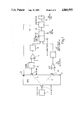
FIG. 1 is a block schematic diagram of the device formed according to the principles of the present invention;
FIG. 2 is a schematic sectional side view of a portion of a duct fitted with the electro-acoustic transducers of the device of the present invention;
FIG. 3 is a sectioned side view of an element which can be fitted in the device of the present invention; and
FIG. 4 is a perspective view of a different embodiment of a section of the duct with electro-acoustic transducers of the device of the present invention.
DETAILED DESCRIPTION OF THE INVENTION
With reference to FIG. 1, this illustrates a longitudinal section of a portion 2 of the duct through which the fluid passes, for example air, the flow rate of which is to be measured; this portion 2 can be a portion of the air induction manifold for supply of an internal combustion engine, for example one provided with electronic fuel injection.
On one side of the portion 2 of the duct, for example having a circular section of diameter d, as is better illustrated in FIG. 2, there is disposed an ultrasonic signal transmitter 3 and in a diametrically opposite region of this portion 2 there are disposed two ultrasonic signal receivers 4 and 4'. Each of the two receivers 4 and 4' is disposed in the direction of a straight line respectively 5 and 5' which starts from the centre of the transmitter 3 and forms a predetermined angle θ and π- θ with respect to the axis of the portion 2 of the duct. These two straight lines 5 and 5' further form a respective angle θ with the perpendicular to the axis of the portion 2 of the duct, which originates from the transmitter 3, and represent the signal paths between the receivers and the transmitter.
At the output of the transmitter 3, as is seen in FIG. 3, there can be fitted a wave guide 7 which serves to convey the ultrasonic signals which it receives from the transmitter 3 from an input mouth 8 along two internal channels 9 which are orientated along the directions of the straight lines 5 and 5' and which have respective output openings 10 and 10' in the duct section 2. Guide 7 thus directs the signals along the paths 5 and 5'.
The transmitter 3 and the two receivers 4 and 4' are conveniently constituted by electro-acoustic transducers made with ceramic crystals which produce a voltage by the piezo-electric effect if stimulated by a variable pressure and vice versa.
As is visible in FIG. 1, the transmitter 3 is supplied by an oscillator unit 12 which provides, for example, a square wave having a working frequency of several tens of KHz.
The electric output signal from the receiver 4' arrives at the inverting amplifier and zero detector unit 14' which supplies an output signal when the input signal is substantially negative. The output signal of the unit 14' is therefore constituted by a rectangular wave with a duty cycle equal to about 0.5 so as to have a signal adapted for guiding a successive phase comparator unit 16. This output signal from the unit 14' is sent to a monostable multivibrator unit 15' which provides a short output pulse in substantial correspondence with the rising edge of the input wave. The output of the unit 15' is supplied to an input of the unit 16 to the other input of which is supplied the output of a similar chain constituted by units 14 and 15 similar to the units 14' and 15' described above. The inverting input of the unit 14 is in turn connected to the output of a phase shifter circuit 18 which receives the output signal from the receiver 4; this phase shifter circuit 18 serves to correct the different phase displacements between the signals from the receivers 4 and 4' which are due to the air path in the portion 2 of the duct and to the electric processing circuit, and is adjusted once and for all during calibration so as to give a nil phase shift between the signals from the receivers 4 and 4' when the air flow is nil.
The phase comparator block 16 comprises a bistable multivibrator 16 of the SET - RESET type, formed with NOR logic gates so that the output signal, for example, goes to the high level when a signal arrives from the unit 15, and goes to the low level when a signal arrives from the unit 15'. The output of the bistable multivibrator is then supplied to a low pass filter 16" which forms an output signal 20 equal to the mid value of the input signals, and is in this way indicative of the degree of angular phase shift between the two signals provided by the receivers 4 and 4'.
This signal 20 is then supplied to a unit 21 which receives another signal 22 from a pressure transducer 23 disposed in the portion 2 of the duct, and which operates in a manner which will be described hereinbelow to form an output signal 25 indicative of the rate of flow of fluid in the portion 2 of the duct. This signal 25 can therefore be utilised in a more convenient manner and can for example be provided to a central command and control unit 26 of an electronic injection system for an internal combustion engine.
Before passing on to the description of the operation of the measuring device of the present invention there is here provided a brief theoretical treatment of the laws which correlate the difference between the phase of the ultrasonic waves received by the receivers 4 and 4' and the rate of flow of fluid in the portion 2 of the duct. Further, the generally well verified hypothesis is introduced that the velocity U of the fluid is constant in magnitude and direction in all the points at least of the laminer section along the axis of the portion 2 including the straight lines 5 and 5'.
With reference to FIG. 2, the ultrasonic waves which arrive from the transmitter 3 at the receiver 4' have a velocity C2 which is given by the vector sum of the velocity of the sound c and the velocity u of the fluid in the portion 2 of the duct. Therefore, one has: ##EQU1## Now, considering the ultrasonic waves which propagate from the transmitter 3 towards the receiver 4, with an analogous treatment it results that:
c.sub.1 =-u cosθ +c.sup.2 -u.sup.2 sin.sup.2 θ
If now we consider the phases φ1 and φ2 of the waves which propagate respectively from the transmitter 3 to the receiver 4 and from the transmitter 3 to the receiver 4'.
The phase φ of the wave which arrives at a receiver at any instant is equal to the phase φ0 at the transmitter plus 2π times the number of waves contained in the space between the source and the receiver. Therefore, if the distance between the transmitter 3 and the receiver 4 or 4' is written 1=d/cosα one can write: ##EQU2## from the relation λγ=c (where γ is the frequency of the ultrasonic wave) one has ##EQU3## The phase difference between the waves which arrive at the receivers 4 and 4' is: ##EQU4## By substituting the first indicated values for c1 and c2 one has: ##EQU5## Supposing it were possible to neglect u2 /c2 with respect to unity in that even at the maximum rate of flow of fluid envisaged, c would always be very much greater than u, then one could express the following linear relation between u and δφ. ##EQU6## The mass flow rate G is connected to the velocity of the fluid in the duct by means of the relation:
G=ρAu
where ρ is the density of the fluid and A is the cross section of the duct, and for FIG. 2, A=π/4 d2.
Proceeding to substitution, and bearing in mind the preceding linear relation, one has: ##EQU7## The product ρc2 has a value determined by the thermo dynamic state of the fluid. In particular, for a gas: ρc2 =γp, where p is the pressure of the fluid and γ=cp /cv, which latter is the ratio between the specific heats at constant volume and constant pressure, so that one has: ##EQU8## Therefore, with reference to FIG. 1, the block 21 receives the signals 20 and 22 which represent, respectively, the values δφ and p, and also form the product with the value K0 which is established on the basis of the parameters of the device and of the portion 2 of the duct so that the signal 25 which represents the value G of mass flow rate is produced directly.
In a variant embodiment illustrated in FIG. 4 the portion of the duct, indicated 2' is of square cross section of side L and has within its interior, parallel to the axis of the portion 2' itself, two longitudinal partitions 30 of height L which are disposed facing one another and spaced on opposite sides of the central zone where the transmitter 3 and the two receivers 4 and 4' are disposed so as to define a space within which the ultrasonic waves which travel from the transmitter 3 to the receivers 4 and 4' are conveyed, in which the fluid certainly has a laminar flow. These two partitions 30 can conveniently be clad in sound absorbing material. In the case of this duct 2' the value of the constant K0 for the multiplication block 21 is obviously varied.
The advantages obtained with the device of the present invention are evident from what has been described; in particular a particularly simple and efficient circuit configuration is obtained, which allows even very rapid variations in the mass flow rate of fluid to be detected with high precision of the order of several per cent.
Finally, it is clear that the embodiments of the present invention described and illustrated can have modifications and variations introduced thereto which do not depart from the inventive scope of the idea contained in it. For example, the form of the duct portion can be varied and the circuit configuration illustrated in FIG. 1 can be obtained differently, and the operation of the oscillator block 12 can be intermittent rather than continuous.

Claims (11)

I claim:
1. An ultrasonic device for measuring the rate of flow of fluid in a duct (2.2') characterized by the fact that it comprises, disposed in diametrically opposite positions in the said duct:
an ultrasonic signal transmitter (3) and respectively two ultrasonic signal receivers (4.4') operating simultaneously and in which the signal paths (5.5') extending respectively between the receivers (4.4') and the transmitter (3) form respective predetermined angles of inclination (θ, -θ) with respect to the axis of the said duct (2.2'); and including electronic means (15, 21) which receive signals provided by the said receivers (4,4'), and produce therefrom a first signal (20) dependent on the phase difference between the signals received by the said receivers (4, 4'), the said electronic means processing the said first signal (20) together with a second received signal (22) proportional to the pressure of the fluid in the said duct (2, 2') to provide an output signal (25) indicative of the mass flow rate of fluid in the duct (2, 2'), said duct including a pair of axially extending facing walls (30) disposed in the said duct (2') delimiting the section of the duct in which the said signal paths (5, 5') extending between the said receivers (4, 4') and the transmitter (3) are contained.
2. A device according to claim 1, characterized by the fact that it includes a wave guide unit (7) fitted to the said duct (2, 2') and operable to receive the said ultrasonic signals emitted by the said transmitter (3) and to convey them by means of internal channels (9) in the direction of the said signal paths (5, 5') towards the said receivers (4, 4').
3. A device according to claim 1, characterised by the fact that the said duct (2) has a circular cross section.
4. A device according to claim 1, characterized by the fact that the said duct (2') has rectangular cross section.
5. A device according to claim 1, characterised by the fact that the said electronic means include a phase comparator circuit (16) which receives electrical signals coming from the said two receivers (4, 4') and produces the said first signal (20).
6. A device according to claim 4, characterized by the fact that the said phase comparator circuit (16) includes a bistable multivibrator (16') followed by a low pass filter (16")
7. A device according to claim 5, characterized by the fact that the said electronic means includes respective circuit units (14, 14') which receive the electrical signals from the said two receivers (4, 4') and provide the said phase comparator circuit (16) with respective signals indicating whether or not a certain threshold value is exceeded.
8. A device according to claim 7, characterized by the fact that the said circuit units (14, 14') include zero flow detectors and are followed by respective monostable multivibrators (15, 15').
9. A device according to claim 5 characterised by the fact that it includes a phase shifting circuit (18) connected between one of the said two receivers (4, 4') and the said phase comparator circuit (16).
10. A device according to claim 1, characterised by the fact that the said duct (2, 2') is constituted by a portion of the air inlet duct of a heat engine.
11. An ultrasonic device for measuring the rate of flow of fluid in a duct (2, 2') characterized by the fact that it comprises, disposed in diametrically opposite positions in the said duct:
an ultrasonic signal transmitter (3) and respectively two ultrasonic signal receivers (4, 4") operating simultaneously and in which the signal paths (5, 5') extending respectively between the receivers (4, 4') and the transmitter (3) form respective predetermined angles of inclination (θ, -θ) with respect to the axis of the said duct (2, 2'); and including electronic means (15, 21) which receive signals provided by the said receivers (4, 4') and produce therefrom a first signal (20) dependent on the phase difference between the signals received by the said receivers (4, 4'), the said electronic means processing the said first signal (20) together with a second received signal (22) proportional to the pressure of the fluid in the said duct (2, 2') to provide an output signal (25) indicative of the mass flow rate of fluid in the duct (2, 2'), said electronic means including a phase comparator circuit (16) which receives electrical signals coming from the said two receivers (4, 4') and produces the said first signal (20), and a phase shifting circuit (18) connected between one of the said two receivers (4, 4') and the said phase comparator circuit (16).
US07/139,184 1986-12-30 1987-12-29 Ultrasonic device for measuring the rate of flow of fluid in a duct Expired - Fee Related US4860593A (en)

Applications Claiming Priority (2)

Application Number Priority Date Filing Date Title
IT67982/86A IT1196886B (en) 1986-12-30 1986-12-30 ULTRASONIC DEVICE FOR MEASURING THE FLOW RATE IN A DUCT
IT67982A/86 1986-12-30

Publications (1)

Publication Number Publication Date
US4860593A true US4860593A (en) 1989-08-29

Family

ID=11306927

Family Applications (1)

Application Number Title Priority Date Filing Date
US07/139,184 Expired - Fee Related US4860593A (en) 1986-12-30 1987-12-29 Ultrasonic device for measuring the rate of flow of fluid in a duct

Country Status (6)

Country Link
US (1) US4860593A (en)
EP (1) EP0273385B1 (en)
BR (1) BR8707160A (en)
DE (1) DE3777985D1 (en)
ES (1) ES2031115T3 (en)
IT (1) IT1196886B (en)

Cited By (16)

* Cited by examiner, † Cited by third party
Publication number Priority date Publication date Assignee Title
WO1995019559A2 (en) * 1994-01-03 1995-07-20 Panametrics, Inc. Ultrasonic transducer system with temporal crosstalk isolation
WO1996006408A1 (en) * 1994-08-24 1996-02-29 Austin Curwood Hoggatt Method and apparatus for measuring heat transfer in small diameter pipes using acoustic signals
US5918281A (en) * 1996-05-28 1999-06-29 Nabulsi; Haz Personal speedometer
US6089104A (en) * 1996-05-27 2000-07-18 Chang; Hak Soo Ultrasonic flow meter using transit time across tube chords for determining the flow rates
US6386047B2 (en) * 1998-09-03 2002-05-14 Chang Min Tech Co., Ltd. Ultrasonic flow velocity measuring method using phase difference measurements
DE10062875A1 (en) * 2000-12-16 2002-07-04 Hydrometer Gmbh Measurement of mass flow rate of liquids or gases using an ultrasonic transducer, with use of additional pressure gauges enabling determination of fluid density, temperature or viscosity
US20080066557A1 (en) * 2006-09-20 2008-03-20 Denso Corporation Flowmeter element, mass flowmeter and mass flow measurement system
CN100455996C (en) * 2002-10-17 2009-01-28 恩德斯+豪斯流量技术股份有限公司 Flowmeter
US20100095782A1 (en) * 2007-12-05 2010-04-22 Ferencz Gyoergy Method and apparatus for determining the flow parameters of a streaming medium
CN101441107B (en) * 2007-11-23 2010-07-21 上海工程技术大学 Data analysis processing method in ultrasonic wave non-contact object vibration measurement
CN104405316A (en) * 2014-09-28 2015-03-11 济南大学 System and method for detecting density and mass flow of dual-pressure drilling fluid
US20170356773A1 (en) * 2016-06-10 2017-12-14 Virginia Polytechnic Institute And State University System and method of non-intrusive anemometry
WO2018116071A1 (en) * 2016-12-22 2018-06-28 Fläkt Woods AB Apparatus and method for measuring air flow
WO2018116070A1 (en) * 2016-12-22 2018-06-28 Fläkt Woods AB Apparatus and method for measuring air flow
US20190376823A1 (en) * 2016-06-27 2019-12-12 Fläktgroup Sweden Ab Apparatus and method for measuring air flow
US20220046856A1 (en) * 2018-12-19 2022-02-17 Agco International Gmbh Grain cleaning system and method of controlling such

Families Citing this family (10)

* Cited by examiner, † Cited by third party
Publication number Priority date Publication date Assignee Title
DE59205724D1 (en) * 1991-06-07 1996-04-25 Wagner Louise Device for measuring small liquid and particle flows
DE4118809C2 (en) * 1991-06-07 1994-12-22 Wagner Louise Device for measuring small liquid and particle flows
DK56593A (en) * 1992-08-25 1994-02-26 Kamstrup Metro As flow meter
JP3175632B2 (en) * 1997-04-18 2001-06-11 松下電器産業株式会社 Scene change detection method and scene change detection device
FR2781047B1 (en) * 1998-07-10 2000-09-01 Faure Herman MULTI-CORD ULTRASONIC FLOW METER
CN101347752A (en) * 2008-07-28 2009-01-21 王洪福 Stirring-peeling machine and stirring dampener
DE102008055031A1 (en) * 2008-12-19 2010-09-09 Endress + Hauser Flowtec Ag Ultrasonic flow measuring system for determining and/or monitoring flow of measuring medium through measuring tube in e.g. process control engineering field, has projections formed symmetrically to intersection point of three planes
JP5793644B2 (en) * 2010-11-11 2015-10-14 パナソニックIpマネジメント株式会社 Ultrasonic flow meter
CN104197996B (en) * 2014-09-28 2016-08-24 中石化胜利石油工程有限公司钻井工艺研究院 A kind of tandem double pressure drilling fluid density and mass flow detecting system
GB201804449D0 (en) 2018-03-20 2018-05-02 Univ Warwick Fluid flow speed method and apparatus

Citations (7)

* Cited by examiner, † Cited by third party
Publication number Priority date Publication date Assignee Title
US2746291A (en) * 1950-09-08 1956-05-22 Robert C Swengel Fluid velocity measuring system
US2826912A (en) * 1948-12-27 1958-03-18 Kritz Jack Acoustic velocity measuring system
US3548653A (en) * 1969-03-24 1970-12-22 United Control Corp Direction and velocity determining apparatus
US3555899A (en) * 1966-11-01 1971-01-19 Tokyo Keiki Seizosho Co Ltd Ultrasonic flow quantity measuring system
US3727458A (en) * 1969-12-12 1973-04-17 British Coal Utilisation Res A Measurement of rates of flow of gases
US4408589A (en) * 1974-08-31 1983-10-11 Robert Bosch Gmbh Process and apparatus for operating an internal combustion engine
US4527432A (en) * 1983-11-07 1985-07-09 General Motors Corporation Dual frequency acoustic fluid flow method and apparatus

Family Cites Families (2)

* Cited by examiner, † Cited by third party
Publication number Priority date Publication date Assignee Title
DE3113522A1 (en) * 1981-03-31 1982-11-04 Siemens AG, 1000 Berlin und 8000 München HEAT AMOUNT MEASURING DEVICE
US4527433A (en) * 1983-10-25 1985-07-09 General Motors Corporation Method and apparatus for measuring fluid flow

Patent Citations (7)

* Cited by examiner, † Cited by third party
Publication number Priority date Publication date Assignee Title
US2826912A (en) * 1948-12-27 1958-03-18 Kritz Jack Acoustic velocity measuring system
US2746291A (en) * 1950-09-08 1956-05-22 Robert C Swengel Fluid velocity measuring system
US3555899A (en) * 1966-11-01 1971-01-19 Tokyo Keiki Seizosho Co Ltd Ultrasonic flow quantity measuring system
US3548653A (en) * 1969-03-24 1970-12-22 United Control Corp Direction and velocity determining apparatus
US3727458A (en) * 1969-12-12 1973-04-17 British Coal Utilisation Res A Measurement of rates of flow of gases
US4408589A (en) * 1974-08-31 1983-10-11 Robert Bosch Gmbh Process and apparatus for operating an internal combustion engine
US4527432A (en) * 1983-11-07 1985-07-09 General Motors Corporation Dual frequency acoustic fluid flow method and apparatus

Cited By (26)

* Cited by examiner, † Cited by third party
Publication number Priority date Publication date Assignee Title
US5437194A (en) * 1991-03-18 1995-08-01 Panametrics, Inc. Ultrasonic transducer system with temporal crosstalk isolation
WO1995019559A3 (en) * 1994-01-03 1995-10-26 Panametrics Ultrasonic transducer system with temporal crosstalk isolation
WO1995019559A2 (en) * 1994-01-03 1995-07-20 Panametrics, Inc. Ultrasonic transducer system with temporal crosstalk isolation
WO1996006408A1 (en) * 1994-08-24 1996-02-29 Austin Curwood Hoggatt Method and apparatus for measuring heat transfer in small diameter pipes using acoustic signals
US6089104A (en) * 1996-05-27 2000-07-18 Chang; Hak Soo Ultrasonic flow meter using transit time across tube chords for determining the flow rates
DE19722140C2 (en) * 1996-05-27 2003-07-03 Changmin Co Ultrasonic multi-channel flow rate measuring device
US5918281A (en) * 1996-05-28 1999-06-29 Nabulsi; Haz Personal speedometer
US6386047B2 (en) * 1998-09-03 2002-05-14 Chang Min Tech Co., Ltd. Ultrasonic flow velocity measuring method using phase difference measurements
DE10062875A1 (en) * 2000-12-16 2002-07-04 Hydrometer Gmbh Measurement of mass flow rate of liquids or gases using an ultrasonic transducer, with use of additional pressure gauges enabling determination of fluid density, temperature or viscosity
DE10062875B4 (en) * 2000-12-16 2007-02-08 Hydrometer Gmbh Flowmeter
CN100455996C (en) * 2002-10-17 2009-01-28 恩德斯+豪斯流量技术股份有限公司 Flowmeter
US7549346B2 (en) 2006-09-20 2009-06-23 Denso Corporation Flowmeter element, mass flowmeter and mass flow measurement system
US20080066557A1 (en) * 2006-09-20 2008-03-20 Denso Corporation Flowmeter element, mass flowmeter and mass flow measurement system
DE102007042101B4 (en) * 2006-09-20 2015-11-19 Denso Corporation Flow measuring element and mass flow meter
CN101441107B (en) * 2007-11-23 2010-07-21 上海工程技术大学 Data analysis processing method in ultrasonic wave non-contact object vibration measurement
US10031011B2 (en) * 2007-12-05 2018-07-24 Uscom Limited Ultrasonic flow meter including a single transmitting transducer and a pair of receiving transducers
US20100095782A1 (en) * 2007-12-05 2010-04-22 Ferencz Gyoergy Method and apparatus for determining the flow parameters of a streaming medium
CN104405316A (en) * 2014-09-28 2015-03-11 济南大学 System and method for detecting density and mass flow of dual-pressure drilling fluid
CN104405316B (en) * 2014-09-28 2017-01-25 中石化胜利石油工程有限公司钻井工艺研究院 System and method for detecting density and mass flow of dual-pressure drilling fluid
US20170356773A1 (en) * 2016-06-10 2017-12-14 Virginia Polytechnic Institute And State University System and method of non-intrusive anemometry
US10281307B2 (en) * 2016-06-10 2019-05-07 Virginia Tech Intellectual Properties, Inc. System and method of non-intrusive anemometry
US20190376823A1 (en) * 2016-06-27 2019-12-12 Fläktgroup Sweden Ab Apparatus and method for measuring air flow
US10816375B2 (en) * 2016-06-27 2020-10-27 Fläktgroup Sweden Ab Apparatus and method for measuring air flow
WO2018116071A1 (en) * 2016-12-22 2018-06-28 Fläkt Woods AB Apparatus and method for measuring air flow
WO2018116070A1 (en) * 2016-12-22 2018-06-28 Fläkt Woods AB Apparatus and method for measuring air flow
US20220046856A1 (en) * 2018-12-19 2022-02-17 Agco International Gmbh Grain cleaning system and method of controlling such

Also Published As

Publication number Publication date
EP0273385B1 (en) 1992-04-01
IT1196886B (en) 1988-11-25
EP0273385A2 (en) 1988-07-06
EP0273385A3 (en) 1989-08-30
BR8707160A (en) 1988-08-16
DE3777985D1 (en) 1992-05-07
ES2031115T3 (en) 1992-12-01
IT8667982A0 (en) 1986-12-30

Similar Documents

Publication Publication Date Title
US4860593A (en) Ultrasonic device for measuring the rate of flow of fluid in a duct
US4420983A (en) Mass flow measurement device
US4195517A (en) Ultrasonic flowmeter
US5796009A (en) Method for measuring in a fluid with the aid of sing-around technique
US4475406A (en) Ultrasonic device for the measurement of the delivery of a fluid in a _conduit
US4142414A (en) Ultrasonic flow meter
US4726235A (en) Ultrasonic instrument to measure the gas velocity and/or the solids loading in a flowing gas stream
US4011753A (en) Method and device for measuring the flow velocity of media by means of ultrasound
EP0631114A2 (en) Method and assembly for measuring mass flow or velocity flow of a fluid
US4488428A (en) Ultrasonic air flowmeter for motor vehicles
US3473378A (en) Ultrasonic flowmeter system
US3623363A (en) Ultrasonic flowmeter
US4408589A (en) Process and apparatus for operating an internal combustion engine
USRE28686E (en) Measurement of fluid flow rates
US4583410A (en) Timing circuit for acoustic flow meters
US3204457A (en) Ultrasonic flowmeter
US2923155A (en) Ultrasonic flowmeter
SU838552A1 (en) Device for measuring undissolved gas concentration in liquid
CN100356144C (en) Method and device for determining flow rate of a flowing medium
JPS6261893B2 (en)
DE3271191D1 (en) Measuring head for the determination of the amount of a flowing fluid
EP0022828B1 (en) A method of and apparatus for determining the mass flow rate of a fluid stream
SU564601A1 (en) Medium flow rate ultrasound meter
EP3769049B1 (en) Fluid flow speed method and apparatus
SU1113735A1 (en) Device for determination of articles flaws by acoustic emission signals

Legal Events

Date Code Title Description
AS Assignment

Owner name: WEBER S.R.L., 10125 TORINO (ITALY) CORSO MARCONI,

Free format text: ASSIGNMENT OF ASSIGNORS INTEREST.;ASSIGNORS:CONCINI, ROBERTO DE;BRIGHI, MASSIMO;REEL/FRAME:004843/0518

Effective date: 19871204

Owner name: WEBER S.R.L.,ITALY

Free format text: ASSIGNMENT OF ASSIGNORS INTEREST;ASSIGNORS:DE CONCINI, ROBERTO;BRIGHI, MASSIMO;REEL/FRAME:004843/0518

Effective date: 19871204

REMI Maintenance fee reminder mailed
LAPS Lapse for failure to pay maintenance fees
FP Lapsed due to failure to pay maintenance fee

Effective date: 19930829

STCH Information on status: patent discontinuation

Free format text: PATENT EXPIRED DUE TO NONPAYMENT OF MAINTENANCE FEES UNDER 37 CFR 1.362