US4850392A - Double poppet relief valve - Google Patents
Double poppet relief valve Download PDFInfo
- Publication number
- US4850392A US4850392A US07/193,859 US19385988A US4850392A US 4850392 A US4850392 A US 4850392A US 19385988 A US19385988 A US 19385988A US 4850392 A US4850392 A US 4850392A
- Authority
- US
- United States
- Prior art keywords
- poppet
- orificing
- sealing
- relief valve
- disposed
- Prior art date
- Legal status (The legal status is an assumption and is not a legal conclusion. Google has not performed a legal analysis and makes no representation as to the accuracy of the status listed.)
- Expired - Lifetime
Links
Images


Classifications
-
- F—MECHANICAL ENGINEERING; LIGHTING; HEATING; WEAPONS; BLASTING
- F16—ENGINEERING ELEMENTS AND UNITS; GENERAL MEASURES FOR PRODUCING AND MAINTAINING EFFECTIVE FUNCTIONING OF MACHINES OR INSTALLATIONS; THERMAL INSULATION IN GENERAL
- F16K—VALVES; TAPS; COCKS; ACTUATING-FLOATS; DEVICES FOR VENTING OR AERATING
- F16K47/00—Means in valves for absorbing fluid energy
- F16K47/04—Means in valves for absorbing fluid energy for decreasing pressure or noise level, the throttle being incorporated in the closure member
-
- E—FIXED CONSTRUCTIONS
- E21—EARTH DRILLING; MINING
- E21B—EARTH DRILLING, e.g. DEEP DRILLING; OBTAINING OIL, GAS, WATER, SOLUBLE OR MELTABLE MATERIALS OR A SLURRY OF MINERALS FROM WELLS
- E21B43/00—Methods or apparatus for obtaining oil, gas, water, soluble or meltable materials or a slurry of minerals from wells
- E21B43/25—Methods for stimulating production
- E21B43/26—Methods for stimulating production by forming crevices or fractures
- E21B43/267—Methods for stimulating production by forming crevices or fractures reinforcing fractures by propping
-
- F—MECHANICAL ENGINEERING; LIGHTING; HEATING; WEAPONS; BLASTING
- F16—ENGINEERING ELEMENTS AND UNITS; GENERAL MEASURES FOR PRODUCING AND MAINTAINING EFFECTIVE FUNCTIONING OF MACHINES OR INSTALLATIONS; THERMAL INSULATION IN GENERAL
- F16K—VALVES; TAPS; COCKS; ACTUATING-FLOATS; DEVICES FOR VENTING OR AERATING
- F16K1/00—Lift valves or globe valves, i.e. cut-off apparatus with closure members having at least a component of their opening and closing motion perpendicular to the closing faces
- F16K1/32—Details
- F16K1/34—Cutting-off parts, e.g. valve members, seats
- F16K1/44—Details of seats or valve members of double-seat valves
-
- F—MECHANICAL ENGINEERING; LIGHTING; HEATING; WEAPONS; BLASTING
- F16—ENGINEERING ELEMENTS AND UNITS; GENERAL MEASURES FOR PRODUCING AND MAINTAINING EFFECTIVE FUNCTIONING OF MACHINES OR INSTALLATIONS; THERMAL INSULATION IN GENERAL
- F16K—VALVES; TAPS; COCKS; ACTUATING-FLOATS; DEVICES FOR VENTING OR AERATING
- F16K15/00—Check valves
- F16K15/02—Check valves with guided rigid valve members
- F16K15/06—Check valves with guided rigid valve members with guided stems
-
- F—MECHANICAL ENGINEERING; LIGHTING; HEATING; WEAPONS; BLASTING
- F16—ENGINEERING ELEMENTS AND UNITS; GENERAL MEASURES FOR PRODUCING AND MAINTAINING EFFECTIVE FUNCTIONING OF MACHINES OR INSTALLATIONS; THERMAL INSULATION IN GENERAL
- F16K—VALVES; TAPS; COCKS; ACTUATING-FLOATS; DEVICES FOR VENTING OR AERATING
- F16K17/00—Safety valves; Equalising valves, e.g. pressure relief valves
- F16K17/02—Safety valves; Equalising valves, e.g. pressure relief valves opening on surplus pressure on one side; closing on insufficient pressure on one side
- F16K17/04—Safety valves; Equalising valves, e.g. pressure relief valves opening on surplus pressure on one side; closing on insufficient pressure on one side spring-loaded
-
- Y—GENERAL TAGGING OF NEW TECHNOLOGICAL DEVELOPMENTS; GENERAL TAGGING OF CROSS-SECTIONAL TECHNOLOGIES SPANNING OVER SEVERAL SECTIONS OF THE IPC; TECHNICAL SUBJECTS COVERED BY FORMER USPC CROSS-REFERENCE ART COLLECTIONS [XRACs] AND DIGESTS
- Y10—TECHNICAL SUBJECTS COVERED BY FORMER USPC
- Y10T—TECHNICAL SUBJECTS COVERED BY FORMER US CLASSIFICATION
- Y10T137/00—Fluid handling
- Y10T137/7722—Line condition change responsive valves
- Y10T137/7738—Pop valves
-
- Y—GENERAL TAGGING OF NEW TECHNOLOGICAL DEVELOPMENTS; GENERAL TAGGING OF CROSS-SECTIONAL TECHNOLOGIES SPANNING OVER SEVERAL SECTIONS OF THE IPC; TECHNICAL SUBJECTS COVERED BY FORMER USPC CROSS-REFERENCE ART COLLECTIONS [XRACs] AND DIGESTS
- Y10—TECHNICAL SUBJECTS COVERED BY FORMER USPC
- Y10T—TECHNICAL SUBJECTS COVERED BY FORMER US CLASSIFICATION
- Y10T137/00—Fluid handling
- Y10T137/7722—Line condition change responsive valves
- Y10T137/7837—Direct response valves [i.e., check valve type]
- Y10T137/7838—Plural
- Y10T137/7846—Mechanically interconnected
-
- Y—GENERAL TAGGING OF NEW TECHNOLOGICAL DEVELOPMENTS; GENERAL TAGGING OF CROSS-SECTIONAL TECHNOLOGIES SPANNING OVER SEVERAL SECTIONS OF THE IPC; TECHNICAL SUBJECTS COVERED BY FORMER USPC CROSS-REFERENCE ART COLLECTIONS [XRACs] AND DIGESTS
- Y10—TECHNICAL SUBJECTS COVERED BY FORMER USPC
- Y10T—TECHNICAL SUBJECTS COVERED BY FORMER US CLASSIFICATION
- Y10T137/00—Fluid handling
- Y10T137/7722—Line condition change responsive valves
- Y10T137/7837—Direct response valves [i.e., check valve type]
- Y10T137/7904—Reciprocating valves
Definitions
- This invention relates to relief valves for providing pressure relief in a pumping system during treatment of wells, and more particularly, to a relief valve having a double poppet, one poppet portion for orificing and another poppet portion for sealing.
- a screenout occurs when the fracture in the formation will physically not accept any more proppant. This results in a pressure rise measurable at the surface. This increase in pressure, or pressure "spike”, can occur over just a few seconds, and increases in the range of 600 to 4000 psi are not unusual. These pressure spikes occur too rapidly for operators to react. Therefore, a pressure relief device is required in the pumping system.
- Pressure relief valves have been used in such pumping systems for some time and are well known.
- the relief valve is connected to the discharge line of the pump, and the relief valve consists of a housing structure, a seat, a poppet and some means of applying force, such as pneumatic or hydraulic pressure source.
- the poppet generally performs two functions. The first is a sealing function, and the second is an orificing function.
- Such a previously known relief valve which is described in more detail herein, has a problem in that after opening, it will not reseal. This is due to the fact that when throttling the fluid during the orificing function of the valve, the proppants in the fluid, which are extremely abrasive, erode the sealing components.
- this erosion causes the valve to leak after only one operation. Such erosion can occur over a time span of just a few seconds. Obviously, if the valve will not reseal, it will leak, and this leakage is undesirable because it creates the potential for well flowback which can result in loss of fracturing fluid and is potentially hazardous.
- the relief valve of the present invention has a double poppet means with separate orificing and sealing poppet means.
- the orificing means When the valve is in the open position, the orificing means performs the throttling or orificing function where high fluid flow rates are present, and the sealing poppet means is kept in a zone of low pressure drop and low fluid velocity. While open, the orificing poppet means and the adjacent orificing surface sustain the erosion, and the sealing poppet means sustains relatively little wear.
- This concept used in conjunction with wear-resistant materials, provides extended life for the sealing components. The major advantage is that the valve may be operated several times without requiring repair.
- the double poppet relief valve of the present invention generally comprises housing means for connecting to a pumping system and double poppet means disposed in the housing means for resealing when in a closed position and for throttling fluid flow through the housing means when in an open position.
- the relief valve may further comprise piston means for providing a force on the double poppet means in response to a pressure from a pressure source. The force acts in a direction tending to close the double poppet means.
- the double poppet means preferably comprises sealing poppet means for sealingly engaging a poppet seat located within the housing means when in the closed position and orificing poppet means for throttling fluid flow adjacent an orificing surface located in the housing means when in the open position.
- the sealing poppet means is spaced from the poppet seat when in the open position such that wear on the sealing poppet means is minimized.
- the relief valve further comprises an inner surface located in the housing means such that an outer surface of the orificing poppet means passes this inner surface in close, spaced relationship thereto as the double poppet means is moved from the closed position to the open position. This insures that the double poppet means will be fully opened quickly, again minimizing wear on the sealing poppet means.
- the orificing surface and the inner surface are defined on an orificing wear insert disposed in the housing means.
- the relief valve comprises a push rod slidably disposed in the housing means.
- the sealing poppet means is characterized by a sealing poppet body attached to the push rod
- the orificing poppet means is characterized by an orificing poppet body attached to the push rod.
- the sealing poppet body and orificing poppet body are spaced from one another, and a poppet spacer may be disposed therebetween.
- a ring holder is attached to the push rod.
- the sealing poppet means is characterized by a sealing poppet ring disposed around the ring holder
- the orificing poppet means is characterized by an orificing poppet ring disposed around the ring holder.
- the sealing poppet ring and orificing poppet ring are preferably spaced from one another, and a ring spacer may be disposed around the ring holder and between the sealing and orifice poppet rings.
- the double poppet relief valve will open when the pressure acting on the inlet area exerts a force exceeding that of the pressure source acting on the piston means.
- orificing is carried out by the orificing poppet means with minimal wear on the sealing poppet means. Accordingly, when the valve is closed, the sealing poppet means will reseal on the poppet seat, thus allowing many operations.
- the orificing poppet means may have a larger cross-sectional area than the sealing poppet means so that the system pressure must decrease by a corresponding amount before the valve will reclose. Alternately, the sealing poppet means and orificing poppet means may be the same size so that the system pressure does not need to decrease before closing.
- An important object of the present invention is to provide a relief valve for a pumping system having a double poppet means for sealing when in a closed position and for throttling fluid flow when in an open position.
- An additional object of the invention is to provide a relief valve with separate sealing poppet means and orificing poppet means.
- Another object of the invention is to provide a relief valve for a well treatment pumping system which will reseal when closed after actuation.
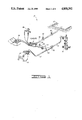
- FIG. 1 shows a typical pumping system for oil and well gas fracturing, utilizing the double poppet relief valve of the present invention.
- FIG. 2 shows a cross-sectional view of a prior art relief valve in both open and closed positions.
- FIG. 3 illustrates the double poppet relief valve of the present invention, shown in open and closed positions.
- FIG. 4 shows an alternate embodiment of the relief valve of the present invention in a closed position.
- FIG. 5 shows the alternate embodiment in an open position.
- Pumping system 12 also includes a pump 14 connected to a well head 16 by a pump discharge line 18.
- Relief valve 10 is connected to discharge line 18 by relief valve inlet line 20 by means of a tee 22.
- a manual shutoff valve 24 may be provided in relief valve inlet line 20 so that relief valve 10 may be isolated from discharge line 18 when necessary for repair or installation.
- a back check valve 26 may be placed in discharge line 18 downstream from tee 22 as desired.
- Relief valve 10 exhausts into relief valve discharge line 28 which flows the bypassed fluid from relief valve 10 into a pit 30.
- Stakes 32 of a kind known in the art may be used to hold relief valve inlet line 20 and relief valve discharge line 28 adjacent a ground surface as desired.
- a pressure source such as hydraulic or pneumatic power unit 34 is connected to relief valve 10.
- Other devices such as optional remote control unit 36 of a kind known in the art may also be connected to relief valve 10. The manner in which the hydraulic or pneumatic pressure is used in the operation of relief valve 10 will be discussed in further detail herein.
- FIG. 2 details of a prior art relief valve 40 are shown.
- the upper portion of FIG. 2 shows prior art relief valve 40 in an open position, and the lower portion of FIG. 2 shows the prior art relief valve in a closed position.
- Relief valve 40 is connected to pumping system 12 in the same manner as the present invention, as indicated in FIG. 1.
- Prior art relief valve 40 has an outer housing means 42 generally including a body 44, a cylinder 46 and a cylinder cover 48.
- Cylinder cover 48 is connected to cylinder 46 at threaded connection 50, and sealing means, such as 0-ring 52, provide sealing engagement between cylinder 46 and cylinder cover 48.
- Cylinder 46 is connected to body 44 at threaded connection 54.
- Cylinder 46 defines a bore 56 therein in which is slidably disposed a piston 58.
- a piston ring 60 provides sliding, sealing engagement between piston 58 and bore 56 of cylinder 46.
- bearing guide assembly 62 includes a bearing guide 64 with a cylindrical bearing 66 disposed along a central axis thereof. It will be seen that bearing guide assembly 62 is disposed adjacent body 44, and sealing means, such as 0-ring 68, provide sealing engagement therebetween.
- a push rod 70 is slidably disposed through bearing 66 and is attached to piston 58 by fastener means, such as bolt 72. Sealing means, such as seal ring 74, provide sealing engagement between push rod 70 and bearing 66.
- Push rod 70 is substantially coaxial with body 44 and extends away from bearing guide assembly 62 into body 44 in a direction opposite piston 58.
- a poppet assembly 76 is attached to an opposite end of push rod 70 from piston 58 by fastener means, such as bolt 78.
- Poppet assembly 76 includes a poppet 80 and a washer 82. Sealing means, such as 0-ring 84, provides sealing engagement between poppet assembly 76 and push rod 70.
- Body 44 has an end 86 opposite end 63 thereof and coaxial therewith. Adjacent end 86 is a transverse shoulder 88. A seat retainer 90 and a backup ring 92 are disposed in end 86 of body 44 such that backup ring 92 bears against shoulder 88. It will be seen that seat retainer 90 and backup ring 92 define a substantially annular seal groove 94. Disposed in seal groove 94 are an outer seat adapter 96, an inner seat adapter 98 and a poppet seat 100 disposed between the seat adapters. Poppet seat 100 is designed for sealing engagement with an outer circumferential surface 102 on poppet 80.
- seat retainer 90 forms an inlet 104 into body 44 of housing means 42.
- An outlet 106 formed in body 44 provides an outlet means for housing means 42.
- Attached to an outer side of cylinder cover 48 is a pressure manifold assembly 108. Sealing means such as O-ring 110 provides sealing engagement between manifold assembly 108 and cylinder cover 48. Cylinder cover 48 defines a bore 112 therethrough which is in fluid communication with manifold assembly 108.
- Manifold assembly 108 is connected to hydraulic or pneumatic power unit 34 such that a pressure source is provided to an outer chamber portion 114 in cylinder 46. It will be seen that piston ring 60 sealingly separates outer chamber portion 114 from an inner chamber portion 116 on the opposite side of piston 58.
- piston 58 When in the closed position, as indicated by the lower half of FIG. 2, piston 58 is adjacent bearing guide assembly 62, and poppet assembly 76 is positioned in inlet opening 104 such that outer surface 102 of poppet 80 is in sealing engagement with poppet seat 100.
- the pressure supplied to outer chamber portion 114 from power unit 34 is set at a predetermined level such that the pump pressure acting on poppet assembly 76 will open relief valve 40 at a preselected pump discharge or system pressure.
- poppet assembly 76, push rod 70 and piston 58 will move to the left, as viewed in FIG. 2, just enough to allow fluid pressure in inlet opening 104 to be relieved.
- an annular orificing or throttling flow passage is formed between poppet 80 and chamfered surface 120 of backup ring 92.
- Relief valve 40 works fairly well on clean fluids, but erosion of poppet 80 occurs on dirty fluids, and particularly proppant-laden slurries. The result is that the valve will not reseal after relieving on such fluids, and the system must then be operated with a leaking relief valve, or the relief valve must be disassembled and repaired. Either of these is an undesirable result.
- Relief valve 10 is shown in a closed position in the lower half of FIG. 3 and an open position in the upper half of FIG. 3.
- relief valve 10 includes a housing means 122 comprising a body 124 and cylinder 125 similar to body 44 and cylinder 46 in the prior art valve, and cylinder cover 48 which is substantially identical to the corresponding component in prior art valve 40.
- Cylinder 125 preferably has a longer stoke than cylinder 46.
- FIG. 3 the same reference numerals have been used when the components of relief valve 10 are essentially identical to those of prior art relief valve 40.
- Body 124 has an outlet 127 which is the same as outlet 106 on body 44 of prior art relief valve 40. Essentially, all of the components to the left of outlet 127, as shown in FIG. 3, are identical to that of prior art valve 40, except is shorter than push rod 70 in the prior art valve.
- Push rod 126 is slidably disposed through bearing 66 in bearing guide assembly 62 with sealing provided by a sealing means, such as 0-ring 74, and piston 58 is slidably disposed in cylinder 125 with sealing engagement provided by piston ring 60.
- Piston 58 is attached to push rod 126 in the same manner as in prior art relief valve 40.
- Outer chamber portion 114 is again provided with pressure from power unit 34 through manifold assembly 108.
- Body 124 defines a first bore 128 and a second bore 130 in the end thereof opposite piston 58.
- a small annular shoulder 132 extends between first bore 128 and second bore 130.
- a poppet sleeve 134 is disposed in body 124.
- Poppet sleeve 134 has a first outside diameter 136 which is adjacent first bore 128 in body 124 and a second outside diameter 138 which is adjacent second bore 130 in the body.
- Poppet sleeve 134 also has an annular shoulder 140, extending between first and second bores 136 and 138, which engages shoulder 132 in body 124.
- annular backup ring 142 At the outer end of poppet sleeve 134 is an annular backup ring 142 which is connected to the poppet sleeve at threaded connection 144.
- Poppet sleeve 134 is held in place in body 124 by a seat retainer 146.
- Seat retainer 146 extends into first bore 128 of body 124, and it will be seen that seat retainer 146 and backup ring 142 form a seat groove in which are positioned outer seat adapter 148, inner seat adapter 150 and poppet seat 152.
- new reference numerals have been used for the seat retainer, outer seat adapter, inner seat adapter and poppet seat in relief valve 10, it should be understood that these components could be essentially identical to those in prior art relief valve 40.
- poppet sleeve 134 At the inner end of poppet sleeve 134 is a tapered inner surface 154 against which is positioned an orificing wear insert 156. Wear insert 156 is held in place by means such as retainer ring 158. Sealing means, such as 0-ring 160, provide sealing engagement between wear insert 156 and tapered surface 154 of poppet sleeve 134.
- Double poppet means 164 generally comprises a sealing poppet assembly 166, an orificing poppet assembly 168, and a poppet spacer 170.
- Poppet spacer 170 has a first diameter 172, an enlarged second diameter 174 and a third diameter 176.
- Sealing poppet assembly 166 fits on first diameter 172 of poppet spacer 170 with sealing engagement provided therebetween by sealing means, such as 0-ring 178.
- orificing poppet assembly 168 fits on third diameter 176 of poppet spacer 170 with sealing engagement provided therebetween by sealing means, such as 0-ring 180.
- Sealing poppet assembly 166 comprises a sealing poppet body 182, a sealing poppet ring 184, a poppet cover 186 and sealing means, such as 0-ring 188, to provide sealing engagement between sealing poppet body 182 and sealing poppet ring 184.
- orificing poppet assembly 168 comprises an orificing poppet body 190, an orificing poppet ring 192, a poppet cover 194 and sealing means, such as 0-ring 196, for providing sealing engagement between orificing poppet body 190 and orificing poppet ring 192.
- orificing poppet assembly 168 may be larger than sealing poppet assembly 166 to give relief valve 10 a corresponding blow-down.
- Blow-down is the reduction in dynamic or flowing pressure below the relief pressure which is required before the valve will reclose.
- orificing poppet assembly 168 has a cross-sectional area approximately ten percent greater than that of sealing poppet assembly 166, the pressure must decrease by approximately ten percent below the relief pressure before the valve will start to close. This blow-down feature will prevent the valve from closing while pump 14 is still pumping at the relief pressure.
- sealing poppet assembly 166 and orificing poppet assembly 168 may be identical if desired so that there is no blow-down feature.
- Double poppet means 164 is connected to end 162 of push rod 126 by bolt 198 and washer 200.
- Bolt 198 extends through poppet spacer 170 and is threadingly engaged with push rod 126.
- Sealing means such as 0-ring 202, provide sealing engagment between end 162 of push rod 126 and orificing poppet assembly 168.
- Seat retainer 146 defines an inlet 204 into body 124, and as already mentioned, body 124 has an outlet 127. Inlet 204 and outlet 127 are connected to pumping system 12 in the manner already described for prior art relief valve 40.
- annular flow passage 212 is defined between sealing poppet assembly 166 and chamfered inner surface 214 of backup ring 142.
- cylinder 125 has a longer stroke than that in prior art relief valve 40. This longer stroke allows sealing poppet assembly 166 to be moved an adequate distance from backup ring 142.
- the cross-sectional area of passage 212 is significantly greater than the cross-sectional area of orificing passage 208. That is, the fluid velocity through passage 212 is much lower than the fluid velocity through orificing passage 208. The result is that wear on sealing poppet assembly 166 is significantly reduced compared to the prior art because the fluid flow velocity thereacross is so much less. Because of this, when relief valve 10 is reclosed, poppet ring 184 of sealing poppet assembly 166 will reseal against poppet seat 152.
- relief valve 10 may be used several times before it is necessary to repair it. This is a significant improvement over prior art relief valve 40 which generally must be repaired after one use. Not only is the cost of repair of relief valve 10 reduced, the fact that it reseals provides a better pumping system because the resealing feature provides that there is no leakage after cycling of the valve.
- FIG. 4 an alternate embodiment of the present invention is shown in a closed position, and generally designated by the numeral 220.
- Alternate embodiment relief valve 220 is shown in an open position in FIG. 5.
- Relief valve 220 is installed in pumping system 12 in the same manner as first embodiment relief valve 10, as indicated in FIG. 1.
- Alternate embodiment relief valve 220 includes a housing means 122 comprising a body 124 with an outlet 127 thereon. The components not shown in FIG. 4 are the same as in first embodiment relief valve 10.
- an alternate poppet sleeve 222 is disclosed in body 124.
- Poppet sleeve 222 has a first diameter 224 disposed adjacent first bore 128 in body 124 and a second diameter 226 disposed adjacent second bore 130 in body 124.
- a shoulder 228 between diameters 224 and 226 on poppet sleeve 222 bears against shoulder 132 in body 124.
- Poppet sleeve 222 defines a first bore 230, a second bore 232 and an inwardly directed shoulder 234 at the inner end of second bore 232.
- a seat retainer 236 holds poppet sleeve 222 in place.
- Seat retainer 236 has a diameter 238 adjacent first bore 128 in body 124.
- Sealing means such as 0-ring 240, may be provided between seat retainer 236 and body 124. Such sealing means could also be used in first embodiment relief valve 10.
- Seat retainer 236 also defines a bore 242 therein, substantially aligned with first bore 230 in poppet sleeve 222, with an inwardly directed shoulder 244 on the outer end of bore 242.
- Second wear insert 254 may also be referred to as an orificing wear insert 254.
- Double poppet means 260 comprises a ring holder 262 which fits over end 258 of push rod 256, a sealing poppet ring 263, a ring spacer 264 and an orificing poppet ring 265 which bears against an outwardly directed shoulder 266 on ring holder 262. Also included in double poppet means 260 is a ring retainer or poppet cover 268 which engages the outermost end of sealing poppet ring 263.
- Double poppet means 260 is attached to end 258 of push rod 256 by fastener means such as bolt 270 and washer 272.
- Sealing means such as 0-ring 274 provide sealing engagement between ring holder 262 and sealing poppet ring 263.
- sealing means, such as 0-ring 276, provide sealing engagement between ring holder 262 and end 258 of push rod 256.
- seat retainer 236 provides an inlet 278 into body 124. As long as the force exerted by the pressure in outer chamber portion 114 acting on piston 58 exceeds the force exerted by the pressure in inlet 278 acting on the area of the inlet, alternate relief valve 220 will remain closed, as with the other relief valves discussed herein.
- double poppet means 260 will move to the left as viewed in FIG. 4 in a manner similar to double poppet means 166 in first embodiment relief valve 10.
- double poppet means 260 opens, orificing poppet ring 265 moves adjacent and in close relationship to annular inside surface 280 of second wear insert 254.
- the fluid pressure then quickly forces double poppet means 260 further to the left, as best seen in FIG. 5, such that an annular orificing passage 282 is formed between orificing poppet ring 265 and chamfered inner orificing surface 284 of second wear insert 254.
- sealing poppet ring 263 is moved away from first wear insert 250 such that an annular flow passage 286 is defined between sealing poppet ring 263 and chamfered surface 288 of first wear insert 250.
- passage 286 has a substantially larger area than orificing passage 282, such that the fluid flow velocity through passage 286 is much less than that through orificing passage 282. In this way, wear on sealing poppet ring 263 is minimized, and orificing is carried out by orificing poppet ring 265 and orificing surface 284 on wear insert 254. As with first embodiment relief valve 10, this means that sealing poppet ring 263 will reseal on poppet seat 248 when relief valve 220 is reclosed. The majority of the wear will occur on the surfaces adjoining orificing passage 282.
- orificing poppet ring 265 and sealing poppet ring 263 may be made the same size, or orificing poppet ring 265 may be made larger than sealing poppet ring 263 to provide a blow-down feature.
- relief valves 10 and 220 may be made of hardened materials as desired to further minimize wear.
Abstract
Description
Claims (20)
Priority Applications (1)
| Application Number | Priority Date | Filing Date | Title |
|---|---|---|---|
| US07/193,859 US4850392A (en) | 1988-05-13 | 1988-05-13 | Double poppet relief valve |
Applications Claiming Priority (1)
| Application Number | Priority Date | Filing Date | Title |
|---|---|---|---|
| US07/193,859 US4850392A (en) | 1988-05-13 | 1988-05-13 | Double poppet relief valve |
Publications (1)
| Publication Number | Publication Date |
|---|---|
| US4850392A true US4850392A (en) | 1989-07-25 |
Family
ID=22715308
Family Applications (1)
| Application Number | Title | Priority Date | Filing Date |
|---|---|---|---|
| US07/193,859 Expired - Lifetime US4850392A (en) | 1988-05-13 | 1988-05-13 | Double poppet relief valve |
Country Status (1)
| Country | Link |
|---|---|
| US (1) | US4850392A (en) |
Cited By (34)
| Publication number | Priority date | Publication date | Assignee | Title |
|---|---|---|---|---|
| US5412927A (en) * | 1993-11-03 | 1995-05-09 | Kawashimaseisakusyo Co., Ltd. | Longitudinal bag-making, filling and packaging machine |
| WO2001077560A1 (en) * | 2000-04-11 | 2001-10-18 | Caldera Engineering, Lc | Double-seated shutoff valve |
| US6634395B1 (en) | 2002-04-19 | 2003-10-21 | Husky Corporation | Double poppet valve for precise shut off of fuel dispensing nozzle |
| US20040216782A1 (en) * | 2003-05-03 | 2004-11-04 | Mares E. Joseph | Gas turbine metering valve |
| US20040261858A1 (en) * | 2003-06-30 | 2004-12-30 | Ferrel Ken G. | Surge relief apparatus for a valve |
| US20050021213A1 (en) * | 2003-05-05 | 2005-01-27 | Miller Nathan Todd | Valve flow control system and method |
| US20090145513A1 (en) * | 2007-12-06 | 2009-06-11 | Mckee Joseph R | Gas supply system for pneumatic store ejection utilizing a removable, replaceable and on-board rechargeable gas storage vessel |
| WO2009134873A1 (en) * | 2008-04-29 | 2009-11-05 | Ausco, Inc. | Seal assembly for a source of pressurized fluid |
| US20090314380A1 (en) * | 2007-12-06 | 2009-12-24 | Mckee Joseph R | Self-contained chargeable gas supply system for pneumatic store ejection utilizing a removable, replaceable and on-board rechargeable gas storage vessel |
| US20110029258A1 (en) * | 2009-08-03 | 2011-02-03 | Precision Engine Controls Corporation | Pressure measurement for flow metering device |
| WO2014028795A3 (en) * | 2012-08-17 | 2015-03-19 | S.P.M. Flow Control, Inc. | Automated relief valve control system and method |
| US9322243B2 (en) | 2012-08-17 | 2016-04-26 | S.P.M. Flow Control, Inc. | Automated relief valve control system and method |
| US9568138B2 (en) | 2013-07-01 | 2017-02-14 | S.P.M. Flow Control, Inc. | Manifold assembly |
| US9638337B2 (en) | 2012-08-16 | 2017-05-02 | S.P.M. Flow Control, Inc. | Plug valve having preloaded seal segments |
| WO2017123957A1 (en) * | 2016-01-14 | 2017-07-20 | Caterpillar Inc. | Over pressure relief system for fluid ends |
| US9903493B2 (en) | 2014-08-27 | 2018-02-27 | Halliburton Energy Services, Inc. | Adjustable release pressure relief valve |
| US9964245B2 (en) | 2007-07-03 | 2018-05-08 | S.P.M. Flow Control, Inc. | Swivel joint with uniform ball bearing requirements |
| US9976704B2 (en) | 2014-08-27 | 2018-05-22 | Halliburton Energy Services, Inc. | Device for actuating pressure relief valve |
| US10557576B2 (en) | 2015-06-15 | 2020-02-11 | S.P.M. Flow Control, Inc. | Full-root-radius-threaded wing nut having increased wall thickness |
| US10677380B1 (en) | 2019-07-26 | 2020-06-09 | Halliburton Energy Services, Inc. | Fail safe suction hose for significantly moving suction port |
| US10677365B2 (en) | 2015-09-04 | 2020-06-09 | S.P.M. Flow Control, Inc. | Pressure relief valve assembly and methods |
| US10808846B1 (en) | 2019-05-14 | 2020-10-20 | Halliburton Energy Services, Inc. | Pump plunger with wrench features |
| US10808851B1 (en) | 2019-06-10 | 2020-10-20 | Halliburton Energy Services, Inc. | Multi-material frac valve poppet |
| US10941766B2 (en) | 2019-06-10 | 2021-03-09 | Halliburton Energy Sendees, Inc. | Multi-layer coating for plunger and/or packing sleeve |
| US10989188B2 (en) | 2019-07-26 | 2021-04-27 | Halliburton Energy Services, Inc. | Oil field pumps with reduced maintenance |
| US11105327B2 (en) | 2019-05-14 | 2021-08-31 | Halliburton Energy Services, Inc. | Valve assembly for a fluid end with limited access |
| US11231111B2 (en) | 2019-05-14 | 2022-01-25 | Halliburton Energy Services, Inc. | Pump valve seat with supplemental retention |
| US11261863B2 (en) | 2019-05-14 | 2022-03-01 | Halliburton Energy Services, Inc. | Flexible manifold for reciprocating pump |
| US11280326B2 (en) | 2019-06-10 | 2022-03-22 | Halliburton Energy Services, Inc. | Pump fluid end with suction valve closure assist |
| US11441687B2 (en) | 2019-05-14 | 2022-09-13 | Halliburton Energy Services, Inc. | Pump fluid end with positional indifference for maintenance |
| US11560888B2 (en) | 2019-05-14 | 2023-01-24 | Halliburton Energy Services, Inc. | Easy change pump plunger |
| US11739748B2 (en) | 2019-05-14 | 2023-08-29 | Halliburton Energy Services, Inc. | Pump fluid end with easy access suction valve |
| US11952986B2 (en) | 2019-05-02 | 2024-04-09 | Kerr Machine Co. | Fracturing pump arrangement using a plunger with an internal fluid passage |
| US11965503B2 (en) | 2022-01-18 | 2024-04-23 | Halliburton Energy Services, Inc. | Flexible manifold for reciprocating pump |
Citations (9)
| Publication number | Priority date | Publication date | Assignee | Title |
|---|---|---|---|---|
| US767098A (en) * | 1903-11-18 | 1904-08-09 | Judd And Leland Mfg Company | Air-valve. |
| US2574414A (en) * | 1949-08-29 | 1951-11-06 | Standard Oil Dev Co | Relief valve |
| US2727532A (en) * | 1952-06-30 | 1955-12-20 | Louis M Sousa | Pressure regulating valves |
| US3508577A (en) * | 1967-04-05 | 1970-04-28 | Pan American Petroleum Corp | Blowout control valve for drilling well |
| US3521853A (en) * | 1966-12-12 | 1970-07-28 | Thomas S Gillis Jr | Throttle and shutoff valve |
| US3802660A (en) * | 1972-09-07 | 1974-04-09 | Nasa | Flow control valve |
| US3951379A (en) * | 1974-06-21 | 1976-04-20 | R. M. Wade & Co. | Flow control device |
| US4243202A (en) * | 1978-11-02 | 1981-01-06 | Toshio Inamura | Water induction system for internal combustion engines |
| US4630642A (en) * | 1984-12-03 | 1986-12-23 | Tom Mcguane Industries, Inc. | Check valve and water injection systems and fuel systems utilizing the same |
-
1988
- 1988-05-13 US US07/193,859 patent/US4850392A/en not_active Expired - Lifetime
Patent Citations (9)
| Publication number | Priority date | Publication date | Assignee | Title |
|---|---|---|---|---|
| US767098A (en) * | 1903-11-18 | 1904-08-09 | Judd And Leland Mfg Company | Air-valve. |
| US2574414A (en) * | 1949-08-29 | 1951-11-06 | Standard Oil Dev Co | Relief valve |
| US2727532A (en) * | 1952-06-30 | 1955-12-20 | Louis M Sousa | Pressure regulating valves |
| US3521853A (en) * | 1966-12-12 | 1970-07-28 | Thomas S Gillis Jr | Throttle and shutoff valve |
| US3508577A (en) * | 1967-04-05 | 1970-04-28 | Pan American Petroleum Corp | Blowout control valve for drilling well |
| US3802660A (en) * | 1972-09-07 | 1974-04-09 | Nasa | Flow control valve |
| US3951379A (en) * | 1974-06-21 | 1976-04-20 | R. M. Wade & Co. | Flow control device |
| US4243202A (en) * | 1978-11-02 | 1981-01-06 | Toshio Inamura | Water induction system for internal combustion engines |
| US4630642A (en) * | 1984-12-03 | 1986-12-23 | Tom Mcguane Industries, Inc. | Check valve and water injection systems and fuel systems utilizing the same |
Cited By (58)
| Publication number | Priority date | Publication date | Assignee | Title |
|---|---|---|---|---|
| US5412927A (en) * | 1993-11-03 | 1995-05-09 | Kawashimaseisakusyo Co., Ltd. | Longitudinal bag-making, filling and packaging machine |
| AU2001249944B2 (en) * | 2000-04-11 | 2006-02-23 | Caldera Engineering, Lc | Double-seated shutoff valve |
| US6685167B2 (en) * | 2000-04-11 | 2004-02-03 | Caldera Engineering Lc | Double-seated shutoff valve |
| WO2001077560A1 (en) * | 2000-04-11 | 2001-10-18 | Caldera Engineering, Lc | Double-seated shutoff valve |
| US6634395B1 (en) | 2002-04-19 | 2003-10-21 | Husky Corporation | Double poppet valve for precise shut off of fuel dispensing nozzle |
| US20040216782A1 (en) * | 2003-05-03 | 2004-11-04 | Mares E. Joseph | Gas turbine metering valve |
| US8763631B2 (en) | 2003-05-03 | 2014-07-01 | Precision Engine Controls Corporation | Gas turbine metering valve |
| US20050021213A1 (en) * | 2003-05-05 | 2005-01-27 | Miller Nathan Todd | Valve flow control system and method |
| US6882924B2 (en) | 2003-05-05 | 2005-04-19 | Precision Engine Controls Corp. | Valve flow control system and method |
| US20050165535A1 (en) * | 2003-05-05 | 2005-07-28 | Miller Nathan T. | Valve flow metering control system and method |
| US7069137B2 (en) | 2003-05-05 | 2006-06-27 | Precision Engine Controls Corp. | Valve flow metering control system and method |
| US20040261858A1 (en) * | 2003-06-30 | 2004-12-30 | Ferrel Ken G. | Surge relief apparatus for a valve |
| US7004186B2 (en) | 2003-06-30 | 2006-02-28 | The Boeing Company | Surge relief apparatus for a valve |
| US9964245B2 (en) | 2007-07-03 | 2018-05-08 | S.P.M. Flow Control, Inc. | Swivel joint with uniform ball bearing requirements |
| US20090145513A1 (en) * | 2007-12-06 | 2009-06-11 | Mckee Joseph R | Gas supply system for pneumatic store ejection utilizing a removable, replaceable and on-board rechargeable gas storage vessel |
| US20100038575A1 (en) * | 2007-12-06 | 2010-02-18 | Mckee Joseph R | Seal assembly for a source of pressurized fluid |
| US7891350B2 (en) * | 2007-12-06 | 2011-02-22 | Ausco, Inc. | Self-contained chargeable gas supply system for pneumatic store ejection utilizing a removable, replaceable and on-board rechargeable gas storage vessel |
| US7967039B2 (en) | 2007-12-06 | 2011-06-28 | Ausco Inc. | Seal assembly for a source of pressurized fluid |
| US8631819B2 (en) | 2007-12-06 | 2014-01-21 | Ausco, Inc. | Gas supply system for pneumatic store ejection utilizing a removable, replaceable and on-board rechargeable gas storage vessel |
| US20090314380A1 (en) * | 2007-12-06 | 2009-12-24 | Mckee Joseph R | Self-contained chargeable gas supply system for pneumatic store ejection utilizing a removable, replaceable and on-board rechargeable gas storage vessel |
| GB2471445A (en) * | 2008-04-29 | 2010-12-29 | Ausco Inc | Seal assembly for a source of pressurized fluid |
| GB2471445B (en) * | 2008-04-29 | 2012-06-13 | Ausco Inc | Seal assembly for a source of pressurized fluid |
| WO2009134873A1 (en) * | 2008-04-29 | 2009-11-05 | Ausco, Inc. | Seal assembly for a source of pressurized fluid |
| US20110029258A1 (en) * | 2009-08-03 | 2011-02-03 | Precision Engine Controls Corporation | Pressure measurement for flow metering device |
| US8141435B2 (en) | 2009-08-03 | 2012-03-27 | Precision Engine Controls Corporation | Pressure measurement for flow metering device |
| US9638337B2 (en) | 2012-08-16 | 2017-05-02 | S.P.M. Flow Control, Inc. | Plug valve having preloaded seal segments |
| US9322243B2 (en) | 2012-08-17 | 2016-04-26 | S.P.M. Flow Control, Inc. | Automated relief valve control system and method |
| GB2521300A (en) * | 2012-08-17 | 2015-06-17 | Spm Flow Control Inc | Automated relief valve control system and method |
| US9857807B2 (en) | 2012-08-17 | 2018-01-02 | S.P.M. Flow Control, Inc. | Automated relief valve control system and method |
| WO2014028795A3 (en) * | 2012-08-17 | 2015-03-19 | S.P.M. Flow Control, Inc. | Automated relief valve control system and method |
| US9273543B2 (en) | 2012-08-17 | 2016-03-01 | S.P.M. Flow Control, Inc. | Automated relief valve control system and method |
| USD873860S1 (en) | 2013-07-01 | 2020-01-28 | S.P.M. Flow Control, Inc. | Mounting bracket for manifold assembly |
| US9568138B2 (en) | 2013-07-01 | 2017-02-14 | S.P.M. Flow Control, Inc. | Manifold assembly |
| US10738928B2 (en) | 2013-07-01 | 2020-08-11 | S.P.M. Flow Control, Inc. | Manifold assembly |
| US9903493B2 (en) | 2014-08-27 | 2018-02-27 | Halliburton Energy Services, Inc. | Adjustable release pressure relief valve |
| US9976704B2 (en) | 2014-08-27 | 2018-05-22 | Halliburton Energy Services, Inc. | Device for actuating pressure relief valve |
| US11519530B2 (en) | 2015-06-15 | 2022-12-06 | Spm Oil & Gas Inc. | Full-root-radius-threaded wing nut having increased wall thickness |
| US10557576B2 (en) | 2015-06-15 | 2020-02-11 | S.P.M. Flow Control, Inc. | Full-root-radius-threaded wing nut having increased wall thickness |
| US10677365B2 (en) | 2015-09-04 | 2020-06-09 | S.P.M. Flow Control, Inc. | Pressure relief valve assembly and methods |
| CN108474367B (en) * | 2016-01-14 | 2019-08-30 | 卡特彼勒公司 | Over-voltage for fluid end discharges system |
| US10082137B2 (en) | 2016-01-14 | 2018-09-25 | Caterpillar Inc. | Over pressure relief system for fluid ends |
| CN108474367A (en) * | 2016-01-14 | 2018-08-31 | 卡特彼勒公司 | Over-pressed release system for fluid end |
| WO2017123957A1 (en) * | 2016-01-14 | 2017-07-20 | Caterpillar Inc. | Over pressure relief system for fluid ends |
| US11952986B2 (en) | 2019-05-02 | 2024-04-09 | Kerr Machine Co. | Fracturing pump arrangement using a plunger with an internal fluid passage |
| US11105327B2 (en) | 2019-05-14 | 2021-08-31 | Halliburton Energy Services, Inc. | Valve assembly for a fluid end with limited access |
| US11441687B2 (en) | 2019-05-14 | 2022-09-13 | Halliburton Energy Services, Inc. | Pump fluid end with positional indifference for maintenance |
| US11739748B2 (en) | 2019-05-14 | 2023-08-29 | Halliburton Energy Services, Inc. | Pump fluid end with easy access suction valve |
| US11560888B2 (en) | 2019-05-14 | 2023-01-24 | Halliburton Energy Services, Inc. | Easy change pump plunger |
| US11231111B2 (en) | 2019-05-14 | 2022-01-25 | Halliburton Energy Services, Inc. | Pump valve seat with supplemental retention |
| US11261863B2 (en) | 2019-05-14 | 2022-03-01 | Halliburton Energy Services, Inc. | Flexible manifold for reciprocating pump |
| US10808846B1 (en) | 2019-05-14 | 2020-10-20 | Halliburton Energy Services, Inc. | Pump plunger with wrench features |
| US10941766B2 (en) | 2019-06-10 | 2021-03-09 | Halliburton Energy Sendees, Inc. | Multi-layer coating for plunger and/or packing sleeve |
| US11280326B2 (en) | 2019-06-10 | 2022-03-22 | Halliburton Energy Services, Inc. | Pump fluid end with suction valve closure assist |
| US10808851B1 (en) | 2019-06-10 | 2020-10-20 | Halliburton Energy Services, Inc. | Multi-material frac valve poppet |
| US11885316B2 (en) | 2019-06-10 | 2024-01-30 | Halliburton Energy Services, Inc. | Pump fluid end with suction valve closure assist |
| US10989188B2 (en) | 2019-07-26 | 2021-04-27 | Halliburton Energy Services, Inc. | Oil field pumps with reduced maintenance |
| US10677380B1 (en) | 2019-07-26 | 2020-06-09 | Halliburton Energy Services, Inc. | Fail safe suction hose for significantly moving suction port |
| US11965503B2 (en) | 2022-01-18 | 2024-04-23 | Halliburton Energy Services, Inc. | Flexible manifold for reciprocating pump |
Similar Documents
| Publication | Publication Date | Title |
|---|---|---|
| US4850392A (en) | Double poppet relief valve | |
| US5479988A (en) | Mud check valves in drilling apparatus (wells) | |
| US4257442A (en) | Choke for controlling the flow of drilling mud | |
| US5382057A (en) | Manifold for a front-discharge fluid end reciprocating pump | |
| US5178184A (en) | Pump valve apparatus | |
| RU2335620C2 (en) | Chemical reagent feed back valve built into removable shut-off valve of well | |
| CA1317526C (en) | Pressurized check valve | |
| US4452310A (en) | Metal-to-metal high/low pressure seal | |
| US9152151B2 (en) | In-line back pressure fluid regulators | |
| US6227240B1 (en) | Unitized spherical profile check valve with replaceable sealing element | |
| US11692646B2 (en) | Valves including one or more flushing features and related assemblies, systems, and methods | |
| US4033550A (en) | Water gate valve | |
| US4461450A (en) | Remote control choke | |
| US4825895A (en) | Water injection choke valve | |
| EP0161056A2 (en) | Ball valve | |
| US8291981B2 (en) | Shear open valve | |
| US20040144938A1 (en) | Pressure compensated pilot operated check valve | |
| US20200088000A1 (en) | Automatically Resetting Tubing String Bypass Valve | |
| US4530377A (en) | Block valve | |
| US10436341B1 (en) | Pressure relief valves | |
| US5332042A (en) | Fluid control valve | |
| US4481973A (en) | Differential pressure energized circulating valve | |
| EP0016304B1 (en) | Choke for controlling the flow of drilling mud | |
| US2851954A (en) | Counterflow free pump system | |
| US20230111681A1 (en) | Check valve assembly |
Legal Events
| Date | Code | Title | Description |
|---|---|---|---|
| AS | Assignment |
Owner name: HALLIBURTON COMPANY, DUNCAN, STEPHENS, OKLAHOMA, A Free format text: ASSIGNMENT OF ASSIGNORS INTEREST.;ASSIGNORS:CRUMP, J. BRADLEY;WELLS, JOHNNY R.;NAEGELE, PHILLIP N.;REEL/FRAME:004909/0435 Effective date: 19880701 Owner name: HALLIBURTON COMPANY,OKLAHOMA Free format text: ASSIGNMENT OF ASSIGNORS INTEREST;ASSIGNORS:CRUMP, J. BRADLEY;WELLS, JOHNNY R.;NAEGELE, PHILLIP N.;REEL/FRAME:004909/0435 Effective date: 19880701 |
|
| STCF | Information on status: patent grant |
Free format text: PATENTED CASE |
|
| CC | Certificate of correction | ||
| FEPP | Fee payment procedure |
Free format text: PAYOR NUMBER ASSIGNED (ORIGINAL EVENT CODE: ASPN); ENTITY STATUS OF PATENT OWNER: LARGE ENTITY |
|
| FPAY | Fee payment |
Year of fee payment: 4 |
|
| FPAY | Fee payment |
Year of fee payment: 8 |
|
| FPAY | Fee payment |
Year of fee payment: 12 |